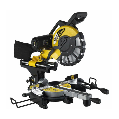
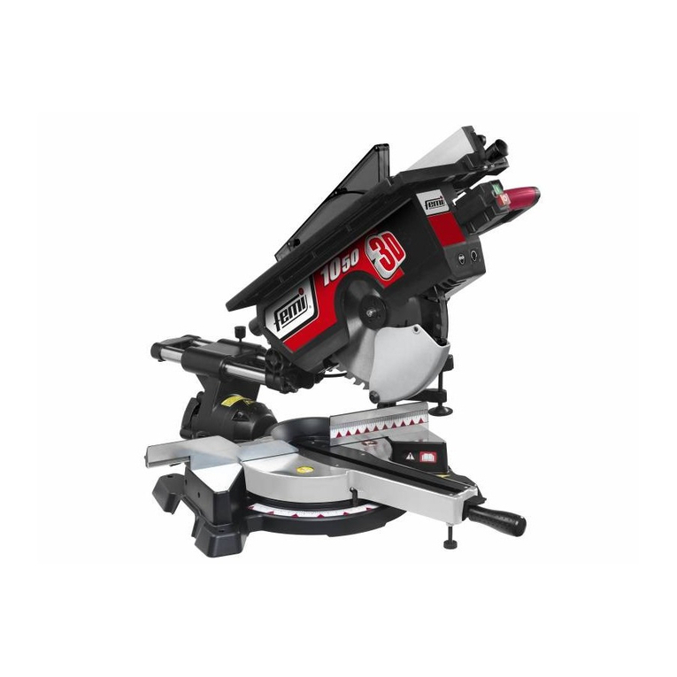
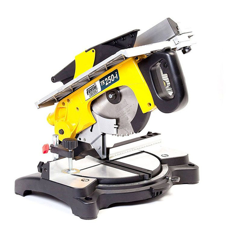
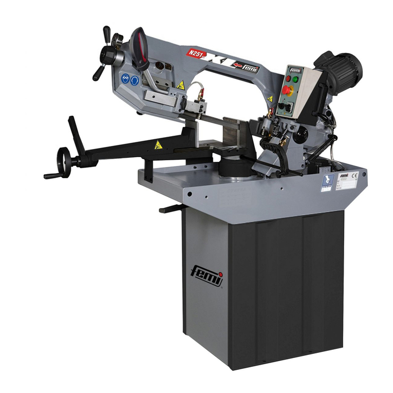
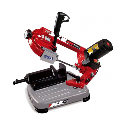
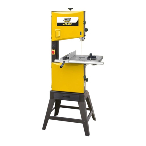
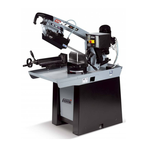
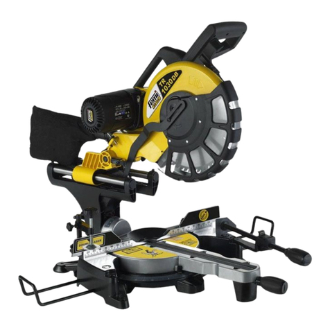
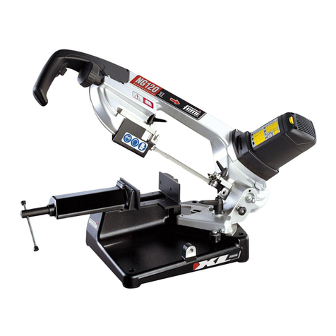
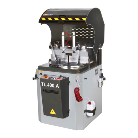
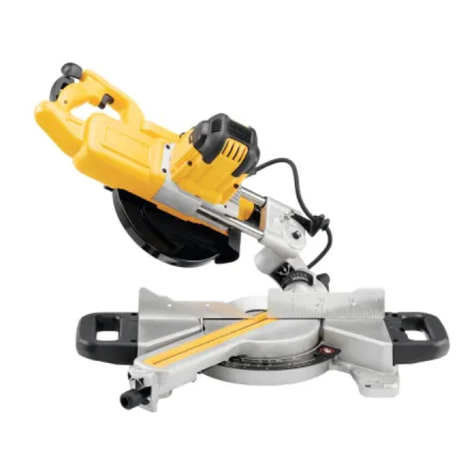
Femi 842 Specification sheet

ZZZIHPLLW
7521&$75,&(&,5&2/$5(
0,75(6$:6
.5(,66b*(1
6&,(6$21*/(7
7521=$'25$6
6(5527(&,5&8/$5
&(57,),&$7$
&(57,),('
*(35h)7
&(57,),(
&(57,),&$'$
&(57,),&$'$
$UW $UW $UW$/8
ISTRUZIONI PER L’USO E MANUTENZIONE
INSTRUCTIONS FOR USE AND MAINTENANCE
GEBRAUCHSANLEITUNGEN UND WARTUNG
MODE D’EMPLOI ET ENTRETIEN
INSTRUCCIONES PARA EL USO Y MANUTENCION
INSTRUÇÕES DE UTILIZAÇÃO

',&+,$5$=,21(',&21)250,7È&(
'(/&267587725()(0,6S$
Via Salieri, 35 - 40024 Castel San Pietro Terme (BO) - ITALIA
Tel. +39-051-941866 - Fax +39-051-6951332 - http://www.femi.it
Dichiara sotto la nostra esclusiva responsabilità che questa
macchina è conforme alle disposizioni della Direttiva Macchine
&(
ed è identico, in quanto incluso nell’ allegato IV della
direttiva, al macchinario oggetto della certificazione CE di tipo
(vedi etichetta riportata) rilasciata da ICE Istituto Certificazione
Europea SpA, organismo notificato n. 0303. E’ inoltre conforme
alle disposizioni delle seguenti altre direttive:
&(
&(
&20 /,$1&('(&/$5$7,21&(2)7+(%8,/'(5
)(0,6S$
Via Salieri, 35 - 40024 Castel San Pietro Terme (BO) - ITALIA
Tel. +39-051-941866 - Fax +39-051-6951332 - http://www.femi.it
Declare under our sole responsibility that the machine,to which
this declaration relates, is in conformity with the regulations
indicated in Machinery Directive
&(
and is identical, in that
it is included in appendix IV of the directive, to the machinery
concerning CE certification type (see relative label) issued by the
ICE (Istituto Certificazione Europea SpA), Notified Body no. 0303.
Furthermore it is also in conformity with the following standards:
&(&(
&(.21)250,7$76(5./$581*'(6+(567(//(5
)(0,6S$
Via Salieri, 35 - 40024 Castel San Pietro Terme (BO) - ITALIA
Tel. +39-051-941866 - Fax +39-051-6951332 - http://www.femi.it
Erklärt unter seiner alleinigen Verantwortung, dass diese
Maschine den Bestimmungen der Maschinenrichtlinie
(:*
entspricht, und, insofern eingeschlossen in Anhang IV der
Richtlinie, identisch mit der maschinellen Ausrüstung ist, die
Gegenstand der EG-Baumusterbescheinigung ist (siehe das
abgebildete Etikett), die vom ICE (Istituto Certificazione Europea
SpA, anerkannte Prüfstelle Nr. 0303) erlassen wurde. Sie
entspricht ferner den Bestimmungen der folgenden weiteren
Richtlinien:
&((:*
'(&/$5$7,21'(&21)250,7(&('8&216758&7(85
)(0,6S$
Via Salieri, 35 - 40024 Castel San Pietro Terme (BO) - ITALIA
Tel. +39-051-941866 - Fax +39-051-6951332 - http://www.femi.it
Déclare, sous sa propre responsabilité, que cette machine est
conforme aux dispositions de la Directive Machines
&(
et
est identique, car incluse dans l’annexe IV de la directive, à la
machine objet de la certification CE de type (voir étiquette
rapportée) remise par ICE Istituto Certificazione Europea SpA,
organisme notifié n° 0303. En outre, elle est conforme aux
dispositions des autres directives suivantes :
&(
&(
'(&/$5$7,21'(&21)250,'$'&('(/&216758&725
)(0,6S$
Via Salieri, 35 - 40024 Castel San Pietro Terme (BO) - ITALIA
Tel. +39-051-941866 - Fax +39-051-6951332 - http://www.femi.it
Declara bajo su exclusiva responsabilidad que esta máquina
cumple con lo dispuesto por la Directiva Máquinas
&(
y es
idéntica, en cuanto máquina que figura en el anexo IV de la
directiva, a la máquina objeto de la certificación CE de tipo
(véase etiqueta ilustrada) otorgada por ICE Instituto de
Certificación Europea SpA, organismo notificado nº 0303.
Asimismo, cumple también con lo dispuesto por las siguientes
directivas:
&(\&(
'(&/$5$d2'(&21)250,'$'(&('2
&2167587725(
)(0,6S$
Via Salieri, 35 - 40024 Castel San Pietro Terme (BO) -ITALIA
Tel. +39-051-941866 - Fax +39-051-6951332 - http://www.femi.it
Declaramos sob a nossa exclusiva responsabilidade que esta
máquina está em conformidade com as disposições da Directiva
Máquinas
&(
e que é idêntica, porque contemplada no
anexo IV da directiva, ao maquinário objecto da certificação CE
de tipo (ver a etiqueta indicada) emitida por ICE Istituto
Certificazione Europea SpA, organismo notificado nº 0303. Está
também em conformidade com as disposições das seguintes
directivas:
&(&(
23.07.2007

ZZZIHPLLW
,7$/,$12,7 ·
(1*/,6 (1 ·
'(876& '(·
)5$1&$,6)5·
(63$12/(6 ·
32578*8Ç637·
6&+(0$(/(775,&2:,5,1*',$*5$0(/(.75,6&+(56&+$/73/$16&+(0(
(/(&75,48((648(0$(/(&75,&2(648(0$(/e&75,&2
,7$/,$12 (1*/,6+ '(876&+
0
Motore Motor Motor
&
Condensatore Condensator Kondensator
30
Pulsante di marcia
Start switch Handschalter
)5$1&$,6 (63$12/ 32578*8 6
0
Moterur Motor Motor
&
Condensateur Condensator Condensador
30
Bouton marche Pulsador de marcia Botão de arranque

1
,7
,1',&(
1INTRODUZIONE ALL’USO............................ 1
2INSTALLAZIONE ........................................... 3
3REGOLAZIONI............................................... 4
4UTILIZZAZIONE - AVVERTENZE DI
SICUREZZA................................................... 4
5ACCESSORI.................................................. 6
6MANUTENZIONE .......................................... 6
7GUIDA ALLA LOCALIZZAZIONE DEI GUASTI
....................................................................... 8
,1752'8=,21($//862
Prima di iniziare le lavorazioni con la Vostra troncatrice,
leggete attentamente questo manuale di istruzioni, allo
scopo di conoscere la macchina ed i suoi impieghi, e le
eventuali controindicazioni.
Conservate con cura questo manuale: esso fa parte
integrante della macchina, e ad esso dovrete sempre
riferirvi per eseguire al meglio e nelle massime
condizioni di sicurezza le operazioni che in esso sono
descritte.
Il manuale và tenuto sempre insieme alla macchina, a
portata di mano per potere essere consultato ogni volta
si renda necessario.
Utilizzate la macchina solo ed esclusivamente per gli
impieghi di seguito specificati, usandola come
raccomandato in questo manuale, e non cercando in
alcun modo di manometterla o forzarla, o di usarla per
scopi non adatti.
6,0%2/2*,$87,/,==$7$1(/0$18$/(
Non sottovalutate i richiami "ATTENZIONE" e
"CAUTELA" riportati in questo manuale.
Al fine di attirare l’attenzione e dare messaggi di
sicurezza le operazioni pericolose sono precedute da
simboli e note che ne evidenziano la pericolosità e
spiegano come comportarsi per evitare il pericolo.
Questi simboli e note sono di tre categorie identificati
nelle parole:
$77(1=,21(
comportamenti rischiosi che
potrebbero provocare gravi lesioni.
&$87(/$
comportamenti che potrebbero
causare lesioni non gravi o danni alle cose.
127(
le note precedute da questo simbolo
sono di carattere tecnico e facilitano le
operazioni.
',0(16,21,',,1*20%52
9(56,21(
Lunghezza 580 mm-Larghezza 500 mm-Altezza 370 mm
Piano superiore ..................................................430 x 305 mm
*
* Dimensioni piano di lavoro ............................... 410 x 305 mm
Sporgenza massima lama piano superiore ...................40 mm
Massa .................................................................................. kg 1
9
9(56,21(
Lunghezza 580 mm-Larghezza 500 mm-Altezza 430 mm
Piano superiore ..................................................476 x 325 mm
*
* Dimensioni piano di lavoro ............................... 476 x 305 mm
Sporgenza massima lama piano superiore ..................50 mm.
Massa .................................................................................. kg 21
6,&85(==$(1250$7,9$
La macchina è progettata e costruita secondo le prescrizioni
imposte dalle vigenti Direttive Comunitarie:
&(
&(&(
.
La dichiarazione di conformità CE allegata, unita al marchio
CE posto sul prodotto, costituisce elemento fondamentale e
parte integrante della macchina: garantiscono la conformità
del prodotto alle Direttive di sicurezza sopra citate.
7, 2',,0 ,(*2(&21752,1',&$=,21,
La troncatrice circolare è stata progettata e realizzata con
l'impiego delle più avanzate tecnologie, ed è in grado di
soddisfare tutte le esigenze di taglio
di legno, alluminio e
materie plastiche tipiche del professionista, dell’artigiano e
dell’hobbista ai massimi livelli.
862&216(17,72
Essa puó tagliare:
- LEGNO DURO E TENERO, NAZIONALE ED
ESOTICO, LUNGO E TRAVERSO VENA.
e con adeguati adattamenti (lama specifica e morsetti):
-
MATERIE PLASTICHE
-
ALLUMINIO E SUE LEGHE
862121&216(17,72
Non è adatta per il taglio di:
-
MATERIALI FERROSI, ACCIAI E GHISE E DI
QUALSIASI ALTRO MATERIALE DIVERSO DA QUELLI
SPECIFICATI NELL’USO CONSENTITO, ED IN
PARTICOLARE DI SOSTANZE ALIMENTARI.
-
E’ ASSOLUTAMENTE VIETATO UTILIZZARE LA SEGA
CIRCOLARE SENZA PROTEZIONE LAMA.
1250(',6,&85(==$*(1(5$/,
–
Mantenete sempre pulita la zona di lavoro dai residui di
lavorazione.
–
Non usate la macchina in luoghi molto umidi o con
presenza di liquidi infiammabili o di gas.
–
Non usatela all'aperto, quando le condizioni generali meteo
ed ambiente non lo consentono (es. atmosfere esplosive,
durante un temporale o precipitazioni).
–
Vestitevi adeguatamente: evitate di indossare abiti con
maniche larghe od oggetti, come sciarpe, catene o
bracciali, che potrebbero essere agganciati dalle parti in
movimento.

2
,7
-
Usate sempre i dispositivi personali di protezione:
occhiali antinfortunistici conformi alle norme, guanti
di dimensioni adatte a quelle della mano, cuffie o
inserti auricolari e cuffie per il contenimento dei capelli, se
necessario.
-
Fate attenzione al cavo di alimentazione: non usatelo
per sollevare la macchina o per staccare la spina
dalla presa, e salvaguardatelo da spigoli vivi, oli e
zone con elevate temperature.
-
Tenete lontano i bambini dall’utensile: non lasciate
che si avvicinino e che vengano a contatto con esso.
-
Quando si rende necessario usare prolungamenti del
cavo di alimentazione, usate solo quelli di tipo
omologato.
-
Salvaguardatevi dall’elettrificazione: evitate contatti
con oggetti con messa a terra, come tubi, termosifoni
e frigoriferi.
-
Controllate sempre quello che state facendo.
-
Non utilizzate la macchina se siete stanchi.
-
Mantenete sempre posizione ed equilibrio ottimali.
-
Non lasciate sull’utensile chiavi o strumenti di misura.
-
Utilizzate maschere antipolvere adeguate.
5(&$8=,21, ', 6,&85(==$ (5
/¶87,/,==2
-
Non forzate inutilmente la macchina: una pressione
di taglio eccessiva può provocare un rapido
deterioramento della lama ed un peggioramento
delle prestazioni della macchina in termini di finitura
e di precisione di taglio.
-
Nel taglio dell'alluminio e delle materie plastiche si
consiglia di utilizzare gli appositi morsetti: i pezzi
oggetto di taglio devono sempre essere tenuti
fermamente nella morsa.
-
Evitate partenze accidentali: non tenete premuto il
pulsante di marcia mentre inserite la spina nella
presa di corrente.
-
Usate gli utensili raccomandati in questo manuale, se
volete ottenere dalla vostra troncatrice le migliori
prestazioni.
-
Tenete sempre le mani lontane dalle zone di
lavorazione mentre la macchina è in movimento;
prima di eseguire qualsiasi operazione rilasciate il
pulsante nell'impugnatura, spegnendo la macchina e
facendola fermare.
(5,&2/,(5,6&+,5(6,'8,
5LVFKLRUHVLGXRGLHVSRVL]LRQHDOUXPRUH
2ULJLQHGHOULVFKLRUHVLGXR
Sulle troncatrici permangono rischi residui legati alle
emissione acustiche prodotte dalle stesse durante la
lavorazione, in particolare, ad esempio, durante il
processo di taglio di una tavola in legno (abete) mm
90x30 traverso vena, o di un profilato di alluminio mm
40x40 spessore 2 mm, con i valori sopra citati.
UHFDX]LRQLDGRWWDWH
A bordo delle troncatrici sono apposte le etichette di
segnalazione, indicanti tale rischio e la necessità da
parte degli operatori / manutentori di indossare gli
appositi dispositivi di protezione acustica.
1RUPHGLVLFXUH]]D
$77(1=,21( /¶RSHUDWRUH HR L PDQXWHQWRUL
DXWRUL]]DWL SULPD G
L HIIHWWXDUH OH ODYRUD]LRQL
GHYRQR LQGRVVDUH JOL DSSRVLWL GLVSRVLWLYL GL
SURWH]LRQHGHOO¶DSSDUDWRXGLWLYR
,1)250$=,21, 5(/$7,9( $/ 58025( (
9,%5$=,21,
5XPRUH
Livello sonoro postazione
operatore (a vuoto) ................................. Leq = 74 dB(A)
Livello sonoro postazione operatore
(a carico) ..................................................Leq 81.2 db(A)
&RQGL]LRQLGHOOHSURYHDFDULFR
7DJOLR WDYROD LQ DEHWH [ DOOD YHORFLWj GL
JLULPLQ
Potenza Sonora (a vuoto) ....................... Lwa 85,7 db(A)
Potenza Sonora (a carico) ...................... Lwa 94,6 db(A)
7DJOLR SURILODWR GL DOOXPLQLR PP [ VSHVVRUH
PPDOODYHORFLWjGLJLULPLQ
Potenza Sonora (a vuoto) ....................... Lwa 83,6 db(A)
Potenza Sonora (a carico) .................... Lwa 101,4 db(A)
Le rilevazioni sono state eseguite utilizzando la norma
UNI EN ISO 3746
9LEUD]LRQL
Il valore medio quadratico ponderato in frequenza, dell’
accelerazione mano braccio, non supera i 2,5 m/sec2.
Le rilevazioni sono state eseguite utilizzando la norma
UNI EN ISO 5349-1 e 5349-2.
127( HU LO WDJOLR GHOO¶DOOXPLQLR q
LQGLVSHQVDELOH O¶XVR GHL
PH]]L SHUVRQDOL GL
SURWH]LRQH GHOO¶XGLWR FRPH FXIILH R LQVHUWL
DXULFRODUL/¶XVR GL WDOL PH]]L q FRQVLJOLDWRSHU
WXWWLJOLDOWULLPSLHJKL
,1)250$=,21, 68//$ &20 $7,%,/,7$
(/(77520$*1(7,&$
Le recenti Normative Europee sulla sicurezza, ed in
particolare la Direttiva 2004/108/CE, prescrivono che
tutte le apparecchiature siano dotate di dispositivi di
schermatura per i radiodisturbi sia da che verso
l’ambiente esterno. Questa macchina è conforme alle
prescrizioni. Le prove sono s
tate eseguite secondo le
Norme EN 55014-1, EN 55014-2.
'(6&5,=,21('(//$0$&&+,1$)LJ
La troncatrice circolare è composta da tre parti
fondamentali: il corpo cen
trale , comprendente il motore
, che è collegato alla base
tramite lo snodo
ed il
supporto girevole
, ed il gruppo di lavoro superiore,
comprendente il piano di lavoro
, la squadra di
appoggio
e la protezione mobile della lama
.

3
,7
La base
viene impiegata come appoggio quando si
devono eseguire operazioni di troncatura ed intestatura
nelle diverse angolazioni disponibili; il piano superiore
viene impiegato come appoggio quando si devono
rifilare o sezionare tavole di legno di grandi dimensioni,
ed in particolare nel taglio del legno lungo vena.
/HJHQGD)LJ
Impugnatura di comando
Interruttore di marcia
Base
Snodo corpo/base
Supporto girevole
Motore
Lama
Leva sblocco graduazione
Pulsante di sblocco discesa corpo
Protezione fissa lama
Protezione mobile lama
Aste fermo barra (optional)
Collettore scarico polvere
Morsetti ferma pezzo (optional)
Piano di lavoro superiore
Protezione mobile superiore
Squadra di appoggio
Piedi di appoggio
Perno di blocco
Pulsante blocco interruttore
Pulsante rilascio interruttore
,167$//$=,21(
5,02=,21('(//,0%$//2
Rimuovete la scatola che protegge la macchina durante
il trasporto, avendo cura di mantenerla intatta, nel caso
dobbiate spostare la troncatrice per lunghi tragitti o
immagazzinarla per lunghi periodi.
029,0(17$=,21(
Date le dimensioni ridotte ed il peso contenuto, la
troncatrice può essere comodamente movimentata
anche da una sola persona, azionando l’apposito
blocco per il trasporto tramite lo spinotto 19 e
sollevando la macchina dall’impugnatura di comando 1.
$77(1=,21( 'XUDQWH LO WUDVSRUWR OD SDUWH
VXSHULRUH GHOOD ODPD GHOOD WURQFDWULFH GHYH
HVVHUHFRSHUWD9HULILFDUH VHPSUH FKH ODPD
VLD SURWHWWD GDOOD DSSRVLWD SURWH]LRQH
VXSHULRUH
75$6 2572
Nel caso si renda necessario trasportare la macchina,
rimettetela nella scatola originale nella quale era
contenuta al momento dell’acquisto, facendo attenzione
ad inserirla nella giusta posizione rispetto alle frecce
presenti sull’imba
llo. Prestate molta attenzione agli
ideogrammi stampati sulla scatola, che forniscono le
indicazioni di pallettizzazione e sovrapposizione di più
scatole. Per quanto possibile, è buona norma fissare il
carico con corde o cinghie di sicurezza, per evitare
spostamenti e cadute del carico durante il trasporto.
26,=,21$0(172 2672',/$9252)LJ
Posizionate la macchina su un banco oppure su un
basamento/piedistallo sufficientemente piano, in modo
da avere la migliore stabilità possibile. Per un eventuale
fissaggio utilizzare gli appositi fori previsti sulla base.
Per eseguire le lavorazioni tenendo conto dei criteri
ergonomici, l’altezza ideale del banco o del basamento
deve essere quella che vi c
onsente di posizionare il
piano della base, oppure il piano di lavoro superiore, tra i
90 ed i 95 cm. da terra
YHGL)LJ
.
Il posizionamento della macchina sul posto di lavoro
deve essere eseguito in modo da avere almeno 80 cm di
spazio circostante, in
tutte le direzioni, intorno alla
macchina, per potere effettuare con assoluta sicurezza e
spazio di manovra sufficiente la pulizia, la manutenzione
e le regolazioni necessarie
YHGL)LJ
.
&$87(/$
$EELDWH FXUD GL SRVL]LRQDUH OD
PDFFKLQDLQXQD ]R
QDGLODYRUR DGHJXDWDVLD
FRPH FRQGL]LRQL DPELHQWDOL FKH FRPH
OXPLQRVLWjULFRUGDWHVHPSUHFKHOHFRQGL]LRQL
JHQHUDOL GHOODPELHQWH GL ODYRUR VRQR
IRQGDPHQWDOLQHOODSUHYHQ]LRQHGHJOLLQIRUWXQL
&2//(*$0(172(/(775,&2
Controllate che l’impianto rete sul quale inserite la
macchina sia collegato a terra come previsto dalle
norme di sicurezza vigenti, e che la presa di corrente sia
in buono stato. Si ricorda all’utilizzatore che a monte
dell’impianto rete deve essere presente una protezione
magnetotermica atta a salvaguardare tutti i conduttori dai
corto circuiti e dai sovraccarichi. Tale protezione dovrà
essere scelta anche in base alle caratteristiche elettriche
della macchina riportate sul motore.
127( /LPSLDQWR HOHW
WULFR GHOOD YRVWUD
WURQFDWULFHqGRWDWRGLUHOqGLPLQLPDWHQVLRQH
FKHDSUHDXWRPDWLFDPHQWHLOFLUFXLWRTXDQGROD
WHQVLRQH VFHQGH VRWWR XQ OLPLWH PLQLPR
VWDELOLWR H FKH LPSHGLVFH LO ULSULVWLQR
DXWRPDWLFR GHOOD FRQGL]LRQH GL IXQ]LRQDPHQWR
TXDQGR OD WHQVLR
QH ULWRUQD DL OLYHOOL QRPLQDOL
SUHYLVWL6H OD PDFFKLQD VXELVFH XQ DUUHVWR
LQYRORQWDULRQRQDOODUPDWHYLPDFRQWUROODWHVH
HIIHWWLYDPHQWHVLDYHQXWDDPDQFDUHODWHQVLRQH
QHOOLPSLDQWRGLUHWH

4
,7
5(*2/$=,21,
$77(1=,21( 7XWWH OH RSHUD]LRQL GL
UHJROD]LRQH LOOXVWUDWH QHL SDUDJUDIL VHJXHQWL
GHYRQR HVVHUH HIIHWWXDWH FRQ PRWRUH GHOOD
PDFFKLQDVSHQWR
5(*2/$=,21( '(//$1*2/2 ', 7$*/,2
527$=,21(7(67$)LJ
La troncatrice è in grado di effettuare tagli orientati sia
verso destra che verso sinistra.
Le posizioni fisse già tarate sono: 15°, 22° 30', 30° e
45°.
Per ottenere queste posizioni, allentare la manopola
,
sbloccate la testa della macchina, spingendo verso il
basso la leva
, e fate ruotare il supporto girevole
tramite l'impugnatura
.
La testa si arresterà automaticamente quando di volta
in volta l'indice
si troverà allineato alla
corrispondente posizione scelta sulla targa graduata del
girevole.
Per tutte le posizioni intermedie, una volta allineato
l'indice con la posizione sulla targa, bloccate il supporto
girevole tramite la manopola
.
5(*2/$=,21( '(//$1*2/2 ', 7$*/,2
,1&/,1$=,21(7(67$)LJ
La testa della macchina può inclinarsi fino ad un
massimo di 45° verso sinistra.
Sbloccate la manopola
nella parte posteriore della
macchina, ed inclinate la testa fino all'arresto sul fermo
a 45° già tarato al momento del collaudo, bloccare
quindi di nuovo la testa mediante la manopola
.
Per tutte le altre posizioni intermedie, fate coincidere
l'indice
posto sulla parte posteriore della testa con la
corrispondente posizione impressa sulla scala graduata
dello snodo.
$77(1=,21(1HOWDJOLRDGRSSLDLQFOLQD]LRQH
URWD]LRQH SL LQFOLQD]LRQH WHVWD WHQHUH LO
SH]]RVDOGRDOODPDFFKLQDFRQODPDQRGHVWUD
H JXLGDUH OD GLVFHVD GHOOD WHVWD FRQ OD PDQR
VLQLVWUD)LJ
5(*2/$=,21(0217$**,2 '(/ )(502
%$55$2 7,21$/)LJ
Se dovete effettuare più tagli di pezzi tutti della stessa
lunghezza, usate l'arresto barra, evitando così di rifare
tutte le volte la stessa misura.
Avvitate l'asta
nel foro della base e bloccatela con il
grano
; allentate il volantino
e posizionate il fermo
alla distanza necessaria dalla lama; ribloccate il
volantino
.
5(*2/$=,21($/7(==$ ,$1268 (5,25(
)LJ
62/2 (56(*$&,5&2/$5(
$77(1=,21(/DYRUDQGRVXOSLDQRVXSHULRUHq
QHFHVVDULR PRQWDUH LO FDUWHU GL SURWH]LRQH
LQIHULRUHLQGRWD]LRQH)LJ
Per montare il carter, con la testa sollevata, inseritelo
negli appositi fori sulle protezioni fisse, dopo di che
abbassate di nuovo la testa e bloccate il corpo in questa
posizione tramite il perno di bloccaggio 19. Per regolare
l'altezza del piano superiore, in modo da effettuare il
taglio dello spessore desiderato, eseguite le seguenti
operazioni:
–allentate i due volantini 32;
–avvicinate la squadra di appoggio 17 alla lama;
–abbassate o alzate il piano, fino all'altezza di taglio
desiderata;
–bloccate i due volantini 32.
5(*2/$=,21( '(//$ 648$'5$ ',
$ 2**,2)LJ
62/2 (56(*$&,5&2/$5(
Potete avvicinare o allontanare la squadra di appoggio
dalla lama, in modo da eseguire il taglio di tavole di
misura prestabilita.
Allentate ilvolantino
, e fate scorrere la squadra
,
facendo coincidere l'indice
sul supporto con la
rispettiva posizione sulla scala graduata ricavata nel
piano di lavoro, posizione che corrisponde alla effettiva
distanza dell'appoggio della squadra con la mezzeria
della lama.
5(*2/$=,21(&81(2
Perchè il cuneo divisore sia nella posizione corretta,
tenerlo ad una distanza tra i 3 mm e gli 8 mm dal dente
della lama. Nel caso non fosse così, agire sulla vite di
fissaggio al braccio e portarlo alla distanza descritta in
precedenza
)LJ
.
87,/,==$=,21( $99(57(1=( ',
6,&85(==$
Una volta eseguite tutte le procedure e le operazioni fin
qui descritte, potete iniziare le lavorazioni, facendo
riferimento alle seguenti prescrizioni di sicurezza.

5
,7
$77(1=,21(
7HQHWHVHPSUHOHPDQLORQWDQHGDOOD]RQD
GL WDJOLR H QRQ FHUFDWH LQ DOFXQ PRGR GL
UDJJLXQJHUODGXUDQWHOHRSHUD]LRQL
Ê
DVVROXWDPHQWH YLHWDWR XWLOL]]DUH OD
PDFFKLQDSHUHIIHWWXDUHWDJOLFLHFKL
9HULILFDUH VHPSUH SULPD GL RJQL
ODYRUD]LRQH FKH SRPHOOL H OHYH GL
EORFFDJJLRVLDQRFRUUHWWDPHQWHVHUUDWL
Ê
DVVROXWDPHQWH YLHWDWR XWLOL]]DUH OD
PDFFKLQD QHO FDVR O¶LQWHUUXWWRUH QRQ
DFFHQGDQqVSHQJDODPDFFKLQDVWHVVD
9HULILFDUH VHPSUH SULPD GL D]LRQDUH OH
PDFFKLQD FKH WXWWH OH SURWH]LRQL VLDQR
FRUUHWWDPHQWH PRQWDWH H FKH SURWHJJDQR
DGHJXDWDPHQWHODODPD
862&20(7521&$75,&(WDJOLRVXOSLDQR
LQIHULRUH)LJ
–
Sbloccate la testa, svitando il perno di blocco
.
–
Sollevate la testa della macchina fino alla massima
escursione.
–
Assicurate saldamente il pezzo da tagliare contro gli
appoggi angolari
della base, con la mano sinistra,
in modo che non possa muoversi durante il taglio.
–
Ponete la mano destra sull’impugnatura
, e premete
il pulsante
in modo da sbloccare il movimento della
testa.
–
Azionate il motore, premendo prima il pulsante di
rilascio
, poi il pulsante di marcia
sull’impugnatura.
–
Fate scendere la testa, e mettete gradualmente a
contatto la lama con il pezzo da tagliare.
–
Eseguite il taglio completo del pezzo, e riportate la
testa nella posizione originale.
–
Spegnete il motore, rilasciando il pulsante
.
862 &20( 6(*$ &,5&2/$5( WDJOLR VXO
SLDQRVXSHULRUH)LJ
$77(1=,21(9HULILFDUHVHPSUHSULPDGLRJQL
ODYRUD]LRQH VXO SLDQR FKH OD WHVWD GHOOD
PDFFKLQD VLD FRUUHWWDPHQWH EORFFDWD LQ
SRVL]LRQHDEEDVVDWD
$77(1=,21(/DYRUDQGRVXOSLDQRVXSHULRUH
q QHFHVVDULR PRQWDUH LO FDUWHU GL SURWH]LRQH
LQIHULRUHLQGRWD]LRQH
$77(1=,21( /D PDFFKLQD q GRWDWD GL
VSLQWRUH GL GLPHQVLRQL H IRUPD FRQIRUPL D
TXHOOHSUHVFULWWHGDOOHQRUPHGLVLFXUH]]D)LJ
4XDQGRODPDFFKLQDYLHQHXVDWDFRPH6(*$
&,5&2/$5( XWLOL]]DQGR SHU OH ODYRUD]LRQL LO
SLDQR GL ODYRUR VXSHULRUH WDOH DFFHVVRULR
GHYHHVVHUH2%%/,*$725,$0(17(XWLOL]]DWR
/R VSLQWRUH YD LPSXJQDWR QHOOD SDUWH $
PHQWUHODSDUWH%GRWDWDGLGLYHUVLJUDGLQLSHU
O¶DGDWWDPHQWR D VSHVVRUL GLIIHUHQWL GHYH
HVVHUH SRVWD D FRQWDWWR FRQ LO SH]]R GD
WDJOLDUH FRPH PRVWUDWR LQ ILJXUD 7UDPLWH OR
VSLQWRUH q SRVVLELOH VSLQJHUH LO SH]]R GD
WDJOLDUH JXLGDQGROR FRQWHPSRUDQHDPHQWH
WUDPLWH O¶DSSRJJLR VXOOD VTXDGUD & H
PDQWHQHQGR VHPSUH OH PDQL GLVWDQWL GDOOD
]RQDGLWDJOLRGHOODODPD
–
Con motore spento, bloccate la testa della macchina
in posizione abbassata, tramite il perno di blocco 19.
–
Regolate l'altezza del piano superiore in base
all'altezza di taglio voluta e la squadra di appoggio
come descritto al paragrafo “REGOLAZIONI”.
–
Controllate il corretto funzionamento della protezione
mobile superiore: dopo averla alzata leggermente,
deve ritornare nella posizione originale, coprendo
completamente la lama.
–
Azionate il motore come descritto al punto 4.1, e
bloccate l’interruttore nella posizione di chiuso,
premendo il pulsante di blocco 51 situato nella zona
inferiore dell’impugnatura.
–
Posizionate la tavola da sezionare sul piano,
appoggiandola lateralmente sulla squadra, e fate
avanzare il pezzo da tagliare in modo regolare e
senza forzature verso la lama.
&$87(/$
,O SH]]R GD WDJOLDUH GHYH VHPSUH
HVVHUHWHQXWRVDOGDPHQWHDYHQGRODFFRUWH]]D
GLLPSXJQDUORORQWDQRGDOODOLQHDGLWDJOLRGHOOD
ODPD
–
Per fermare la macchina, premete l’interruttore di
marcia
, che sblocca automaticamente il pulsante di
blocco
.
0217$**,2 (2 6267,78=,21( '(//$
/$0$)LJ
$77(1=,21( (IIHWWXDWH TXHVWH RSHUD]LRQL
VRODPHQWH GRSR DYHUH IHUPDWR LO PRWRUH GHOOD
PDFFKLQD ULODVFLDQGR LO SXOVDQWH GL PDUFLD
GHOO¶LQWHUUXWWRUH
H GRSR DYHU VH]LRQDWR
O¶DOLPHQWD]LRQH
–
Sbloccate la protezione mobile
, premendo il
nottolino
e contemporaneamente sollevando la
protezione, in modo da scoprire la lama.
–
Sollevate il piano superiore fino alla sua massima
altezza.
–
Prendete le due chiavi esagonali da 6 mm in
dotazione: inseritene una nel terminale 41 dell’albero
motore, l’altra nella vite di fissaggio della lama 42; a
questo punto svitate la vite,
tenendo presente che la
filettatura della vite è sinistrorsa.

6
,7
–
T
ogliete la flangia esterna 43, smontate
la
l
ama sfilandola dalla parte inferiore del
la
testa, e montate la lama nuova.
–
A
ssicuratevi, mediante controllo a vista,
di
mo
n
tare la lama con la dentatura orientat
a
n
ella direzione evidenziata dalla freccia post
a
sulla stessa.
–
A
questo punto, rimontate la flangia estern
a
4
3, riavvitate la vite 42 e serratela con forz
a
mediante le chiavi esagonali in dotazione.
–
Abbassate il piano.
127( /D SURWH]LRQH PRELOH ULWRUQHUj
QHOODFRUUHWWDSRVL]LRQHDXWRPDWLFDPHQWHDOOD
SULPD GLVFHVD GHOOD WHVWD GHOOD PDFFKLQD
VHQ]DELVRJQRGLULSRVL]LRQDUHLOQRWWROLQR
$77(1=,21(
o
È assolutamente vietato montare lame che alla
vista risult
ino incrinate. Montare esclusivamente
lame a norma EN 847-1.
o
È assolutamente vietato utilizzare lame ad alta
velocità in acciaio.
o
Utilizzate sempre lame affilate e di dimensioni
idonee.
&$ $&,7$',7$*/,2)LJ
Le tabelle di seguito riportate specificano le capacità
di taglio a 0° e 45° ottenibili nelle normali condizioni di
utilizzo descritte in questo manuale.
9(56,21(
9(56,21(
$&&(6625,
6&(/7$'(//$/$0$
La troncatrice è dotata di serie di lama al WIDIA
(diametro 250 x foro 30, nella versione 250,
diametro 300 x foro 30 nella versione 300.
0256(77,)LJ2 7,21$/
&$87(/$4XD
QGRGRYHWHWDJOLDUHEDUUHRSH]]L
GL DOOXPLQLR R GL SODVWLFD VL FRQVLJOLD GL
XWLOL]]DUHLOPRUVHWWRSHUDVVLFXUDUHLOSH]]RDJOL
DSSRJJL DQJRODUL HYLWDQGR FRVu FKH VL PXRYD
GXUDQWH LO WDJOLR FDXVDQGR LQFHSSDPHQWL FKH
SRWUHEEHUR GDQQHJJLDUH LO SH]]R VWHVVR H OD
ODPD
Verificare sempre che il pressore del morsetto sia ben a
contatto con il pezzo da tagliare e che lo blocchi in modo
efficace sulla base.
$6 ,5$=,21( '(//( 2/9(5, )LJ
2 7,21$/
La troncatrice è predisposta per il collegamento con un
aspiratore, o per il montaggio del sacchetto raccogli
polvere, tramite il collettore di scarico
.
Il tubo dell’aspiratore o la manichetta del sacchetto
devono essere fissati al collettore tramite una fascetta.
Vi raccomandiamo di svuotare periodicamente il
sacchetto o il contenitore dell’aspiratore, e di pulire il
filtro.
La velocità di uscita dell’aria creata dall’aspiratore deve
essere almeno di 100 Nm3/h.
Aspiratori capaci di creare quest
e depressioni sono ad
esempio quelli di tipo “bidone”.
0$187(1=,21(
,17(59(17,',0$187(1=,21(25',1$5,$
Le normali operazioni di manutenzione ordinaria,
effettuabili anche da p
ersonale non specializzato, sono
tutte descritte nei paragrafi precedenti e nel presente.
1.
La troncatrice non ha bisogno di alcuna
lubrificazione, in quanto il taglio deve essere sempre
effettuato a secco (compreso quello dell'alluminio e
delle leghe le
ggere); tutti gli organi rotanti della
macchina sono autolubrificati.
2.
Durante le operazioni di manutenzione, indossate per
quanto possibile i mezzi personali di protezione
(occhiali antinfortunistici e guanti)
3.
Rimuovete i trucioli residui di lavorazione ogni
qualvolta si renda necessario, intervenendo nella
zona di taglio e sui piani di appoggio.
E' consigliato l'uso di un aspiratore o di un pennello.
$77(1=,21(
1RQ XVDWH JHWWL GL DULD
FRPSUHVVD
ULPD GL HVHJXLUH TXDOXQTXH RSHUD]LRQH GL
ULSDUD]LRQH R PDQXWHQ]LRQH VH]LRQDWH
O¶DOLPHQWD]LRQHHOHWWULFD
4.
Verificate periodicamente le condizioni della lama: se
doveste riscontrare difficoltà nel taglio, fatela affilare
da personale specializzato, oppure sostituitela, se
dovesse presentarsene la necessità.

7
,7
5
. Verificare periodicamente che l’ arresto della lama
avvenga entro 10 secondi dal rilascio del pulsante e
che la molla del braccio permetta al braccio di
risalire fino al fermo meccanico in un tempo non
superiore ai 2 secondi se questo non avviene fate
controllare la vostra troncatrice da personale
autorizzato.
$66,67(1=$
Nel caso sia necessario l’intervento di personale
specializzato per operazioni di manutenzione
straordinaria, oppure nel caso di riparazioni, sia in
regime di garanzia che successivamente, rivolgetevi
sempre ad un centro di assistenza autorizzato,
oppure direttamente alla fabbrica, se nella vostra zona
non e’ presente il centro di assistenza.
60$/7,0(1720$&&+,1$,0%$//$**,2
,1)250$=,21($*/,87(17,
Ai sensi dell’art. 13 del Decreto
Legislativo 25 luglio 2005, n. 151
“Attuazione delle Direttive
2002/95/CE, 2002/96/CE e
2003/108/CE, relative alla
riduzione dell’uso di sostanze
pericolose nelle apparecchiature elettriche ed
elettroniche, nonché allo smaltimento dei rifiuti”, si
precisa quanto segue:
•
Il simbolo del cassonetto barrato riportato
sull’apparecchiatura o sulla confezione indica che il
prodotto alla fine della propria vita utile deve essere
raccolto separatamente dagli altri rifiuti.
•
L’utente dovrà, pertanto conferire l’apparecchiatura
giunta a fine vita agli idonei centri di raccolta
differenziata dei rifiuti elett
ronici ed elettrotecnici,
oppure riconsegnarla al rivenditore al momento
dell’acquisto di una nuova apparecchiatura di tipo
equivalente, in ragione di uno a uno.
•
L’adeguata raccolta differenziata per l’avvio
successivo dell’apparecchiatura dismessa al
riciclaggio, al trattamento e allo smaltimento
ambientalmente compatibile contribuisce ad evitare
possibili effetti negativi sull’ambiente e sulla salute e
favorisce il reimpiego e/o riciclo dei materiali di cui è
composta l’apparecchiatura.
$77(1=,21(
/R VPDOWLPHQWR DEXVLYR GHO SURGRWWR GD SDUWH
GHOO¶XWHQWH FRPSRUWD O¶DSSOLFD]LRQH GHOOH
VDQ]LRQL DPPLQLVWUDWLYH SUHYLVWH GDOOD
QRUPDWLYDYLJHQWH

8
,7
*8,'$$//$/2&$/,==$=,21('(,*8$67,
52%/(0$ 52%$%,/(&$86$ 5,0(',268**(5,72
,OPRWRUHQRQIXQ]LRQD
1. Motore, cavo rete o spina
difettosi.
2. Fusibili bruciati.
1. Fate controllare la macchina da
personale specializzato.
Non cercate di riparare da soli il
motore: potrebbe essere
pericoloso.
2. Controllate i fusibili e sostituiteli
se necessario.
,OPRWRUHSDUWHOHQWDPHQWHRQRQ
UDJJLXQJHODYHORFLWjGL
IXQ]LRQDPHQWR
1. Bassa tensione di alimentazione.
2. Avvolgimenti danneggiati.
3. Condensatore bruciato.
1. Richiedete un controllo della
tensione disponibile da parte
dell’Ente erogatore.
2. Fate controllare il motore della
macchina da personale
specializzato.
3. Fate sostituire il condensatore da
personale specializzato.
(FFHVVLYRUXPRUHGHOPRWRUH
1. Avvolgimenti danneggiati.
Motore difettoso.
1. Fate controllare il motore da
personale specializzato.
,OPRWRUHQRQVYLOXSSDODSLHQD
SRWHQ]D
1. Circuiti dell’impianto rete
sovraccaricati da luci, servizi o
altri motori.
1. Non utilizzate servizi o altri
motori sullo stesso circuito al
quale collegate la macchina.
,OPRWRUHWHQGHDVXUULVFDOGDUH
1. Il motore è sovraccaricato.
2. Raffreddamento del motore non
adeguato.
1. Evitare di sovraccaricare il
motore durante l’operazione di
taglio.
2. Rimuovere la polvere dal motore
per ottenere il corretto flusso
dell’aria di refrigerazione.
5LGX]LRQHGHOODFDSDFLWjGLWDJOLR
1. La lama è stata affilata molte
volte e si è ridotta di diametro.
1. Intervenite sulla regolazione del
fine corsa della discesa della
testa.
/DILQLWXUDGHOWDJOLRULVXOWD
JUH]]DRRQGXODWD
1. La lama è consumata oppure
non ha la dentatura adatta allo
spessore del materiale che state
tagliando.
1. Fate affilare la lama da un centro
di affilatura specializzato.
2. Controllate se la dentatura che
state usando è giusta nel
paragrafo “SCELTA DELLA
LAMA”.
6FKHJJLDWXUDGHOSH]]RWDJOLDWR
1 La dentatura della lama non è
adatta al pezzo che state
tagliando.
1. Controllate qual è la giusta
dentatura da utilizzare nel
paragrafo “SCELTA DELLA
LAMA”.

9
(1
,1'(;
1 INTRODUCTION TO USE .............................9
2 INSTALLATION............................................11
3 ADJUSTING (Fig. 4-5-6-7-8)........................12
4 USE – SAFETY WARNINGS .......................12
5 ACCESSORIES............................................14
6 MAINTENANCE ...........................................14
7 TROUBLESHOOTING ...................................9
,1752'8&7,217286(
Before using your mitre-saw, please read this
instruction manual very carefully in order to become
familiar with the machine and its recommended use.
Do not lose this manual as it is an essential part of the
machine itself. We recommend you always refer to it in
order to operate the machine in the best and safest way
possible.
Keep the manual with the machine and handy at all
times so it can be consulted whenever necessary.
Use the machine exclusively for the uses specified
below, follow manual instructions carefully and never try
to force or to tamper with it, or to use it inappropriately.
6$)(7<,1)250$7,21$1'127(6
Do not underestimate the symbols "HAZARD" and
"CAUTION" in this manual.
Symbols and notes precede all hazardous operations
both to give safety indications, to draw the users'
attention to danger and also to outline the appropriate
behaviour to adopt to avoid such events.
The three symbols used and relative wording are the
following:
:$51,1*
a hazardous situation/action which
could be severely harmful.
&$87,21
a situation/action which could be
moderately harmful or damage objects.
127(
the notes preceded by this symbol are of
a technical nature and simplify use.
29(5$//',0(16,216
9
(56,21
Length 580 mm-Width 500 mm-Height 370 mm
Upper work surface 430 x 305 mm *
*Dimensions of work surface 410 x 305 mm
Upper work surface max protrusion of blade 40 mm
Weight 19kg
9
(56,21
Length 580 mm-Width 500 mm-Height 430 mm
Upper work surface 476 x 325 mm*
*Dimensions of work surface 476 x 305 mm
Upper work surface max protrusion of blade........50 mm.
Weight 21kg
6$)(7<$1'58/(6
The machine was designed and built according to the
Community Directives in force:
&(&(
&(
The enclosed CE Declaration of conformity, together
with the CE mark on the product itself are an integral
part of the machine: both guarantee product conformity
with the aforesaid safety Directives.
(19,6$*('86($1'81)25(6((186(
The most advanced technologies have been used to
design and manufacture the mitre-
saw. It is suitable to
cut wood, aluminium and plastics and can be used by
professionals, craftsmen and expert hobbyists alike.
(19,6$*('86(
To cut:
-
HARD AND SOFT, DOMESTIC AND EXOTIC WOOD
BOTH LONGITUDINALLY AND TRANSVERSALLY
and with appropriate adjustments (specific blade and
clamps):
-
PLASTICS
-
ALUMINIUM AND ALUMINIUM ALLOYS
81)25(6((186(
Do not cut:
-
FERROUS MATERIALS, STEEL AND CAST IRON OR
ANY OTHER MATERIAL NOT MENTIONED ABOVE
-
USE OF THE CIRCULAR SAW WITHOUT THE BLADE
GUARD IS STRICTLY PROHIBITED
67$1'$5'6$)(7<352&('85(
-
Remove all cuttings from the work surface ensuring it is
completely clean.
-
Use the machine in dry areas and away from
inflammable substances or gas.
-
Do not use the machine outdoors in adverse weather or
environmental conditions (explosive atmospheres,
storms or rain).
-
Wear appropriate clothing: do not wear loose-sleeved
garments or objects such as scarves, chains or bracelets
which may get caught in the machine's moving parts.

10
(1
-
Always use personal protective equipment: standard
accident-prevention goggles, well-fitting gloves,
earphones or earplugs and headgear to cover hair if
necessary.
-
Handle the power supply cable with care: do not use it
to lift the machine or to pull the plug out of the socket.
Keep it away from cutting edges, oily patches and
high temperatures.
-
Keep the machine out of the reach of children: do not
allow them to approach or touch the machine.
-
When in need, only use approved power supply
extension flexes.
-
Beware of electrocution: avoid all contact with earthed
objects such as pipes, radiators and refrigerators.
6$)(7< 35(&$87,216 72 %( $'237('
'85,1*86(
-
Do not force the machine unnecessarily: excessive
cutting pressure may lead to rapid deterioration of the
blade and a decrease in performance in terms of
finish and cutting precision.
-
When cutting aluminium or plastics, it is advisable to
use the clamps designed for this purpose: the pieces
to be cut must always be held firmly in the vice.
-
Avoid accidental start-up: do not press the start button
while inserting the plug into the socket.
-
Always use the tools recommended in this manual to
obtain the best results from your cutting machine.
-
Always keep hands away from the work area when
the machine is running; before performing tasks of
any kind release the main switch located on the
handgrip, thus disconnecting the machine.
+$=$5'6$1'5(6,'8$/5,6.6
5HVLGXDOULVNFDXVHGE\H[SRVXUHWRQRLVH
6RXUFHRIUHVLGXDOULVN
T
he mitre-saw is associated with residual risks
c
oncerning acoustic emissions generated by the saw
itself during operation, in particular (for example) when
c
utting a 90x30-mm plank of wood (deal) across the
g
rain, or when cutting a 40x40-mm aluminium section
bar which is 2 mm thick (see the aforementioned
v
alues).
3UHFDXWLRQVDGRSWHG
Warning stickers are affixed to the machine itself
indicating the risk and the need for all
operators/maintenance technicians to wear appropriate
hearing protection.
6DIHW\VWDQGDUGV
:$51,1* 7KH RSHUDWRU DQGRU DXWKRUL]HG
PDLQWHQDQFH WHFKQLFLDQV PXVW DOZD\V ZHDU
DSSURSULDWH KHDULQJ SURWHFWLRQ EHIRUH
ZRUNLQJZLWKRURQWKHPDFKLQH
,1)250$7,21 &21&(51,1* 12,6( $1'
9,%5$7,21/(9(/6
1RLVH
Noise level at the operator’s work position (without load)
.................................................................... Leq 74 db(A)
Noise level at the operator’s work position (with
load)………………..Leq 81.2 db(A)
7HVWFRQGLWLRQVZKHQZRUNLQJZLWKORDG
&XWWLQJ D GHDO SODQN [ PP DW WKH VSHHG RI
UHYPLQ
Sound power (without load) .....................Lwa 85.7 db(A)
Sound power (with load) ..........................Lwa 94.6 db(A)
&XWWLQJDQDOXPLQLXPVHFWLRQEDU [ PPPP
WKLFNDWWKHVSHHGRIUHYPLQ
Sound power (without load) .....................Lwa 83.6 db(A)
Sound power (with load) ........................Lwa 101.4 db(A)
T
he measurements were carried out in accordance with
standard
UNI EN ISO 3746
9
LEUDWLRQ
Mean frequenc
y
-weighted hand - arm acceleration
v
ibration exposure does not exceed 2.5 m/s².
T
he measurements were carried out in accordance with
standard
s
UNI EN ISO 5349-1 and 5349-2
127(:KHQ FXWWLQJ DOXPLQLXP WKH XVH RI
SURWHFWLYH HDUSKRQHV RU HDU SOXJV LV
DEVROXWHO\QHFHVVDU\
7KHXVHR
IWKLVJHDULVDOVRUHFRPPHQGHGIRU
DOORWKHUXVHV
,1)250$7,21 $%287
(/(&7520$*1(7,&&203$7,%,/,7<
The European regulations on safety and, in particular,
the 2004/108/EEC contemplate that all the equipment
be equipped with shielding devices against radio
interferences both from and towards the outside.
This machine is safe and in compliance with the above
regulations.
Tests were carried out according to Safety Standard EN
55014-1, EN 55014-2.
0$&+,1('(6&5,37,21)LJ
The mitre-saw machine consists of three basic parts :
the machine body complete with motor
which is
integrated into lower part
by means of the joint
and
the swivel support
5, and the upper work unit consisting
of the work table
, the rest square
and the movable
blade cover
.
The base
is used as rest when cutting and butting
operations have to be carried out in the different
available angles; the upper table is used as rest when
trimming or sectioning wood tables of huge dimensions
and, in particular, when cutting wood along grain.

11
(1
/HJHQG)LJ
Control handgrip
Main switch start button
Base
Body/base swivel joint
Rotating bearing
Motor
Blade
Lever to unblock graduation
Button to unblock body descent
Permanent blade shield
Movable blade shield
Bar clamp shaft (optional)
Dust exhaust manifold
Work piece clamps (optional)
Upper work surface
Movable upper safety guard
Bearing bracket
Support feet
Transport locking pin
Main switch locking device
Main switch release device
,167$//$7,21
5(029$/2)3$&.$*,1*
Remove the box used to protect the machine during
transport and keep it intact for future transport and/or
storage.
+$1'/,1*
This mitre-saw is small and light and, therefore, can be
easily handled by one person alone by locking the
transportation block by means of the pin
and by
lifting the machine by means of the control handgrip
.
:$51,1* :KHQ WUDQVSRUWLQJ WKH PDFKLQH
WKHXSSHUSDUWRIWKHEODGHPXVWEHFRYHUHG
$OZD\VFKHFNWKDW WKH EODGHLVSURWHFWHG E\
WKHUHODWLYHXSSHUJXDUG
75$163257$7,21
To transport the machine, place it in the box it was in
when purchased. Ensure it is placed in the correct
position indicated by the arrows on the packaging.
Pay careful attention to the ideograms printed on the
box as they provide all necessary information for
palletization and stacking of boxes.
Tying the load down with ropes or safety belts is
recommended during transportation to stop the load
from sliding or falling.
326,7,21:25.67$7,21)LJ
Place the machine on a work bench or on a sufficiently
flat base/pedestal to ensure the best possible stability. -
Should you wish to fix the machine in place, use the
special holes located on the base.
Bearing in mind ergonomic criteria, the ideal height of
the bench or of the base should be such that the base
surface or the upper work surface is between 90 and 95
cm. from the ground
VHHILJ
.
Always ensure that there is at least 80 cm. of
manoeuvring space in all directions around the machine
in order to perform all necessary cleaning, maintenance
and adjustment operations safely with a sufficient
amount of space available
VHHILJ
.
&$87,21 (QVXUH WKH PDFKLQH LV SODFHG LQD
VXLWDEOH SRVLWLRQ ERWK LQ WHUPV RI
HQYLURQPHQWDOFRQGLWLRQVDQGOLJKWLQJ
$OZD\VEHDULQPLQGWKDWJHQHUDOHQYLURQPHQWDO
FRQGLWLRQV DUH RI IXQGDPHQWDO LPSRUWDQFH WR
SUHYHQWDFFLGHQWV
(/(&75,&$/&211(&7,216
Check that the electrical system to which the machine is
connected is earthed in compliance with current safety
regulations and that t
he current socket is in perfect
condition.
The electrical system must be fitted with a
magnetothermal protective device to safeguard all
conductors from short circuits and overload.
The selection of this device should be in line with the
following electric
al specifications of the machine stated
on the motor.
127( <RXU PLWUH
VDZ¶V HOHFWULFDO V\VWHP LV
HTXLSSHG ZLWK DQ XQGHU
YROWDJH UHOD\ ZKLFK
DXWRPDWLFDOO\ RSHQV WKH FLUFXLW ZKHQ WKH
YROWDJH IDOOV EHORZ D PLQLPXP SUH
HVWDEOLVKHGOLPLWDQGZKLFKSUHYHQWVWKHVHOI
UHVHW RI PDFKLQH IXQFWLRQV ZKHQ YROWDJH
UHWXUQVWRQRUPDOOHYHOV
,IWKHPDFKLQH VWRSV
LQYROXQWDULO\GRQRWEH
DODUPHG0DNHVXUHWKDWWKHUHKDVQRWEHHQD
YROWDJHIDLOXUHLQWKHHOHFWULFDOV\VWHP

12
(1
$'-867,1*)LJ
:$51,1*$OO WKH DGMXVWPHQW SURFHGXUHV
LOOXVWUDWHG EHORZ PXVW EH SHUIRUPHG ZKHQ
WKHPDFKLQHVPRWRULVWXUQHGRII
$'-8670(17 2) &877,1* $1*/(+($'
527$7,21)LJ
This mitre-saw can cut both to the left and to the right.
The pre-set positions are: 15° - 22°30' - 30° and 45°.
To position the machine as above, loosen knob
,
release the machine head by pushing the lever
downwards and rotate the rotary support by using the
handgrip
.
The head stops automatically each time the pointer
is aligned with the corresponding position etched on the
graduated scale of the rotating plate.
For all the intermediate positions, once the indicator has
been aligned with the position indicated on the relative
plate, block the swivel support using knob
.
$'-8670(172)&877,1*$1*/(+($'
$1*/()LJ
The machine head can be tilted to a maximum of 45° to
the left.
Release the knob
on the rear part of the machine
and tilt the head until it comes to rest on the stopper at
an angle of 45° (already calibrated during testing).
Retighten the knob
to securely block the head in
place.
For all other intermediate positions, align index
on
the rear of the head with the corresponding position
marked on the graduated scale
of the swivel joint.
:$51,1*'XULQJ GRXEOH DQJOH FXWWLQJ
URWDWLRQ SOXV KHDG WLOWLQJ KROG WKH ZRUN
SLHFHVHFXUHO\WRWKHPDFKLQHXVLQJWKHULJKW
KDQGDQGJXLGHWKHORZHULQJRIWKHKHDGZLWK
WKHOHIWKDQG)LJ
$'-8670(17,167$//$7,21 2) %$5
&/$03237,21$/)LJ
T
o cut work pieces of the same length, use the bar
c
lamp in order to avoid repeating the same measuring
procedure more than once.
S
crew the bar
into the hole in the base and block it
w
ith the dowel
: loosen the handwheel
and
position the clamp
at the appropriate distance from
t
he blade; then tighten the handwheel
.
$'-8670(17+(,*+72)
833(5 :25.
685)$&()LJ
-
867)25&,5&8/$56$
:
:$51,1*
:KHQ ZRUNLQJ RQ WKH XSSHU
VXUIDFH LW LV DEVROXWHO\ QHFHVVDU\ WR LQVWDOO
WKHORZHUVDIHW\JXDUGVXSSOLHG)LJ
T
o attach the guard insert it in the relative holes on the
f
ixed guards with the head in the raised position. Once in
position, lower the head and block the body in this
position using the lock pin (9).
To adjust the height of the upper work surface to obtain
desired cutting widths, follow the instructions below:
-
loosen the two handwheels
;
-
move the bearing bracket
toward the blade;
-
lower or raise
until the desired cutting height is
reached.
-
tighten the two handwheels
;
$'-8670(172)%($5,1*%5$&.(7)LJ
-
867)25&,5&8/$56$
:
Loosen the handwheel (37) and slide the square (17),
s
o that the indicator (38) on the support is aligned with
t
he corresponding position on the graded scale located
on
the work surface; this position corresponds with the
real distance between the square rest and the centre line
o
f the blade.
T
his position corresponds to the actual distance of the
bearing bracket rest from the centre line of the blade.
:('*(5(*8/$7,21
T
o ensure the dividing wedge is in the correct position,
keep it at a distance of between 3mm - 8mm from the
t
ooth of the blade. Should this not be the case, loosen
t
he screw which holds it attached to the arm and move it
t
o the aforementioned distance
)LJ
86(±6$)(7 :$51,1*6
After having performed all the above procedures and
operations, you may begin cutting, paying heed to the
following safety measures.

13
(1
:$51,1*
$OZD\VNHHSKDQGVDZD\IURPWKHFXWWLQJ
DUHD DQG GR QRW WU\ WR DSSURDFK LWZKHQ
WKHPDFKLQHLVUXQQLQJ
,W LV VHYHUHO\ SURKLELWHG WR XVH WKH
PDFKLQHIRUFDUU\LQJRXWEOLQGFXWV
%HIRUHHDFKRSHUDWLRQDOZD\VFKHFNWKDW
DOOORFNLQJNQREVDQGOHYHUVDUHVHFXUHO\
WLJKWHQHG
,W LV VHYHUHO\ SURKLELWHG WR XVH WKH
PDFKLQH LI WKH SRZHU VZLWFK LV IDXOW\ LQ
DQ\ZD\
%HIRUH VWDUWLQJ WKH PDFKLQH DOZD\V
FKHFN WKDW DOO WKH JXDUGV DUH FRUUHFWO\
LQVWDOOHGDQGDGHTXDWHO\SURWHFWWKHEODGH
86($6$&877,1*2))0$&+,1(FXWWLQJ
RQWKHORZHUZRUNVXUIDFH)LJ
-
Release the head, by unscrew the block pin
.
-
Raise the machine head as far as possible.
-
Secure the work piece firmly against the angular
bearings
of the base with your left hand, thus
ensuring absolute immobility during cutting.
-
Put your right hand on the handgrip
and press the
button
in order to release the head.
-
Actuate the motor by pressing first the main switch
release device
and then the main switch start
button
on the handgrip.
-
Lower the head and gradually bring the blade into
contact with the work piece.
-
Complete cutting and raise the head to its original
position.
-
Turn off the motor by release the main switch button
.
86( $6$&,5&8/$56$:FXWWLQJRQWKH
XSSHUZRUNVXUIDFH)LJ
:$51,1* %HIRUH FRPPHQFLQJ DQ\
RSHUDWLRQRQWKHZRUNVXUIDFHFKHFNWKDWWKH
KHDG LV FRUUHFWO\ EORFNHG LQ WKH ORZHUHG
SRVLWLRQ
:$51,1* :KHQ ZRUNLQJ RQ WKH XSSHU
VXUIDFH LW LV DEVROXWHO\ QHFHVVDU\ WR LQVWDOO
WKHORZHUVDIHW\JXDUGVXSSOLHG
:$51,1* 7KH PDFKLQH LV HTXLSSHG ZLWK D
SXVKHU WKH GLPHQVLRQV DQG VKDSH RI ZKLFK
DUHLQFRPSOLDQFHZLWKWKH6DIHW\6WDQGDUGV
)LJ
:KHQ WKH PDFKLQH LV XVHG DV ',6. 6$:
WKXVXVLQJWKHXSSHUWDEOHIRUWKHPDFKLQLQJ
RSHUDWLRQVVXFKILWWLQJ 0867 DEVROXWHO\ EH
XVHG
+ROG SXVKHU IURP VLGH $ ZKLOH VLGH %
HTXLSSHG ZLWK GLIIHUHQW VWHSV WR PDWFK
GLIIHUHQW WKLFNQHVV VL]HV PXVW EH SXW LQ
FRQWDFWZLWKWKHSLHFHWR
EHFXWDVVKRZQLQ
WKHILJXUH7KHSLHFHWREHFXWFDQEHSXVKHG
E\PHDQVRIWKHSXVKHUZKLFKVLPXOWDQHRXVO\
GULYHVDQGUHVWLWRQVTXDUH&WKXVHQDEOLQJ
WR NHHS KDQGV DZD\ IURP WKH EODGH FXWWLQJ
DUHD
-
When the motor is off, lower the machine head and
block it by means of the block pin
.
-
Adjust the height of the upper work surface according
to the cutting height desired and adjust the bearing
bracket as described in the paragraph
"ADJUSTMENTS".
-
Check that the removable upper shield is not faulty:
after having lifted it slightly, it must return to its orginal
position, covering the blade completely.
-
Start the motor as described at point
, and lock the
main switch in “ON” position by means of the locking
device
in the lower zone of the handgrip.
-
Place the work
piece to be cut on the work surface,
placing it laterally against the bracket and then move
the work piece slowly and gradually towards the blade.
&$87,21 7KH ZRUN SLHFH PXVW DOZD\V EH
KHOGILUPO\SD\LQJDWWHQWLRQQRWWRKROGLWQHDU
WKHFXWWLQJDUHD
-
to turn off the machine, push the start button
of the
main switch, automatically release the locking device
.
,167$//$7,21 $1'255(3/$&(0(172)
7+(%/$'()LJ
:$51,1*
7KLV SURFHGXUH PXVW EH FDUULHG
RXWRQO\DIWHUKDYLQJWXUQ
HGRIIWKHPDFKLQHV
PRWRUE\UHOHDVLQJWKHPDLQVZLWFKEXWWRQ
-
Release the movable shield
by pressing the pawl
and simultaneously raising the shield so as to
uncover the blade.
-
Use the two Allen wrenches supplied: insert the one
for 6 mm. socket-head screws in the terminal
of
the driving shaft and the one for 8 mm. socket-head
screws in the blade’s fixing screw
; then loosen the
screw, taking in mind that the screw thread is left-
handed.

14
(1
-
Remove the external flange
, remove the blade by
sliding it out from the lower part of the head and install
a new blade.
-
Ensure that the blade’s teeth are oriented in the
direction of the arrow on the blade itself.
-
Then, remount the outer flange
, tighten the screw
firmly, using the Allen wrenches supplied.
127( 7KH PRYDEOH JXDUG ZLOO UHWXUQ WR
WKH FRUUHFW SRVLWLRQ DXWRPDWLFDOO\ ZKHQ WKH
PDFKLQHKHDGLVORZHUHGZLWKRXWKDYLQJWR
UHSRVLWLRQWKHSDZO
:$51,1*1HYHULQVWDOOEODGHVZKLFKDSSHDU
WR EH FUDFNHG 2QO\ LQVWDOO EODGHV ZKLFK
FRPSO\ZLWKVWDQGDUG(1
&877,1*&$3$&,7<)LJ
T
he following tables specifies the cutting capacity at 0°
a
nd 45° which may be achieved under the normal
c
onditions of use illustrated in this manual.
9
(56,21
9
(56,21
$&&(6625,(6
6(/(&7,212)7+(%/$'(
7
KH PLWUHVDZ LV ILWWHG ZLWK D :,',$ EODGH
G
LDPHWHU[KROHLQYHUVLRQGLDPHWHU[
LQYHUVLRQ
&/$036)LJ237,21$/
&$87,21
:KHQ FXWWLQJ EDUV RU SLHFHV RI
DOXPLQLXP RU SODVWLF XVH RI WKH FODPS LV
DGYLVDEOHWRKROGWKHSLHFHILUPO\DJDLQVWWKH
DQJXODU EHDULQJV WKXV DYRLGLQJ PRYHPHQW
GXULQJ FXWWLQJ DQG WKHUHIRUH MDPV ZKLFK
FRXOG GDPDJH ERWK WKH ZRUN SLHFH DQG WKH
EODGH
A
lways check that the clamp jaw makes perfect contact
w
ith the piece to be cut and that it effectively holds it in
position at the base.
68&7,21 2) '867 5(6,'8(6 )LJ
237,21$/
The mitre
-saw can be connected to an aspirator or a
d
ust collection bag can be mounted by means of the
e
xhaust manifold
.
T
he aspirator pipe or the bag sleeve must be secured to
t
he manifold by means of a band.
Users are reminded to
e
mpty the bag or aspirator container and to clean the
f
ilter regularly.
T
he air output speed must be equivalent to at least
100Nm3/h.
For example, "dustbin" type aspirators are suitable.
0$,17(1$1&(
5287,1(0$,17(1$1&(
T
he regular maintenance des
cribed above and in the
paragraph below can be carried out by unskilled
personnel.
1.
Do not oil the mitre-saw;
cutting must be carried out
in dry conditions (including the cutting of aluminium
and aluminium alloys); all rotating parts are self-
lubricating.
2.
During maintenance, wear protective gear if possible
(accident-prevention goggles and gloves).
3.
Remove cuttings when necessary both from the
cutting area, work surfaces and support bases.
Use of an aspirator or brush is recommended.
:$51,1*'RQRWXVHFRPSUHVVHGDLU
4.
Regularly check blade conditions: if difficulties
should arise during cutting, have it sharpened by
skilled personnel or replace it if necessary.

15
(1
5
. Periodically, check that the blade comes to a
complete standstill within 10 seconds of releasing
the button, and that the arm’s spring allows the arm
to return back up to its mechanical stop within 2
seconds; in the event of either of these test
returning a negative outcome, get your machine
serviced by an authorized technician.
$66,67$1&(
When in need of skilled personnel for special
maintenance, or for repairs, both during and following
the guarantee period, always apply to authorized
centres for assistance or directly to the manufacturer if
there is no authorized centre in your area.
',6326$/ 2) 7+(
0$&+,1(3$&.,1*
,1)250$7,21)2586(56
In accordance with art. 13 of
Legislative Decree 25th July
2005, no. 151 “Implementation of Directives
2002/95/EEC, 2002/96/EEC and 2003/108/EEC,
relative to reducing the use of hazardous substances
in electrical and electronic appliances and the
disposal of waste”, please take note of the following:
•
The crossed out wheelie bin symbol found on the
appliance or on the packaging, indicates that the
product must be disposed of separately from
ordinary household waste when it reaches the end of
its working life.
•
The user must consign the unwanted appliance to an
authorized differentiated waste disposal centre for
electrical and electronic goods, or alternatively, hand
it over to the relative dealer on purchasing a new
appliance of the same type on the basis of a one to
one ratio.
•
Differentiated disposal,
to enable possible recycling
or environmentally compatible elimination of the
appliance, helps to
limit undesirable effects on health
and the environment and promotes the reuse and/or
recycling of the materials which went into making up
the appliance.
:$51,1*
6DQFWLRQV LQ DFFRUGDQFH ZLWK WKH UHODWLYH
OHJLVODWLRQLQIRUFHLQWKHFRXQWU\RIXVHZLOO
EH LPSRVHG RQ WKH XVHU LI WKH DSSOLDQFH LV
GLVSRVHGRILOOHJDOO\

16
(1
7528%/(6+227,1*
352%/(06 &$86(6 62/87,21668**(67('
7KHPRWRUGRHVQRWUXQ
1. Faulty motor, power supply cable
or plug.
2. Burned out fuses
1. Have the machine checked by
skilled personnel.
Do not try to repair the machine
yourselves as it may be
dangerous.
2. Check the fuses and replace
them if necessary.
7KHPRWRUVWDUWVVORZO\DQGGRHV
QRWUHDFKUXQQ QJVSHHG
1. Low power supply voltage.
2. Damaged windings.
3. Burned out capacitor
1. Ask for the Electricity Board to
check the voltage available.
2. Have the machine motor
checked by skilled personnel.
3. Have the capacitor replaced by
skilled personnel.
([FHVV YHPRWRUQR VH
1. Damaged windings.
Faulty motor
1. Have the motor checked by
skilled personnel
7KHPRWRUGRHVQRWUHDFKIXOO
SRZHU
1. Overloaded circuit due to
lighting, utilities or other motors
1. Do not use other utilities or
motors on the circuit to which the
cutting-off machine is connected
7KHPRWRUWHQGVWRRYHUKHDW
1. Overloaded motor.
2. Insufficient motor cooling
1. Avoid overloading the motor
during cutting.
2. Remove dust from the motor in
order to allow adequate cooling.
'HFUHDVH QFXWW QJFDSDF W\
1. The blade has been repeatedly
sharpened and its diameter has
decreased
1. Adjust the limit switch for the
lowering of the head.
7KHFXWW QJI Q VK V UUHJXODURU
XQHYHQ
1. The blade is worn out or the
teeth are not suited to the
thickness of the material being
cut
1. Have the blade sharpened by
skilled personnel.
2. Check that the blade being used
is appropriate by referring to the
paragraph ‘SELECTION OF THE
BLADE’.
)ODN QJRIWKHZRUNS HFH
1. The blade’s teeth are not suited
to the work piece
1. Check the appropriate teeth to
use by referring to the paragraph
‘SELECTION OF THE BLADE’

17
'(
,1+$/769(5=(,&+1,6
1 EINFÜHRUNG IN DIE BEDIENUNG............17
2 INSTALLIEREN ............................................19
3 EINSTELLUNGEN (Fig. 4-5-6-7-8) ..............19
4 EINSATZ – SICHERHEITSHINWEISE........19
5 MASCHINENTEILE......................................19
6 WARTUNG...................................................19
7 STÖRUNGSSUCHE UND - BEHEBUNG....17
(,1)h+581*,1',(%(',(181*
Bevor Sie mit Ihrer Kreissäge zu arbeiten beginnen,
lesen Sie bitte dieses Handbuch aufmerksam durch, bis
S
ie die Maschine und ihre Verwendungsmöglichkeiten
kennen und wissen, für welche Anwendungsbereiche
s
ie eventuell nicht geeignet ist. Bewahren Sie dieses
Handbuch sorgfältig auf, es gehört zur Maschine und
s
oll regelmäßig konsultiert werden, damit die
O
perationen, die darin beschrieben werden,
bestmöglich und unter Einhaltung der
S
icherheitsbedingungen ausgeführt werden können.
Das Handbuch muss immer in der Nähe der Maschine
s
ein, damit es im Bedarfsfalle gleich zum Nachschlagen
bereit ist. Benützen Sie die Maschine immer nur für die
V
erwendungszwecke, die nachfolgend aufgeführt
w
erden, und zwar so, wie im Handbuch angegeben;
v
ersuchen Sie keinesfalls, sie zu verändern,
a
ufzubrechen oder für nicht vorgesehene
V
erwendungszwecke zu benützen.
$8)67(//81*(17635(&+(1'
DEN ANWENDUNGSPUNKTEN
Unterschätzen Sie die Anweisungen "ACHTUNG !" und
"VORSICHT!" in diesem Handbuch nie. Spezielle
S
ymbole und Hinweise sollen Ihre Aufmerksamkeit auf
s
ich ziehen und Sicherheitsanweisungen über
g
efährliche Operationen geben. Daraus ersehen sie,
w
ie gefährlich gewisse Situationen sind und erfahren,
w
ie Sie sich verhalten müssen, damit jede Gefahr
a
usgeschlossen wird. Diese Symbole und Hinweise
s
ind wie folgt in drei Kategorien aufgeteilt:
$&+781*
:
Gefährliche Verhaltensweisen können
zu schweren Verletzungen führen.
9256,&+7
:
Falsche Verhaltensweisen können zu
mittelschweren Verletzungen oder Sachschäden
führen.
0(5.(
:
Erscheint dieses Symbol vor einer
Erklärung, bedeutet dies, dass sie technischer Art
ist und die Operation erleichtern hilft.
3/$7=%('$5)
9
(56,21
Länge 580 mm-Breite 500 mm-Höhe 370 mm
O
bere Fläche ................................................ 430 x 305 mm *
*
Abmessungen Arbeitsfläche ........................410 x 305 mm
S
ägeblatt ragt höchstens ...40 mm über die obere Arbeitsfl.
Masse ..............................................................................kg 19
9
(56,21
Länge 580 mm - Breite 500 mm - Höhe 430 mm
O
bere Fläche ................................................ 476 x 325 mm *
*
Abmessungen Arbeitsfl
ä
che ........................476 x 305 mm
S
ägeblatt ragt höchstens ...50 mm über die obere Arbeitsfl.
Masse ..............................................................................kg 21
6,&+(5+(,781'1250(1
Die Maschine wurde so konzipiert und gebaut, dass sie den
A
nforderungen der gültigen EG Richtlinien entspricht:
( * ( * ( *
Die
beiliegende EG Konformitätserklärung ist, zusammen mit
d
em auf dem Produkt angebrachten “CE” Kennzeichen, ein
g
rundlegendes Element und ein wesentlicher Teil der
Maschine: sie ist eine Garantie, dass das Produkt den o. g.
S
icherheitsrichtlinien entspricht.
$//*(0(,1(6,&+(5+(,769256&+5,)7(1
Die Kreissäge wurde unter Verwendung von modernsten
t
echnologischen Mitteln entwickelt und hergestellt. Sie
e
ntspricht allen einschlägigen Anforderungen, die
Facharbeiter, Handwerker sowie erstklassige Heimwerker
beim Hol
z
-, Aluminium- und Plastikmaterialschneiden stellen.
.
9
25*(6(+(1(9(5 (1'81*60g*/,&+.(,7(1
Die Maschine schneidet:
-
HARTES UND WEICHES HOLZ INLÄNDISCHER
ODER EXOTISCHER HERKUNFT, LÄNGS UND QUER
DURCH DIE MASERUNG
unter der Voraussetzung, dass die entsprechenden Teile richtig
e
ingesetzt werden (spezielles Sägeblatt und Klemmen:
–
PLASTIKMATERIAL
–
ALUMINIUM UND ALUMINIUMLEGIERUNGEN
NICHT VORGESEHENE VERWENDUNGSMÖGLICHKEITEN
Die Maschine eignet sich nicht für:
-
EISENMATERIALIEN, STAHL UND GUSSEISEN,
SOWIE ALLE ANDEREN MATERIALSORTEN, DIE
NICHT AUFGEFÜHRT WERDEN, VOR ALLEM
LEBENSMITTEL.
-
ES IST ABSOLUT VERBOTEN, DIE KREISSÄGE
OHNE SCHUTZVORRICHTUNG ZU BENUTZEN.
$//*(0(,1(6,&+(5+(,769256&+5,)7(1
-
Die Maschine darf nicht an sehr feuchten Orten oder
wenn entzündbare Flüssigkeiten oder Gase
vorhanden sind, verwendet werden.
-
Nie im Freien verwenden, wenn die allgemeinen
Wetter- und Umweltbedingungen dies nicht zulassen
(z.B.: explosive Atmosphären, während eines
Gewitters oder bei Regen). -Kleiden Sie sich
entsprechend: Tragen Sie keine weiten Ärmel,
Halstücher, Krawatten, Ketten oder Armreifen, die die
Maschinenteile bei ihrer Bewegung erfassen könnten.
This manual suits for next models
1
Table of contents
Languages:
Other Femi Saw manuals
Femi
Femi 780 Specification sheet

Femi
Femi 785XL Specification sheet
Femi
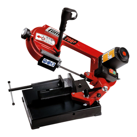
Femi 780P Specification sheet

Femi
Femi 780P Specification sheet
Femi
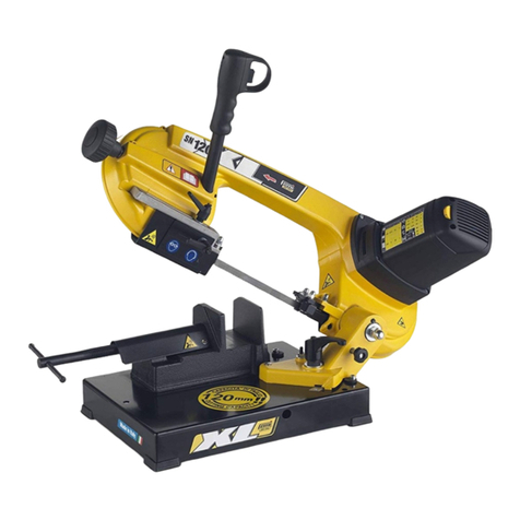
Femi NG120XL User manual
Femi
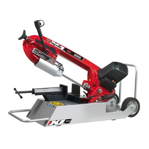
Femi 787XL Specification sheet
Femi
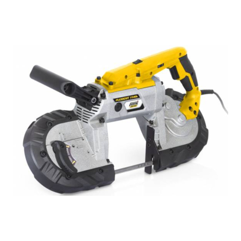
Femi job FLEXICUT 1140E User manual
Femi
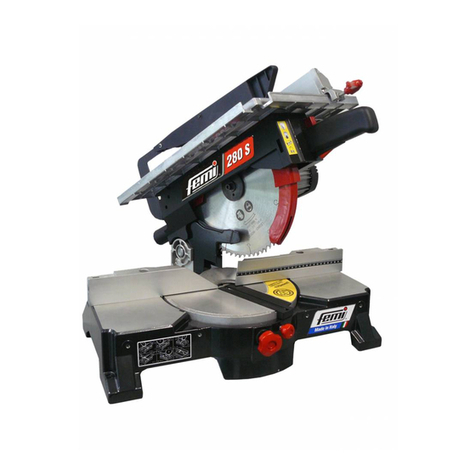
Femi 280 Specification sheet
Femi
Femi TR 305-i User manual

Femi
Femi 2201 SPECIAL Specification sheet
Popular Saw manuals by other brands

Thomas
Thomas CUT 250 1 PH Use and maintenance manual
EINHELL
EINHELL TH-CS 1200/1 Original operating instructions
Craftsman
Craftsman 113.24250 owner's manual
stayer
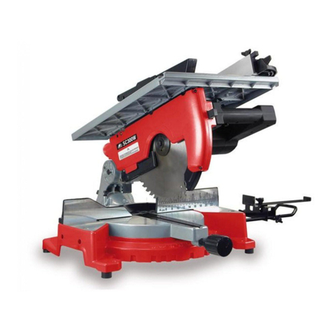
stayer SC300W operating instructions

Black & Decker
Black & Decker Portable band saws owner's manual

Titan
Titan SF10N1 Safety and operating manual

