manuals.online logo
Brands
  1. Home
  2. •
  3. Brands
  4. •
  5. Bosch
  6. •
  7. Control Unit
  8. •
  9. Bosch DS7461i User manual

Bosch DS7461i User manual

Installation manual
for the
DS7461i Single Zone Input Module
1.0 Description
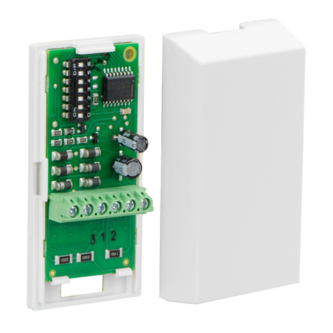
The DS7461i is a Single Zone Input Module designed to operate with compatible multiplex systems. It provides a supervised input
zone for connection of conventional normally open or normally closed inputs. Each DS7461i occupies one multiplex zone address on
the system. The DS7461i connects to the DS7430, DS7436 Multiplex Expansion Modules or the D8125MUX Multiplex Expansion
Module. For additional DS7461i installation information, refer to the D9412GV2/D7412GV2 Approved Applications Compliance Guide
(P/N: F01U003639).
2.0 Specifications
•Voltage: 12 VDC nominal
•Current : 0.5 mA maximum
•Line Impedance:
Maximum Impedance: 4.05Ωat +68°F (+20°C) nominal
Maximum Distance Size
250 ft 22 AWG
600 ft 18 AWG
76 m 0.65 mm
193 m 1.02 mm
Fire applications require 18 AWG.
•Operating Temperature Range: +32°F to +122°F (0°C to +50°
C)
•Relative Humidity: 0to93%
•Signaling Line Circuit: Class B
•Initiating Circuit: ClassB
When used in a fire system, NFPA 72 prohibits this product from sharing a communications bus with non-fire devices.
3.0 Programming
Refer to the control panel's installation guide for multiplex zone (point) programming information.
Refer to Section 6.0 on page 3 for switch settings.
4.0 Installation
After any programming or hardware change, do a functional test of the system as required by local codes.
These instructions assume that the control panel is installed and in proper working condition.
The control panel must be programmed and the DS7461i address switches must be set for the DS7461i to operate.
• Program the control panel as described in the control panel's reference guide.
Disconnect power to the control panel before routing wires to connect the DS7461i.
Page 2 © Bosch Security Systems B.V., 2020 DS7461i Installation Guide
• Remove the cover of the DS7461i. Press in and up with your thumb and nail directly above the lip of the DS7461i (refer to Figure 1).
Figure1:RemovingtheCover
• Remove the DS7461i circuit board from the base. Press the circuit board retainer tab and pull the circuit board up and out of the base
(refer to Figure 2).
Wire
Entrance
Terminal Strip
Circuit Board
Retainer Tab
Reed Switch
Address
Switches
1 2 3 4 5 6 7 8
O
N
Tamper
Switch
Figure2: Removing the PCB
Handle this and all circuit boards carefully. Hold the board by its edges.
• Route the wiring through the wire entrance of the DS7461i base.
• Mount the DS7461i base to the mounting surface using the supplied screws.
• Return the DS7461i circuit board to the base.
5.0 Wiring DS7461i Terminals Description
Bus + Positive Multiplex Input
Bus - Negative Multiplex Input
1 Input Zone Positive Input
G Input Zone Ground
Table 1: DS7461i Terminal Descriptions
• Connect wiring to the DS7461i as shown in Figure 3 and Figure 4.
• Input zones are designed to monitor Normally Open or Normally Closed dry contacts. They are supervised using 47K ohm end-of-
line resistors.
The protection zone can be used as a magnetic contact by mounting a magnet iwith the reed switch and removing the EOL
resistor for the protection zone. The protection zone cannot be used as a magnetic contact and used to monitor other
contacts at the same time.
• If the reed switch is not being used, cutting it from the DS7461i circuit board prevents possible tampering to override Zone 1
operation.
• For fire installations, order Multiplex Fire Zone EOL P/N 28010 in the quantity needed.
The input zones are power limited and supervised.
When used in fire applications, Normally Open contacts must be used on the input zones.
DS7461i Installation Guide © Bosch Security Systems B.V., 2020 Page 3
5.1 DS7430 Multiplex Expansion Module Wiring
Note: Do not loop wires around the terminals.
DS7461i
Ground
Zone 1+
Multiplex Bus -
Multiplex Bus +
DS7430
Power Bus
N/C
N/O
Use 47K ohm EOL P/N:26069
for non-fire applications.
Use 47K ohm EOL P/N:28010
for fire applications.
Alarm Contact
(Normally Open or
Normally Closed)
Figure 3: Wiring to a DS7430 Multiplex Expansion Module
5.2 DS7436 Multiplex Expansion Module Wiring
DS7461i
Ground
Zone 1+
Multiplex Bus -
Multiplex Bus +
DS7436
N/C
N/O
Use 47K ohm EOL P/N:26069
for non-fire applications.
Use 47K ohm EOL P/N:28010
for fire applications.
Either Bus A or Bus B,
or both, may be used. Refer
to the panel’s reference guide.
PWR+ PWR- BUS+ BUS- PWR+ PWR- BUS+ BUS-
Figure 4: Wiring to a DS7436 Multiplex Expansion Module
5.2 D8125MUX Multiplex Expansion Module Wiring
D8125 Multiplex Module
POWERA MUX BUS A POWER B MUX BUS B
+- +- + - +-
Either Bus A or Bus B,
or both, may be used. Refer
to the panel’s reference guide.
DS7461i
Ground
Zone 1+
Multiplex Bus -
Multiplex Bus +
N/C
N/O
Use 47K ohm EOL P/N:26069
for non-fire applications.
Use 47K ohm EOL P/N:28010
for fire applications.
Alarm Contact
(Normally Open or
Normally Closed)
Figure 5: Wiring to a D8125MUX Multiplex Expansion Module
6.0 Switch Settings
Set the address switch settings before connecting the DS7461i to the multiplex bus.
No two DS7461i Single Zone modules may be set to the same address. Having
two or more units set to the same address may prevent fault detection or cause
multiplex bus failure.
You can find the Address Switch Settings using the chart on the last page,
or by calculating the decimal number of the address.
Binary Switch Values (Point 17 shown)
O
N1234 56 78
128 64 32 16 8 4 2 1
The DS7400 Series control panels cannot be programmed for zone (point) addresses 001-008.
In the switch
settings chart
= ON
Address
Switches
1 2 3 4 5 6 7 8
O
N
1 2 3 4 5 6 7 8
O
N
001
002
003
004
005
006
007
008
009
010
011
012
013
014
015
016
017
018
019
020
021
022
023
024
025
026
027
028
029
030
031
032
033
034
035
036
037
038
039
040
041
042
043
044
045
046
047
048
049
050
051
052
053
054
055
056
057
058
059
060
061
062
063
064
1 2 3 4 5 6 7 8
ZONE
(POINT)
ADDRESS SWITCH NUMBER
= SWITCH ON
(CLOSED)
065
066
067
068
069
070
071
072
073
074
075
076
077
078
079
080
081
082
083
084
085
086
087
088
089
090
091
092
093
094
095
096
097
098
099
100
101
102
103
104
105
106
107
108
109
110
111
112
113
114
115
116
117
118
119
120
121
122
123
124
125
126
127
128
1 2 3 4 5 6 7 8
ZONE
(POINT)
ADDRESS SWITCH NUMBER
= SWITCH ON
(CLOSED)
129
130
131
132
133
134
135
136
137
138
139
140
141
142
143
144
145
146
147
148
149
150
151
152
153
154
155
156
157
158
159
160
161
162
163
164
165
166
167
168
169
170
171
172
173
174
175
176
177
178
179
180
181
182
183
184
185
186
187
188
189
190
191
192
1 2 3 4 5 6 7 8
ZONE
(POINT)
ADDRESS SWITCH NUMBER
= SWITCH ON
(CLOSED)
193
194
195
196
197
198
199
200
201
202
203
204
205
206
207
208
209
210
211
212
213
214
215
216
217
218
219
220
221
222
223
224
225
226
227
228
229
230
231
232
233
234
235
236
237
238
239
240
241
242
243
244
245
246
247
248
249
250
251
252
253
254
255
1 2 3 4 5 6 7 8
ZONE
(POINT)
ADDRESS SWITCH NUMBER
= SWITCH ON
(CLOSED)
©Bosch Security Systems B.V., 2020
Torenallee 49, 5617 BA Eindhoven, Netherlands
2020.04
DS7461i Installation Instructions
P/N: F01U071298-04Page 4

Other Bosch Control Unit manuals

Bosch rexroth PSK Gen 2 User manual

Bosch

Bosch rexroth PSK Gen 2 User manual

Bosch ReadykeyPRO LNL-1200 User manual

Bosch

Bosch ReadykeyPRO LNL-1200 User manual

Bosch C-IR 20 User manual

Bosch

Bosch C-IR 20 User manual

Bosch ISM 1 User manual

Bosch

Bosch ISM 1 User manual

Bosch D9127U User manual

Bosch

Bosch D9127U User manual

Bosch REXROTH DBD User manual

Bosch

Bosch REXROTH DBD User manual

Bosch SE352 User manual

Bosch

Bosch SE352 User manual

Bosch D9133TTL-E User manual

Bosch

Bosch D9133TTL-E User manual

Bosch Rexroth IndraControl VCP 20.2 Technical manual

Bosch

Bosch Rexroth IndraControl VCP 20.2 Technical manual

Bosch Rexroth IndraControl VPB 40.4 User manual

Bosch

Bosch Rexroth IndraControl VPB 40.4 User manual

Bosch D192G User manual

Bosch

Bosch D192G User manual

Bosch Rexroth IndraDrive CSB02 Technical manual

Bosch

Bosch Rexroth IndraDrive CSB02 Technical manual

Bosch Rexroth WMM6 Series User manual

Bosch

Bosch Rexroth WMM6 Series User manual

Bosch B426 Operating instructions

Bosch

Bosch B426 Operating instructions

Bosch D7039 User manual

Bosch

Bosch D7039 User manual

Bosch KTS 5 Series User manual

Bosch

Bosch KTS 5 Series User manual

Bosch DS7432 User manual

Bosch

Bosch DS7432 User manual

Bosch Control 8313 Instruction Manual

Bosch

Bosch Control 8313 Instruction Manual

Bosch Rexroth 4WRPD User manual

Bosch

Bosch Rexroth 4WRPD User manual

Bosch Rexroth LFA DB Series User manual

Bosch

Bosch Rexroth LFA DB Series User manual

Bosch Rexroth ctrlX CORE plus X3 User manual
Bosch

Bosch Rexroth ctrlX CORE plus X3 User manual

Bosch Rexroth M4-12 Operating instructions

Bosch

Bosch Rexroth M4-12 Operating instructions

Bosch Rexroth IndraControl L10 Technical manual
Bosch

Bosch Rexroth IndraControl L10 Technical manual

Bosch SE352 User manual

Bosch

Bosch SE352 User manual

Popular Control Unit manuals by other brands

CALEFFI Altecnic SATK40103 Installation, operation & maintenance instructions

CALEFFI

CALEFFI Altecnic SATK40103 Installation, operation & maintenance instructions

Eagle tree OSD pro Instruction manuals

Eagle tree

Eagle tree OSD pro Instruction manuals

MINEW MinewSemi MS50SF7 manual

MINEW

MINEW MinewSemi MS50SF7 manual

SPL De-Esser 500 Series manual

SPL

SPL De-Esser 500 Series manual

Rutenbeck UM-Cat.6A iso installation instructions

Rutenbeck

Rutenbeck UM-Cat.6A iso installation instructions

Lenze EPM-H502 operating instructions

Lenze

Lenze EPM-H502 operating instructions

GE Becker 3.5M Series instruction manual

GE

GE Becker 3.5M Series instruction manual

Siemens SINAMICS G120 PM240-2 Getting started guide

Siemens

Siemens SINAMICS G120 PM240-2 Getting started guide

DAQ system NET-FRM01 user manual

DAQ system

DAQ system NET-FRM01 user manual

Harvia C400VKK manual

Harvia

Harvia C400VKK manual

Allen-Bradley ControlLogix 1756-OV32E installation instructions

Allen-Bradley

Allen-Bradley ControlLogix 1756-OV32E installation instructions

M-system R3-RS8 instruction manual

M-system

M-system R3-RS8 instruction manual

CLA-VAL 90-48 Installation operation & maintenance

CLA-VAL

CLA-VAL 90-48 Installation operation & maintenance

Bogen NYQUIST NQ-GA10P Configuration guide

Bogen

Bogen NYQUIST NQ-GA10P Configuration guide

CAME TOP Series quick start guide

CAME

CAME TOP Series quick start guide

Xytronix Research & Design ControlByWeb X317 user manual

Xytronix Research & Design

Xytronix Research & Design ControlByWeb X317 user manual

Casit KEQS10 manual

Casit

Casit KEQS10 manual

EMS ZITON RADIO LOOP MODULE Programming manual

EMS

EMS ZITON RADIO LOOP MODULE Programming manual

manuals.online logo
manuals.online logoBrands
  • About & Mission
  • Contact us
  • Privacy Policy
  • Terms and Conditions

Copyright 2025 Manuals.Online. All Rights Reserved.