manuals.online logo
Brands
  1. Home
  2. •
  3. Brands
  4. •
  5. Monacor
  6. •
  7. Control Unit
  8. •
  9. Monacor MPA-1 User manual

Monacor MPA-1 User manual

C 3
470 p
C 1
22 µ
INPUT
OUTPUT
C 2
100 µ
R 6
150
VR 1
10 k
R 5
10 k
R 3
100
R 4
221 k
R 2
56 k2
R 1
100 k
IC 1
TL 071
7
4
6
2
3
R 7
681
R 8
22 k1
5
1
8
R 9
1k
R 10
47 k5
D 1
BZX55C10
C 4
22 µ
R 11
4 k75
TR 1
BC 549
D 2
BZX55C15
TR 2
TIP 122
R 12
27 k4
C 6
10 µ
+U 12 – 40 V
C 5
100 µ
9 V
C7
330n
C7
330n
ELECTRONICS FOR SPECIALISTS ELECTRONICS FOR SPECIALISTS ELECTRONICS FOR SPECIALISTS ELECTRONICS FOR SPECIALISTS ELECTRONICS FOR SPECIALISTS ELECTRONICS
MPA-1
Bestell-Nr. • Order No. 32.0550
MONACOR INTERNATIONAL GmbH & Co. KG • Zum Falsch 36 • 28307 Bremen • Germany
Copyright©by MONACOR INTERNATIONAL. All rights reserved. A-0989.99.04.03.2017
➁
➀
Input Output TR 2
VR 1
IC 1
1 4
8 5 +U
MONACOR MPA-1
C 2
12 – 40 V
Mic Line
S/N ratio: � � � � � � � � � � � � � � �> 65 dB
THD: � � � � � � � � � � � � � � � � � � �< 0�05 %
Noise voltage: � � � � � � � � � � � �0�5 µV
Power supply: � � � � � � � � � � � �12 – 40 V (⎓)/6 mA
Admissible
operating temperature: � � � � �0 – 40 °C
Dimensions
w/o axle (W × H × D): � � � � � �40 × 25 × 60 mm
Weight:� � � � � � � � � � � � � � � � �30 g
Subject to technical modification.
Störabstand: � � � � � � � � � � � � �> 65 dB
Klirrfaktor:� � � � � � � � � � � � � � �< 0,05 %
Rauschspannung: � � � � � � � � �0,5 µV
Stromversorgung: � � � � � � � � �12 – 40 V (⎓)/6 mA
Zulässige Einsatztemperatur: �0 – 40 °C
Abmessungen
ohne Achse (B × H × T):� � � � �40 × 25 × 60 mm
Gewicht: � � � � � � � � � � � � � � � �30 g
Änderungen vorbehalten.
Microphone Preamplifier Module
These instructions are intended for users with basic
electronic knowledge� Please read the instructions
carefully prior to operation and keep them for later
reference�
1 Applications
Via the module MPA-1, a microphone can be con-
nected to the Line input of an audio unit. With a
corresponding voltage supply, the microphone pre-
amplifier can be operated as an individual unit or
placed as a module into an audio unit (e.g. amplifier,
mixer, etc.). For operation, a DC voltage of 12– 40 V
is required. The current consumption is 6mA.
2 Important Notes
The module corresponds to all relevant directives of
the EU and is therefore marked with .
•
The module has been designed in accordance
with the EMC Directive 2014/30/EU (EMC = elec-
tromagnetic compatibility). To ensure compliance
with this directive also during operation, place the
module in a shielded housing and connect its input
and its output via shielded cables. If the module
does not comply with the EMC directive, the
declaration of conformity will be invalid.
•
The module is only suitable for indoor use. Protect
it against dripping water and splash water, high air
humidity and heat (admissible ambient tempera-
ture range 0– 40°C).
•
No guarantee claims for the module and no liabil-
ity for any resulting personal damage or material
damage will be accepted if the module is used
for other purposes than originally intended, if it is
not correctly connected, if it is overloaded or not
repaired in an expert way.
If the module is to be put out of operation
definitively, take it to a local recycling plant
for a disposal which is not harmful to the
environment.
3 Connection
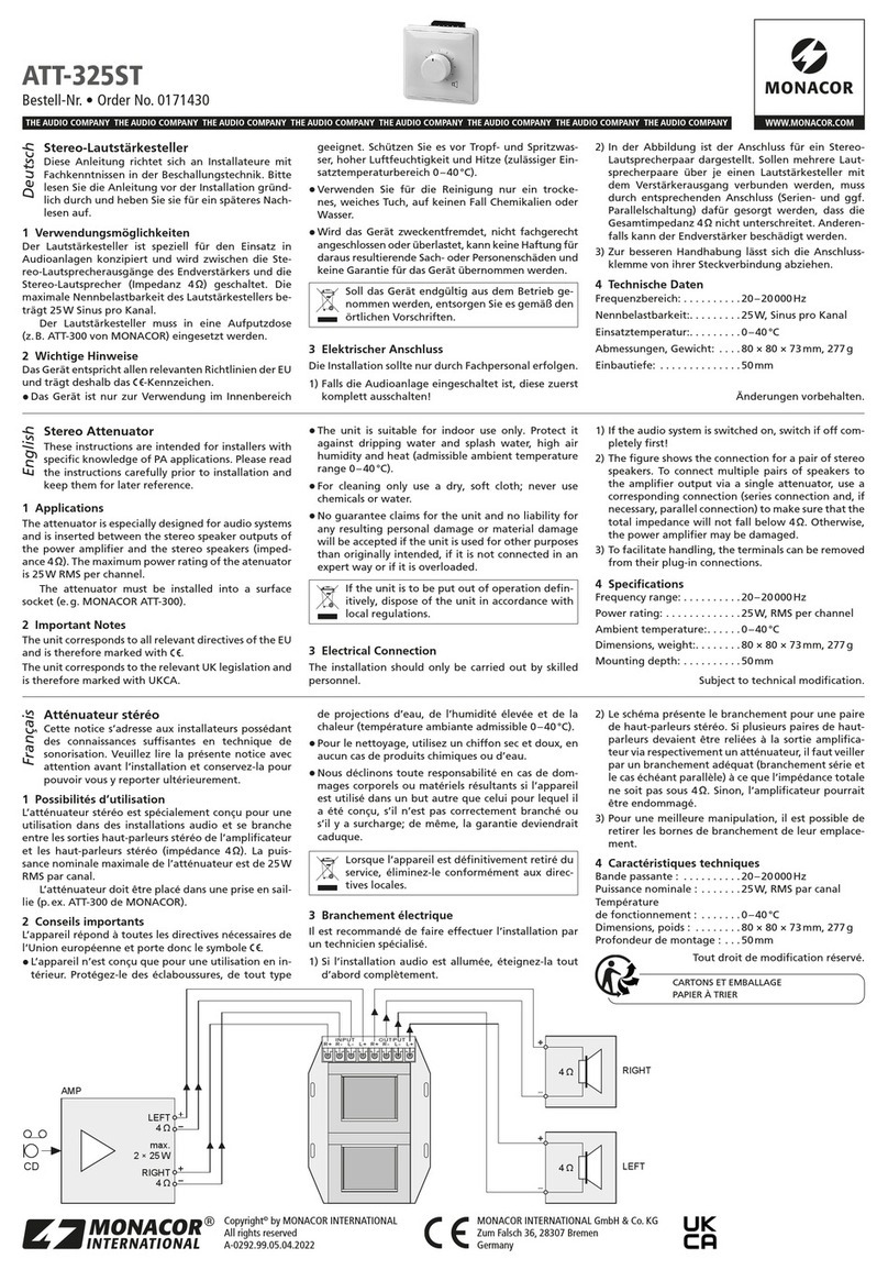
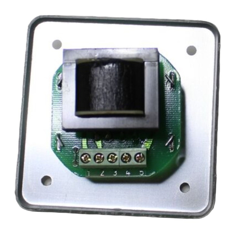
The complete connection is shown in fig. 1:
INPUT signal input, connection for the microphone
⊥ground for the microphone
OUTPUT output
⊥ground for the output
+U operating voltage 12– 40V (⎓)
⊥ground for the operating voltage
4 Setting the Module into Operation
After connecting the supply voltage, the microphone
preamplifier is ready for operation. Adjust the micro-
phone volume with the built-in control. Make sure
not to overload the subsequent unit.
5 Specifications
Frequency range: � � � � � � � � � �20 – 15 000 Hz, −0�5 dB
15 – 20 000 Hz, −3�0 dB
Input sensitivity: � � � � � � � � � �2 mV with 0 dB
at theoutput
Input impedance:� � � � � � � � � �200 Ω – 10 kΩ
Output voltage: � � � � � � � � � � �7 V max�/1 kΩ
Gain:� � � � � � � � � � � � � � � � � � �52 dB
Mikrofonvorverstärker-Modul
Diese Anleitung richtet sich an Anwender mit
Grundkenntnissen in der Elektronik� Bitte lesen Sie
die Anleitung vor dem Betrieb gründlich durch und
heben Sie sie für ein späteres Nachlesen auf�
1 Verwendungsmöglichkeiten
Über das Modul MPA-1 lässt sich ein Mikrofon an
einen Line-Eingang eines Audiogerätes anschlie-
ßen. Der Mikrofonvorverstärker kann mit einer ent-
sprechenden Spannungsversorgung als Einzelgerät
aufgebaut oder als Modul in ein Audiogerät (z.B.
Verstärker, Mischpult etc.) eingesetzt werden. Zum
Betrieb wird eine Gleichspannung von 12– 40V be-
nötigt. Die Stromaufnahme beträgt 6mA.
2 Wichtige Hinweise für den Gebrauch
Das Modul entspricht allen relevanten Richtlinien der
EU und trägt deshalb das -Zeichen.
•
Das Modul ist nach der EMV-Richtlinie 2014/30/EU
aufgebaut (EMV = Elektromagnetische Verträglich-
keit). Damit das Modul auch im Betrieb diese Richt-
linie erfüllt, muss es in ein abgeschirmtes Gehäuse
eingesetzt werden und der Eingang sowie der Aus-
gang müssen über abgeschirmte Leitungen ange-
schlossen werden. Wird die EMV-Richtlinie nicht
eingehalten, erlischt die Konformitätserklärung.
•
Verwenden Sie das Modul nur im Innenbereich.
Schützen Sie ihn vor Tropf- und Spritzwasser, hoher
Luftfeuchtigkeit und Hitze (zulässiger Einsatztem-
peraturbereich 0– 40°C).
•
Wird das Modul zweckentfremdet, nicht richtig
angeschlossen, überlastet oder nicht fachgerecht
repariert, kann keine Haftung für daraus resultie-
rende Sach- oder Personenschäden und keine Ga-
rantie für das Modul übernommen werden.
Soll das Modul endgültig aus dem Betrieb
genommen werden, übergeben Sie es zur
umweltgerechten Entsorgung einem ört-
lichen Recyclingbetrieb.
3 Anschluss
Der komplette Anschluss ist in der Abb. 1 dargestellt:
INPUT Signaleingang, Anschluss für das Mikrofon
⊥Masse für das Mikrofon
OUTPUT Ausgang
⊥Masse für den Ausgang
+U Betriebsspannung 12– 40V (⎓)
⊥Masse für die Betriebsspannung
4 Inbetriebnahme
Nach dem Anlegen der Versorgungsspannung ist der
Mikrofonvorverstärker betriebsbereit. Mit dem ein-
gebauten Regler die Mikrofonlautstärke einstellen.
Dabei darf das nachfolgende Gerät nicht übersteuert
werden.
5 Technische Daten
Frequenzbereich: � � � � � � � � � �20 – 15 000 Hz, −0,5 dB
15 – 20 000 Hz, −3,0 dB
Eingangsempfindlichkeit: � � � �2 mV bei 0 dB am Ausgang
Eingangsimpedanz: � � � � � � � �200 Ω – 10 kΩ
Ausgangsspannung:� � � � � � � �7V max�/1 kΩ
Verstärkung: � � � � � � � � � � � � �52 dB
DeutschEnglish
ELECTRONICS FOR SPECIALISTS ELECTRONICS FOR SPECIALISTS ELECTRONICS FOR SPECIALISTS ELECTRONICS FOR SPECIALISTS ELECTRONICS FOR SPECIALISTS ELECTRONICS
MONACOR INTERNATIONAL GmbH & Co. KG • Zum Falsch 36 • 28307 Bremen • Germany
Copyright©by MONACOR INTERNATIONAL. All rights reserved. A-0989.99.04.03.2017
MPA-1
Réferénce num. • Codice 32.0550
C 3
470 p
C 1
22 µ
INPUT
OUTPUT
C 2
100 µ
R 6
150
VR 1
10 k
R 5
10 k
R 3
100
R 4
221 k
R 2
56 k2
R 1
100 k
IC 1
TL 071
7
4
6
2
3
R 7
681
R 8
22 k1
5
1
8
R 9
1k
R 10
47 k5
D 1
BZX55C10
C 4
22 µ
R 11
4 k75
TR 1
BC 549
D 2
BZX55C15
TR 2
TIP 122
R 12
27 k4
C 6
10 µ
+U 12 – 40 V
C 5
100 µ
9 V
C7
330n
C7
330n
➁
➀
Input Output TR 2
VR 1
IC 1
1 4
8 5 +U
MONACOR MPA-1
C 2
12 – 40 V
Mic Line
Modulo preamplificatore
permicrofono
Queste istruzioni sono rivolte all’utente con cono-
scenze base elettroniche� Vi preghiamo di leggerle
attentamente prima dell’installazione e di conser-
varle per un uso futuro�
1 Possibilità d’impiego
Il modulo MPA-1 permette di collegare un microfono
con l’ingresso Line di un apparecchio audio. Il mo-
dulo può funzionare, insieme ad un alimentatore de
rete, come unità singola, oppure può essere montato
in un apparecchio audio (p.es. amplificatore, mixer
ecc.). Come alimentazione occorre una tensione con-
tinua di 12–40 V; l’assorbimento è di 6 mA.
2 Avvisi importanti per l’uso
Il modulo è conforme a tutte le direttive rilevanti
dell’UE e pertanto porta la sigla
•
Questomodulocorrispondealladirettiva2014/30/UE
sulla compatibilità elettromagnetica CEM. Per
rispettare tali criteri anche durante il funziona-
mento, il modulo deve essere inserito in un con-
tenitore schermato, e l’ingresso e l’uscita devono
essere collegati con cavi schermati. Se non si
rispetta la direttiva CEM, la dichiarazione di confor-
mità perde il suo valore.
•
Far funzionare il modulo solo all’interno di locali.
Proteggerlo dall’acqua gocciolante e dagli spruzzi
d’acqua, da alta umidità dell’aria e dal calore (tem-
peratura d’impiego ammessa fra 0 e 40°C).
•
Nel caso d’uso improprio, di collegamento sba-
gliato, di sovraccarico o di riparazione non a
regola d’arte del modulo, non si assume nessuna
responsabilità per eventuali danni consequenziali a
persone o a cose e non si assume nessuna garanzia
per il modulo.
Se si desidera eliminare il modulo definitiva-
mente, consegnarlo per lo smaltimento ad
un’istituzione locale per il riciclaggio.
3 Collegamento
La figura 1 illustra tutti i collegamenti:
INPUT ingresso segnale, da collegare con
ilmicrofono
⊥massa del microfono
OUTPUT uscita
⊥massa dell’uscita
+U tensione d’esercizio 12–40 V (⎓)
⊥massa della tensione d’esercizio
4 Messa in funzione
Dopo aver applicata la tensione d’alimentazione, il
preamplificatore per microfono è pronto per l’uso.
Con il regolatore del modulo si può impostare il
volume del microfono, faccendo attenzione a non
sovrapilotare l’apparecchio a valle.
5 Dati tecnici
Banda passante: � � � � � � � � � �20 – 15 000 Hz, −0,5 dB
15 – 20 000 Hz, −3,0 dB
Sensibilità d’ingresso: � � � � � �2 mV con 0 dB all’uscita
Impedenza d’ingresso: � � � � � �200 Ω – 10 kΩ
Tensione d’uscita: � � � � � � � � �7V max�/1 kΩ
Amplificazione: � � � � � � � � � � �52 dB
Rapporto S/R: � � � � � � � � � � � �> 65 dB
Fattore di distorsione: � � � � � �< 0,05 %
Tensione di rumore: � � � � � � � �0,5 µV
Alimentazione: � � � � � � � � � � �12 – 40 V (⎓)/6 mA
Temperatura d’impiego
ammessa: � � � � � � � � � � � � � � �0 – 40 °C
Dimensioni
senza asse (l × h × p):� � � � � �40 × 25 × 60 mm
Peso:� � � � � � � � � � � � � � � � � � �30 g
Con riserva di modifiche tecniche.
Module préamplificateur
pourmicrophone
Cette notice s’adresse aux utilisateurs avec connais-
sance de base eléctroniques�Veuillez lire la présente
notice avec attention avant le fonctionnement et
conservez-la pour pouvoir vous y reporter ultérieu-
rement�
1 Possibilités d’utilisation
Le module MPA-1 permet de brancher un micro-
phone à une entrée Line d’un appareil audio. Avec
une alimentation correspondante, le préamplificateur
peut fonctionner comme appareil individuel ou être
inséré comme module dans un appareil audio (par
exemple, amplificateur, table de mixage ...). Une ali-
mentation DC de 12–40 V est nécessaire, la consom-
mation est de 6mA.
2 Conseils importants d’utilisation
Le module répond à toutes les directives nécessaires
de l’Union européenne et porte donc le symbole .
•
Le module répond à la directive 2014/30/UE re-
lative à la compatibilité électromagnétique. Pour
qu’il réponde à cette directive pendant le fonction-
nement, l’appareil doit être placé dans un boîtier
blindé, l’entrée et la sortie doivent être reliées
par des câbles blindés. En cas de non respect de
cette directive, l’appareil ne saurait être reconnu
conforme.
•
Le module n’est conçu que pour une utilisation en
intérieur. Protégez-le des éclaboussures, de tout type
de projections d’eau, d’une humidité élevée et de la
chaleur (température ambiante admissible 0–40 °C).
•
Nous déclinons toute responsabilité en cas de
dommages corporels ou matériels résultants si le
module est utilisé dans un but autre que celui pour
lequel il a été conçu, s’il n’est pas correctement
branché, s’il y a surcharge ou s’il n’est pas réparé
par une personne habilitée ; en outre, la garantie
deviendrait caduque.
Lorsque le module est définitivement retiré
du service, vous devez le déposer dans une
usine de recyclage de proximité pour contri-
buer à son élimination non polluante.
CARTONS ET EMBALLAGE
PAPIER À TRIER
3 Branchements
Le schéma 1 présente tous les branchements à
effectuer :
INPUT
entrée du signal, branchement pour le micro
⊥masse pour le micro
OUTPUT sortie
⊥masse pour la sortie
+U tension de fonctionnement 12– 40V (⎓)
⊥masse pour la tension de fonctionnement
4 Mise en service
Une fois le préamplificateur mis sous tension, il est
prêt à fonctionner. Utilisez le réglage pour adapter
le volume du microphone ; veillez à éviter toute sur-
charge de l’appareil suivant.
5 Caractéristiques techniques
Bande passante :� � � � � � � � � �20 – 15 000 Hz, −0,5 dB
15 – 20 000 Hz, −3,0 dB
Sensibilité d’entrée : � � � � � � �2 mV à 0 dB en sortie
Impédance d’entrée :� � � � � � �200 Ω – 10 kΩ
Tension de sortie : � � � � � � � � �7V max�/1 kΩ
Amplification :� � � � � � � � � � � �52 dB
Rapport signal/bruit :� � � � � � �> 65 dB
Taux de distorsion : � � � � � � � �< 0,05 %
Tension de ronflement : � � � � �0,5 µV
Alimentation : � � � � � � � � � � � �12 – 40 V (⎓)/6 mA
Température autorisée de
fonctionnement : � � � � � � � � � �0 – 40 °C
Dimensions
sans axe (L × H × P) : � � � � � �40 × 25 × 60 mm
Poids :� � � � � � � � � � � � � � � � � �30 g
Tout droit de modification réservé.
FrançaisItaliano
This manual suits for next models

1

Other Monacor Control Unit manuals

Monacor ATT-1950 User manual

Monacor

Monacor ATT-1950 User manual

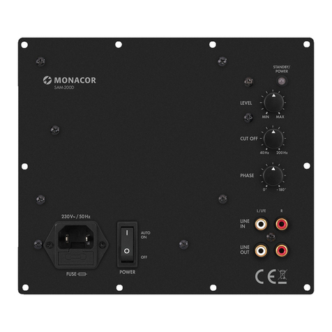
Monacor SAM-200D User manual

Monacor

Monacor SAM-200D User manual

Monacor img Stage Line DIB-100 User manual

Monacor

Monacor img Stage Line DIB-100 User manual

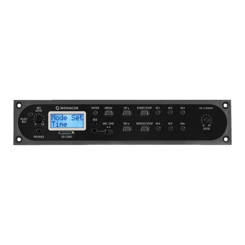
Monacor PA-1120DMT User manual

Monacor

Monacor PA-1120DMT User manual

Monacor ATT-210/WS User manual

Monacor

Monacor ATT-210/WS User manual

Monacor VCA-202R User manual

Monacor

Monacor VCA-202R User manual

Monacor DN-1218P User manual

Monacor

Monacor DN-1218P User manual

Monacor PA-1200EX User manual

Monacor

Monacor PA-1200EX User manual

Monacor MPA-1 User manual

Monacor

Monacor MPA-1 User manual

Monacor ATT-1950 User manual

Monacor

Monacor ATT-1950 User manual

Monacor TVCCD-38MCOL User manual

Monacor

Monacor TVCCD-38MCOL User manual

Monacor ATT-325ST User manual

Monacor

Monacor ATT-325ST User manual

Monacor PA TXA-802MT User manual

Monacor

Monacor PA TXA-802MT User manual

Monacor PA-1200EX User manual

Monacor

Monacor PA-1200EX User manual

Monacor ATT-1935 User manual

Monacor

Monacor ATT-1935 User manual

Monacor ATT-506PEU User manual

Monacor

Monacor ATT-506PEU User manual

Monacor PA ATT-325ST User manual

Monacor

Monacor PA ATT-325ST User manual

Monacor DMP-100R User manual

Monacor

Monacor DMP-100R User manual

Monacor img Stage Line TXS-820M User manual

Monacor

Monacor img Stage Line TXS-820M User manual

Monacor ATT-210P/WS User manual

Monacor

Monacor ATT-210P/WS User manual

Monacor ATT-306PEU User manual

Monacor

Monacor ATT-306PEU User manual

Monacor ATT-212/WS User manual

Monacor

Monacor ATT-212/WS User manual

Monacor PA ATT-235/WS User manual

Monacor

Monacor PA ATT-235/WS User manual

Monacor ATT-212/WS User manual

Monacor

Monacor ATT-212/WS User manual

Popular Control Unit manuals by other brands

Schmidt Press Control 3000 quick start guide

Schmidt

Schmidt Press Control 3000 quick start guide

Festo CPE PRS Series operating instructions

Festo

Festo CPE PRS Series operating instructions

GRAUPNER S1038 manual

GRAUPNER

GRAUPNER S1038 manual

Siemens SIMATIC S7-400H manual

Siemens

Siemens SIMATIC S7-400H manual

resideo Braukmann D05FT installation instructions

resideo

resideo Braukmann D05FT installation instructions

OJ Electronics WLM3-1AO instructions

OJ Electronics

OJ Electronics WLM3-1AO instructions

Polytron SPM-T2CT user manual

Polytron

Polytron SPM-T2CT user manual

GESTRA AK 45 Retrofitting Instructions

GESTRA

GESTRA AK 45 Retrofitting Instructions

Extron electronics IRCM-DVplus Setup guide

Extron electronics

Extron electronics IRCM-DVplus Setup guide

BC Acoustique EX PHONO 2X Quick installation guide

BC Acoustique

BC Acoustique EX PHONO 2X Quick installation guide

Nordelettronica NE205 11 instruction manual

Nordelettronica

Nordelettronica NE205 11 instruction manual

VIEWEG DV-5625 Series operating manual

VIEWEG

VIEWEG DV-5625 Series operating manual

MX Atmos Select Fitting instructions

MX

MX Atmos Select Fitting instructions

M-system R7M-EC8A instruction manual

M-system

M-system R7M-EC8A instruction manual

DMX4ALL PixxRangeExtender 5V manual

DMX4ALL

DMX4ALL PixxRangeExtender 5V manual

Honeywell CentraLine CLCM1T installation instructions

Honeywell

Honeywell CentraLine CLCM1T installation instructions

Stahl ConSig 8453 operating instructions

Stahl

Stahl ConSig 8453 operating instructions

Paul TAC4 DG + TCP Installation and Maintenance

Paul

Paul TAC4 DG + TCP Installation and Maintenance

manuals.online logo
manuals.online logoBrands
  • About & Mission
  • Contact us
  • Privacy Policy
  • Terms and Conditions

Copyright 2025 Manuals.Online. All Rights Reserved.