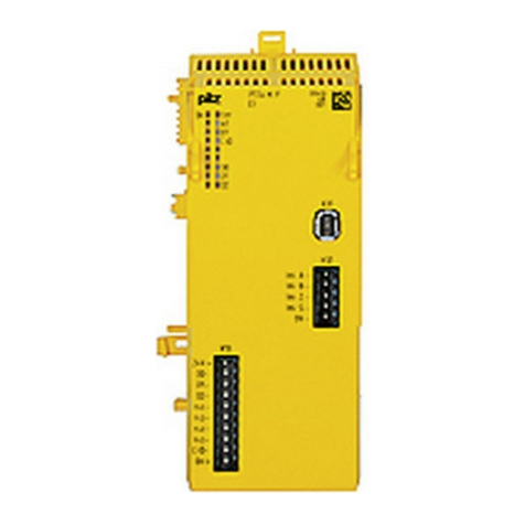
Pilz PSSu K F EI CV User manual

PSSu K F EI CV(-T)
Operating Manual-1004290-EN-04
}Decentralised system PSSuniversal I/O

Preface
This document is the original document.
All rights to this documentation are reserved by Pilz GmbH & Co. KG. Copies may be made
for the user's internal purposes. Suggestions and comments for improving this documenta-
tion will be gratefully received.
Source code from third-party manufacturers or open source software has been used for
some components. The relevant licence information is available on the Internet on the Pilz
homepage.
Pilz®, PIT®, PMI®, PNOZ®, Primo®, PSEN®, PSS®, PVIS®, SafetyBUS p®,
SafetyEYE®, SafetyNET p®, the spirit of safety® are registered and protected trademarks
of Pilz GmbH & Co. KG in some countries.
SD means Secure Digital

Contents
Operating Manual PSSu K F EI CV(-T)
1004290-EN-04 3
Section 1 Introduction 6
1.1 Validity of documentation 6
1.1.1 Retaining the documentation 6
1.1.2 Terminology: System environment A and B 6
1.2 Definition of symbols 7
Section 2 Overview 8
2.1 Module features 8
2.2 Front view 9
Section 3 Safety 10
3.1 Intended use 10
3.2 Safety regulations 11
3.2.1 Use of qualified personnel 11
3.2.2 Warranty and liability 11
3.2.3 Disposal 11
Section 4 Function description 12
4.1 Module and periphery supply 12
4.2 FS outputs 12
4.2.1 Single-pole outputs 12
4.2.2 Notes 14
4.3 ST output 14
4.4 Cascading 14
4.5 Monitoring functions 16
4.5.1 Safe speed monitoring - SSM 17
4.5.2 Safe speed range monitoring - SSR-M 19
4.5.3 Safe operating stop monitoring SOS-M 21
4.5.4 Safe direction monitoring SDI-M 23
4.5.5 Activation of safety function SS1 on a servo amplifier 25
4.5.5.1 Reaction on SS1-M (a) 25
4.5.5.2 Reaction on SS1-M (c) 27
4.5.6 Activation of safety function STO on a servo amplifier 28
4.6 Position counter value 28
4.7 Integrated protection mechanisms 28
4.8 Reaction times 29
4.9 Configuration 29
4.9.1 Access to I/O data 29
4.10 Proximity switches 33
4.11 Encoder 34
4.11.1 Output signals 35
4.11.2 Adapters for encoders 37
Section 5 Installation 38
5.1 General installation guidelines 38
5.1.1 Dimensions 38
5.2 Install compact module 39

Contents
Operating Manual PSSu K F EI CV(-T)
1004290-EN-04 4
5.3 Install/uninstall connector 41
5.4 Install labelling bracket 42
Section 6 Wiring 43
6.1 Connectors' mechanical connection 43
6.2 Connect/disconnect the cables 44
6.3 Supply voltage 45
6.4 Connection of proximity switches 46
6.5 Connection of encoders 47
6.5.1 Connect encoder 48
6.5.2 Connect encoder with Z index 48
6.5.3 Connect encoder via an adapter 49
6.6 Connection of proximity switch and encoder 50
6.7 EMC-compliant wiring 51
6.8 Function test during commissioning 53
Section 7 Operation 54
7.1 Messages 54
7.2 Display elements 55
7.2.1 Display elements for module diagnostics 55
7.2.2 Display elements for input and output status 56
Section 8 Technical details 57
8.1 Safety characteristic data 60
Section 9 Supplementary data 62
9.1 Categories 62
9.1.1 Safety level 62
9.1.2 Safety functions 62
9.1.3 Safety-related characteristic data for operation with non-safety-related en-
coder without additional requirements
63
9.1.3.1 Permitted sensor types and output signals 63
9.1.3.2 Safety-related architecture 64
9.1.3.3 Achievable safety level 64
9.1.4 Safety-related characteristic data for operation with non-safety-related en-
coder with mechanical fault exclusion
64
9.1.4.1 Permitted sensor types and output signals 64
9.1.4.2 Safety-related architecture 65
9.1.4.3 Achievable safety level 65
9.1.5 Safety-related characteristic data for operation with non-safety-related en-
coder with diagnostics via the drive controller
66
9.1.5.1 Permitted sensor types and output signals 66
9.1.5.2 Requirements of the drive controller 66
9.1.5.3 Safety-related architecture 67
9.1.5.4 Achievable safety level 67
9.1.6 Safety-related characteristic data for operation with a safe encoder 67
9.1.6.1 Permitted sensor types and output signals 68

Contents
Operating Manual PSSu K F EI CV(-T)
1004290-EN-04 5
9.1.6.2 Safety-related architecture 68
9.1.6.3 Achievable safety level 68
9.1.7 Safety-related characteristic data for operation with a safe encoder with Z
index
69
9.1.7.1 Permitted sensor types and output signals 69
9.1.7.2 Safety-related architecture 69
9.1.7.3 Achievable safety level 70
9.1.8 Safety-related characteristic data for operation with non-safety-related en-
coder and proximity switch
70
9.1.8.1 Permitted sensor types and output signals 70
9.1.8.2 Safety-related architecture 71
9.1.8.3 Achievable safety level 71
9.1.9 Safety-related characteristic data for operation with 2 proximity switches 72
9.1.9.1 Permitted sensor types and output signals 72
9.1.9.2 Safety-related architecture 72
9.1.9.3 Achievable safety level 73
Section 10 Order reference 74
10.1 Product 74
10.2 Accessories 74

Introduction
Operating Manual PSSu K F EI CV(-T)
1004290-EN-04 6
1 Introduction
1.1 Validity of documentation
This documentation is valid for the products PSSu K F EI CV and PSSu K F EI CV-T. It is
valid until new documentation is published.
This operating manual explains the function and operation, describes the installation and
provides guidelines on how to connect the product.
1.1.1 Retaining the documentation
This documentation is intended for instruction and should be retained for future reference.
1.1.2 Terminology: System environment A and B
The PSSu system can be used in two different system environments. The module's applic-
ation area is described in the chapter "Intended Use" of the manual.
The distinction is made between
}PSSu in system environment A
}PSSu in system environment B
The distinction is based on the application area of the PSSu system.
PSSu in system environment A may be used in the
}Decentralised system PSSu I/O
}Not in the automation system PSS 4000
PSSu in system environment B may be used in the
}Automation system PSS 4000, e.g. with
– Decentralised system PSSu I/O with SafetyNET p
– Control system PSSu PLC
– Control system PSSu multi
The modules PSSu K F EI CV and PSSu K F EI CV(-T) are exclusively for use in system
environment B (automation system PSS4000).

Introduction
Operating Manual PSSu K F EI CV(-T)
1004290-EN-04 7
1.2 Definition of symbols
Information that is particularly important is identified as follows:
DANGER!
This warning must be heeded! It warns of a hazardous situation that poses
an immediate threat of serious injury and death and indicates preventive
measures that can be taken.
WARNING!
This warning must be heeded! It warns of a hazardous situation that could
lead to serious injury and death and indicates preventive measures that can
be taken.
CAUTION!
This refers to a hazard that can lead to a less serious or minor injury plus
material damage, and also provides information on preventive measures
that can be taken.
NOTICE
This describes a situation in which the product or devices could be dam-
aged and also provides information on preventive measures that can be
taken. It also highlights areas within the text that are of particular import-
ance.
INFORMATION
This gives advice on applications and provides information on special fea-
tures.

Overview
Operating Manual PSSu K F EI CV(-T)
1004290-EN-04 8
2 Overview
2.1 Module features
}Max. 4 modules in one PSSu system
}Monitoring of 1 axis
}Can be configured in PAS4000
}Measured value recorded by proximity switch or encoder
}Monitoring functions:
– Safe speed monitoring (SSM)
– Safe speed range monitoring (SSR-M)
– Safe operating stop monitoring (SOS-M)
– Safe direction monitoring (SDI-M)
}Recording of position counter value
}Analogue voltage (track S)
}2 digital FS outputs
– Semiconductor technology
– Single-pole
– Positive-switching
– Current load capacity per output: 0,5 A
– Short circuit-proof
– Overload-proof
– Free from feedback
}1 digital ST output
– Semiconductor technology
– Single-pole
– Positive-switching
– Short circuit-proof
– Current load capacity per output: 0.5 A
}1 combined ST input and output "CIO" for networking several devices
}LEDs for:
– Switch status of each input/output
– Module error
– Module status
}For failsafe applications in system environment B (automation system PSS 4000)
Accessories:
}Connector with spring-loaded terminals (necessary for operation)
}Labelling bracket
}Labelling strips (sheets)

Overview
Operating Manual PSSu K F EI CV(-T)
1004290-EN-04 9
}T-type:
PSSu K F EI CV-T: for increased environmental requirements
2.2 Front view
12
3
6
4
5
On Err
A1
B1
CIO
O 00
O 01
O 02
X13
24 V>
O 00
O 01
O 02
NC
NC
NC
NC
CIO
0 V>
Ini A
Ini B
Ini Z
Ini S
0 V
X31
X32
Legend:
}1: Name of compact module
}2: Labelling strip with:
– 2D code
– Order number
– Serial number
– Hardware version number
}3: LEDs for status display and module diagnostics
}4: Mini-IO socket X31 for connecting encoders
}5: Connector strip X32 for connecting proximity switches
}6: Connector strip X13 for connectors with spring-loaded terminals and labelling strip

Safety
Operating Manual PSSu K F EI CV(-T)
1004290-EN-04 10
3 Safety
3.1 Intended use
The module may be used for failsafe applications in system environment B (automation
system PSS 4000).
}The module monitors safety functions in accordance with EN61800-5-2 for safe motion
monitoring.
The module performs the following monitoring functions:
– Safe Speed Monitoring (SSM)
– Safe Speed Range Monitoring (SSR-M)
– Safe Operating Stop Monitoring (SOS-M)
– Safe Direction Monitoring (SDI-M)
In accordance with ENISO13849-1 up to PLe and ENIEC 62061 up to SILCL3.
The module may only be used to monitor safety functions when the following blocks
are used:
– FS_EI_Basic
– FS_EI_SSM0
– FS_EI_SOSM
– FS_EI_SDIM
– FS_EI_SSM1_SSRM
}In the "FS_I_EI_CV" data type, the module provides a safe position counter value in ac-
cordance with EN ISO 13849-1 up to PL d and EN IEC 62061 up to SIL CL 2.
The modules PSSu K F EI CV and PSSu K F EI CV-T may be used as a safety compon-
ents in accordance with the Lifts Directive 95/16/EC in accordance with the requirements of
EN81-1/2:1998+A3:2009, EN81-20:2015, EN81-50:2015, EN81-22:2014 and
EN115-1:2008+A1:2010.
The programmable safety system should be installed in a protected environment that meets
at least the requirements of pollution degree 2. Example: Protected inside space or control
cabinet with protection class IP54 and corresponding air conditioning.
Intended use includes making the electrical installation EMC-compliant. Please refer to the
guidelines stated in the "PSSuniversal Installation Manual". The module is designed for use
in an industrial environment. It is not suitable for use in a domestic environment, as this can
lead to interference.
The following is deemed improper use in particular:
}Any component, technical or electrical modification to the module
}Use of the module outside the areas described in this manual
}Any use of the module that is not in accordance with the technical details.

Safety
Operating Manual PSSu K F EI CV(-T)
1004290-EN-04 11
INFORMATION
The module PSSu K F EI CV is supported by PAS4000 from Version 1.15.0.
The module PSSuKFEICV-T is supported by PAS4000 from Version
1.16.0. We recommend that you always use the latest version (Download
from www.pilz.de).
The module PSSu K F EI CV-T is suitable for use where there are increased environmental
requirements (see Technical Details).
3.2 Safety regulations
3.2.1 Use of qualified personnel
The products may only be assembled, installed, programmed, commissioned, operated,
maintained and decommissioned by competent persons.
A competent person is a qualified and knowledgeable person who, because of their train-
ing, experience and current professional activity, has the specialist knowledge required. To
be able to inspect, assess and operate devices, systems and machines, the person has to
be informed of the state of the art and the applicable national, European and international
laws, directives and standards.
It is the company’s responsibility only to employ personnel who
}Are familiar with the basic regulations concerning health and safety / accident preven-
tion,
}Have read and understood the information provided in the section entitled Safety
}Have a good knowledge of the generic and specialist standards applicable to the spe-
cific application.
3.2.2 Warranty and liability
All claims to warranty and liability will be rendered invalid if
}The product was used contrary to the purpose for which it is intended,
}Damage can be attributed to not having followed the guidelines in the manual,
}Operating personnel are not suitably qualified,
}Any type of modification has been made (e.g. exchanging components on the PCB
boards, soldering work etc.).
3.2.3 Disposal
}In safety-related applications, please comply with the mission time TM in the safety-re-
lated characteristic data.
}When decommissioning, please comply with local regulations regarding the disposal of
electronic devices (e.g. Electrical and Electronic Equipment Act).

Function description
Operating Manual PSSu K F EI CV(-T)
1004290-EN-04 12
4 Function description
4.1 Module and periphery supply
Module supply
}The module supply provides the module with voltage.
Periphery supply
}The periphery supply that supplies the outputs must be fed externally. The single-pole
outputs must have a common supply voltage.
4.2 FS outputs
4.2.1 Single-pole outputs
}2 single-pole digital outputs
Output test
}Outputs that are switched on are checked via regular off tests.
– Test pulses for outputs that are switched on: see Technical details [ 57]
– Outputs that are switched on are switched off for the duration of the test pulse.
– The load must not switch off because of the test.
}Outputs that are switched off are checked via regular on tests.
– Test pulses for outputs that are switched off: see Technical details [ 57]
– Outputs that are switched off are switched on for the duration of the test pulse.
– The load must not switch on because of the test.
Excluding individual outputs from the output test:
}If a plant is particularly sensitive to the test pulses, the output test may be switched off
for individual outputs.
}The test must be replaced by other measures, depending on the safety requirement.
}When test pulses are switched off:
– The correct switch status is always checked.
– The output's ability to switch will not be detected until the next time the output is
switched on/off.

Function description
Operating Manual PSSu K F EI CV(-T)
1004290-EN-04 13
Fig.: On and off test for single-pole outputs
Legend
t1Pulse duration of on/off test (200 μs)
t2Max. waiting time between the on/off test (approx. 4 ms)
t3Repetition time of on and off test in normal circumstances (approx. 2 s)
Characteristic for single-pole outputs: Output capacitance C dependent on load current I
2
4
6
8
10
0
0,4 0,6 0,8 1,2 1,6 2 2,4 2,8 3,2 3,6
C [µF]
I [A]

Function description
Operating Manual PSSu K F EI CV(-T)
1004290-EN-04 14
4.2.2 Notes
WARNING!
When wiring an output with capacitance it is essential to note the pulse dur-
ation, repetition period and scan time of the power-up test, otherwise the
load may switch on unintentionally.
}For applications in accordance with Category 4, PL e and SIL 3, detection of shorts
between contacts must be guaranteed either via the on/off test or through other meas-
ures (e.g. asynchronous switching). A short between contacts must be simulated during
commissioning.
4.3 ST output
}1 ST output
Signals at the output
}"0" signal (0V) at the output:
– Output is high impedance
– No current to the load
}"1" signal (+24V) at the output:
– Output is low impedance
– Current is supplied to the load
4.4 Cascading
Cascading can be used to network several modules. A combined standard input/output CIO
is used for cascading. If one of the networked modules triggers a monitoring function, then
all networked modules are switched off. To ensure that more than one axis can be stopped
via cascading when a monitoring function reacts, the following measures are necessary:
}Connect the CIO terminals of all modules, whose axes are to be stopped at the same
time. Make sure that the modules are connected to a common 0 V periphery supply.
}Activate the cascading input (terminal CIO) in the module's hardware configuration
(PAS4000) if the module is to be switched off by another module via the cascading out-
put CIO (repeat for other axes if applicable).
}Activate the cascading output (terminal CIO) with ActivateCascading = TRUE for all the
modules connected via the terminals CIO.
NOTICE
All networked modules must be connected to a common 0 V periphery sup-
ply.

Function description
Operating Manual PSSu K F EI CV(-T)
1004290-EN-04 15
CAUTION!
Potential loss of safety function due to the use of cascading for safety-re-
lated applications
Depending on the application, serious injury or death may result. Cascading
should only be used to network additional modules.
Example:
}Three axes are to be monitored.
}One module is used per axis:
– Axis1 = Module 1
– Axis2 = Module 2
– Axis3 = Module 3
}If a monitoring function has reacted at axis 1 or axis 2, then axis 3 is to be stopped.
}Wiring:
– Connect together the CIO terminals of all modules, whose axes are to be stopped
at the same time. Make sure that the modules are connected to a common 0 V peri-
phery supply.
}Configuration:
– Set the I-variable ActivateCascading to TRUE for module1, module2 and module3
on the block FS_EI_Basic. This means that the result of the monitoring functions
will affect the cascading output CIO of module1 and module2.
– In the hardware configuration, the "Activate cascading input" option must be set to
"Yes" for module 3. This means that the result of the monitoring functions from
module1 and module2 will affect the cascading input CIO of module3. If a monit-
oring function should react on module1 or module2, axis 3 monitored using mod-
ule 3 will be stopped.

Function description
Operating Manual PSSu K F EI CV(-T)
1004290-EN-04 16
4.5 Monitoring functions
}The module's FS outputs can trigger the safety function STO or SS1 on a drive as a re-
action to the result of the monitoring functions.
}The module's ST output can trigger the braking ramp of the safety function SS1 as a re-
action to the result of the monitoring functions.
}The outputs have a restart interlock.
}The blocks can be used to deactivate unneeded monitoring functions.
}All monitoring functions that are not deactivated affect the outputs, along with cascad-
ing.
Further information is available in PAS4000's online help.
Function diagram:
OR
&
R
S
&
O00
O01
O02
. . . .
OR
I
OUT
PAS blocks K F EI CV(-T)
Result of the
monitoring
function
n+1
Result of the
monitoring
function
n+1
Outputs
Cascading
Enable cascading
Limiting value of monitoring
function n + 1 exceeded
Deactivate monitoring
function n
Limiting value of monitoring
function n + 1 exceeded
Deactivate monitoring
function n
Acknowledge reset lock

Function description
Operating Manual PSSu K F EI CV(-T)
1004290-EN-04 17
4.5.1 Safe speed monitoring - SSM
The "Safe speed monitoring" function (SSM) monitors whether the current speed exceeds a
limit value.
A tolerance range may also be set for the limit values used to monitor the speed. This toler-
ance range modifies the set limit values. As a result, one-off or periodic overshoots that ex-
ceed the limit values can be tolerated.
Activate the monitoring function by:
}The monitoring function does not need to be activated. Monitoring starts as soon as the
module is ready for operation.
Reaction:
}If the configured limit value, plus the configured tolerance, is violated:
– a 1/0 pulse edge at SSM_Enable
– the local outputs switch off, depending on the configuration. Further information is
available in PAS4000's online help.
The following values can be configured for the tolerance range:
}Tolerance time (t1), which takes into account the length of the overshoots (maximum
time for which the limit value may be exceeded)
}Tolerance period (t2), which takes into account the oscillation period (minimum time
that must elapse between one limit value overshoot and the next)
}Tolerance amount as % (Tol), which takes into account the amplitude of the overshoots
(maximum permitted percentage by which the configured limit values may be ex-
ceeded)
}Hysteresis as % (Hys), prevents the outputs from bouncing if there are fluctuations
around the response value. The hysteresis takes effect when the output is switched on:
– Switch-on value = Switching threshold – Hysteresis

Function description
Operating Manual PSSu K F EI CV(-T)
1004290-EN-04 18
v
Tol
Tol
v1
v1
Hys
Hys
1
0
SSM_Enable
SSM_Enable_
SSM_Enable_SS1-M
1
0
t
1
t
2
t
1
t
2
t
1
t
2
t
1
t
2
t
1
t
2
SSM_Enable_SS1-M
Legend:
}SSM_Enable:
– "1": Monitored limit value is not violated
– "0": Monitored limit value is violated
}Output on the module (SSM_Enable_SS1):
– "1": Monitored limit value is not violated
– "0": Monitored limit value is violated
}t1: Tolerance time
}t2: Tolerance period
}Tol (%): Tolerance amount of limit value in both directions
}Hys (%): Hysteresis when switching the monitoring function back on

Function description
Operating Manual PSSu K F EI CV(-T)
1004290-EN-04 19
4.5.2 Safe speed range monitoring - SSR-M
The "Safe Speed Range Monitoring" function (SSR-M) monitors the current speed to en-
sure it stays within a maximum and minimum permitted limit value.
A tolerance range may also be set for the limit values used to monitor the speed range.
This tolerance range modifies the set limit values. As a result, one-off or periodic over-
shoots that exceed the range limits can be tolerated.
Activate the monitoring function by:
}The monitoring function does not need to be activated. Monitoring starts as soon as the
module is ready for operation.
Reaction:
}If the configured limit value, plus the configured tolerance, is violated:
– a 1/0 pulse edge at SSR_Enable
– the local outputs switch off, depending on the configuration. Further information is
available in PAS4000's online help.
The following values can be configured for the tolerance range:
}Tolerance time (t1), which takes into account the length of the overshoots (maximum
time for which the limit value may be exceeded)
}Tolerance period (t2), which takes into account the oscillation period (minimum time
that must elapse between one limit value overshoot and the next)
}Tolerance amount as a % (Tol), which takes into account the amplitude of the over-
shoots (maximum permitted percentage by which the limit value may be exceeded)
}Hysteresis as % (Hys), prevents the outputs from bouncing if there are fluctuations
around the response value. The hysteresis takes effect when the output is switched on:
– Switch-on value = Switching threshold – Hysteresis
}For the lower range limit:
– Switch-on value = Switching threshold + Hysteresis

Function description
Operating Manual PSSu K F EI CV(-T)
1004290-EN-04 20
vt1
t
1
t2
Tol
Tol
min
Hys
Hys
le
t1t1
t2
t1
t2
1
0
max
1
0
SSR_Enable_SS1-M
SSR_Enable
Legend:
}SSR_Enable:
– "1": Monitored limit value is not violated
– "0": Monitored limit value is violated
}Output on the module (SSR_Enable_SS1-M):
– "1": Monitored limit value is not violated
– "0": Monitored limit value is violated
}t1: Tolerance time
}t2: Tolerance period
}Tol (%): Tolerance amount of the two limit values, maximum and minimum speed
}Hys (%): Hysteresis when switching the monitoring function back on
This manual suits for next models
3
Table of contents
Other Pilz Control Unit manuals

Pilz
Pilz PNOZ mo4p User manual

Pilz
Pilz PITmode flex visu User manual

Pilz
Pilz PNOZ mi2p User manual

Pilz
Pilz PNOZ po3p User manual

Pilz
Pilz PNOZ m ES ETH User manual

Pilz
Pilz PNOZmulti PNOZ mmc3p User manual

Pilz
Pilz PNOZ ms1p User manual

Pilz
Pilz PIT es Set/1 User manual

Pilz
Pilz PSSu K S 16DO 0.5 User manual

Pilz
Pilz PSSu E F 2DI 60-R User manual

Pilz
Pilz PSSu E F PS2 User manual

Pilz
Pilz PSSu E AI SHT2 User manual

Pilz
Pilz PSSu E F 2DO 2 User manual

Pilz
Pilz PNOZ mc6.1p User manual

Pilz
Pilz PIT si1.1 User manual

Pilz
Pilz PZE 9P User manual

Pilz
Pilz PDP67 F 8DI ION User manual

Pilz
Pilz PNOZ mi1p User manual

Pilz
Pilz PNOZ mmc1p User manual

Pilz
Pilz PNOZ mmc4p User manual