Ferno PROFlexx 35X Series User manual

Users’ Manual
April 2017
Pub. No. 234-3346-04
Read this Manual and Retain
for Future Reference
PROFlexx® Model 35X Series

2© Ferno-Washington, Inc 234-3346-04 April 2017
USERS’ MANUALS
To request additional free users’ manuals,
contact Ferno Customer Relations, your Ferno
distributor, or www.ferno.com.
Disclaimer
This manual contains general instructions for the use, operation
and care of this product. The instructions are not all-inclusive.
Safe and proper use of this product is solely at the discretion of
the user. Safety information is included as a service to the user.
All other safety measures taken by the user should be within and
under consideration of applicable regulations and local protocol.
Training on the proper use of this product must be provided before
using this product in an actual situation.
Retain this manual for future reference. Include it with the product
in the event of transfer to new users. Additional free copies are
available upon request from Customer Relations.
Proprietary Notice
The information disclosed in this manual is the property of Ferno-
Washington, Inc., Wilmington, Ohio, USA. Ferno-Washington,
Inc. reserves all intellectual property rights, proprietary design
rights, manufacturing rights, reproduction use rights, and sales use
rights thereto, and to any article disclosed therein except to the
extent those rights are expressly granted to others or where not
applicable to vendor proprietary parts.
Limited Warranty Statement
The products sold by Ferno are covered by a limited warranty,
which is printed on all Ferno invoices. The complete terms and
conditions of the limited warranty, and the limitations of liability
and disclaimers, are also available upon request by calling Ferno at
1.800.733.3766 or 1.937.382.1451.
Ferno Customer Relations
For ordering assistance or general information:
CANADA AND THE U.S.A.
Telephone (Toll-free) 1.877.733.0911
Telephone 1.937.382.1451
Fax (Toll-free) 1.888.388.1349
Fax 1.937.382.1191
Internet www.ferno.com
ALL OTHER LOCATIONS
For assistance or information, please contact your Ferno
distributor. If you do not have a Ferno distributor, please contact
Ferno Customer Relations:
Ferno-Washington, Inc., 70 Weil Way
Wilmington, Ohio 45177-9371, U.S.A.
Telephone Country Code +1.937.382.1451
Fax Country Code +1.937.382.6569
Internet www.ferno.com
1.937.382.1451
44 (0) 1274 851999
UNIQUE DEVICE IDENTITY NOTICE
Ferno complies with the United States Food and Drug
Administration’s Unique Device Identication regulation to
identify medical devices. The UDI label contains information in
human- and machine-readable form. Device information is w at the
FDA’s Global Unique Device Identication Database (GUDID).
The public can search and download information at AccessGUDID
at www.fda.gov.
The label is located on the crosstube under the shock frame.
Ferno-Washington Inc. | Wilmington, Ohio 45177 USA | +1.937.382.1451
Product Name/Model
(01) Global Trade Item Number
(11) Date of Manufacture
(21) Serial Number
Date of Manufacture
SN Serial Number
Manufacturer GS1 Data Matrix

3
© Ferno-Washington, Inc 234-3346-04 April 2017
TABLE OF CONTENTS
Section Page Section Page
Ferno Customer Relations______________________ 2
1 - Safety Information___________________________ 4
1.1 Warning________________________________ 4
1.2 Important_______________________________ 4
1.3 Bloodborne Disease Notice_________________ 4
1.4 Cot and Fastener Compatibility _____________ 4
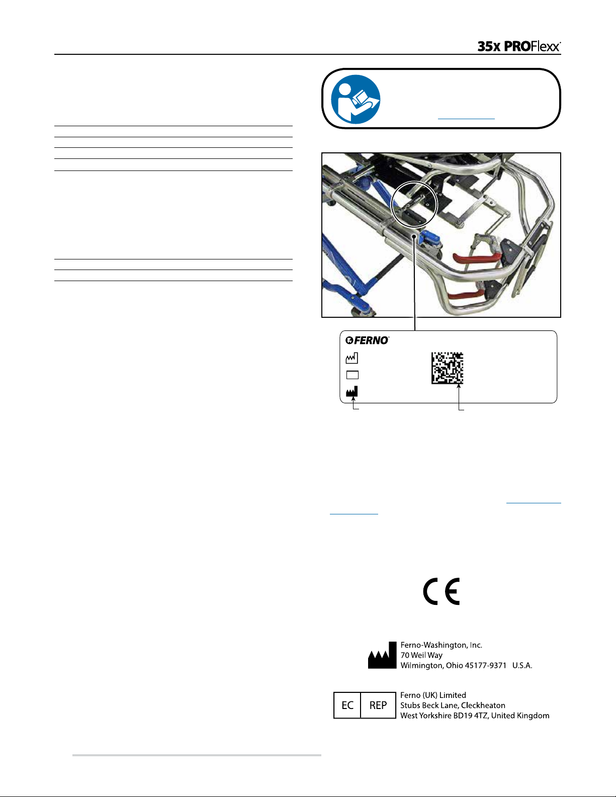
1.5 Safety and Instruction Labels _______________ 5
1.6 Symbol Glossary_________________________ 5
2 - Operator Skills and Training __________________ 6
2.1 Skills __________________________________ 6
2.2 Training________________________________ 6
2.3 Height and Strength Considerations __________ 6
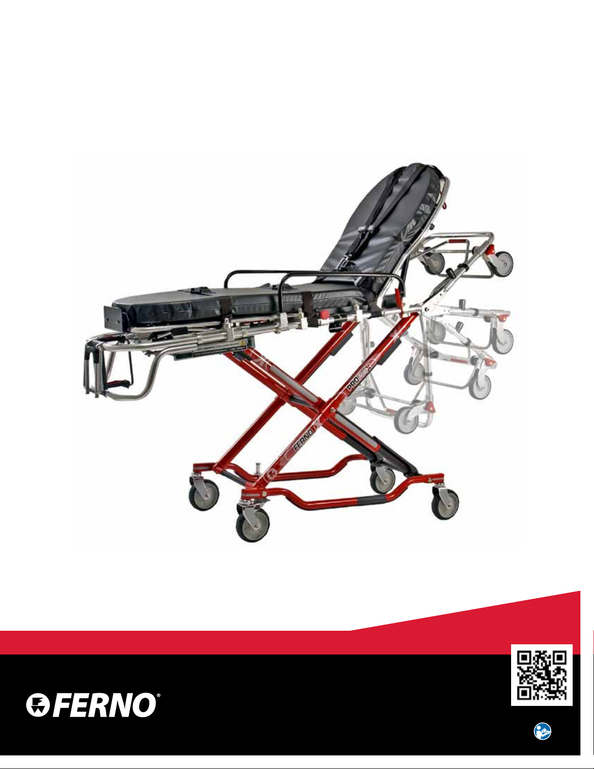
3 - About the Cot _______________________________ 7
3.1 Description _____________________________ 7
3.2 General Specications ____________________ 8
3.3 Cot Positions ____________________________ 8
4 - Setup and Installation ________________________ 9
4.1 Ambulance Requirements__________________ 9
4.2 Restraints, Mattress and Accessories _________ 9
4.3 Fastener Compatibility ____________________ 9
4.4 Install the Safety Hook ___________________ 10
5 - Cot Features _______________________________ 12
5.1 Control Handles ________________________ 12
5.2 Fastener Release Controls_________________ 13
5.3 Drop Frame ____________________________ 13
5.4 Backrest_______________________________ 14
5.5 Shock Frame ___________________________ 14
5.6 Lead Handle ___________________________ 14
5.7 Sidearms: Swing-Down (Standard) _________ 15
5.8 Sidearms: Universal (Optional) ____________ 15
5.9 Telescoping Side Lift Handles _____________ 16
5.10 Wheel Locks ___________________________ 16
5.11 Mattress_______________________________ 16
6 - Using the Cot ______________________________ 17
6.1 Before Placing the Cot in Service___________ 17
6.2 General Guidelines for Use________________ 17
6.3 Fully Engaging the Locking Mechanism _____ 17
6.4 Changing Cot Positions___________________ 18
6.5 Transferring the Patient___________________ 19
6.6 Rolling the Cot _________________________ 20
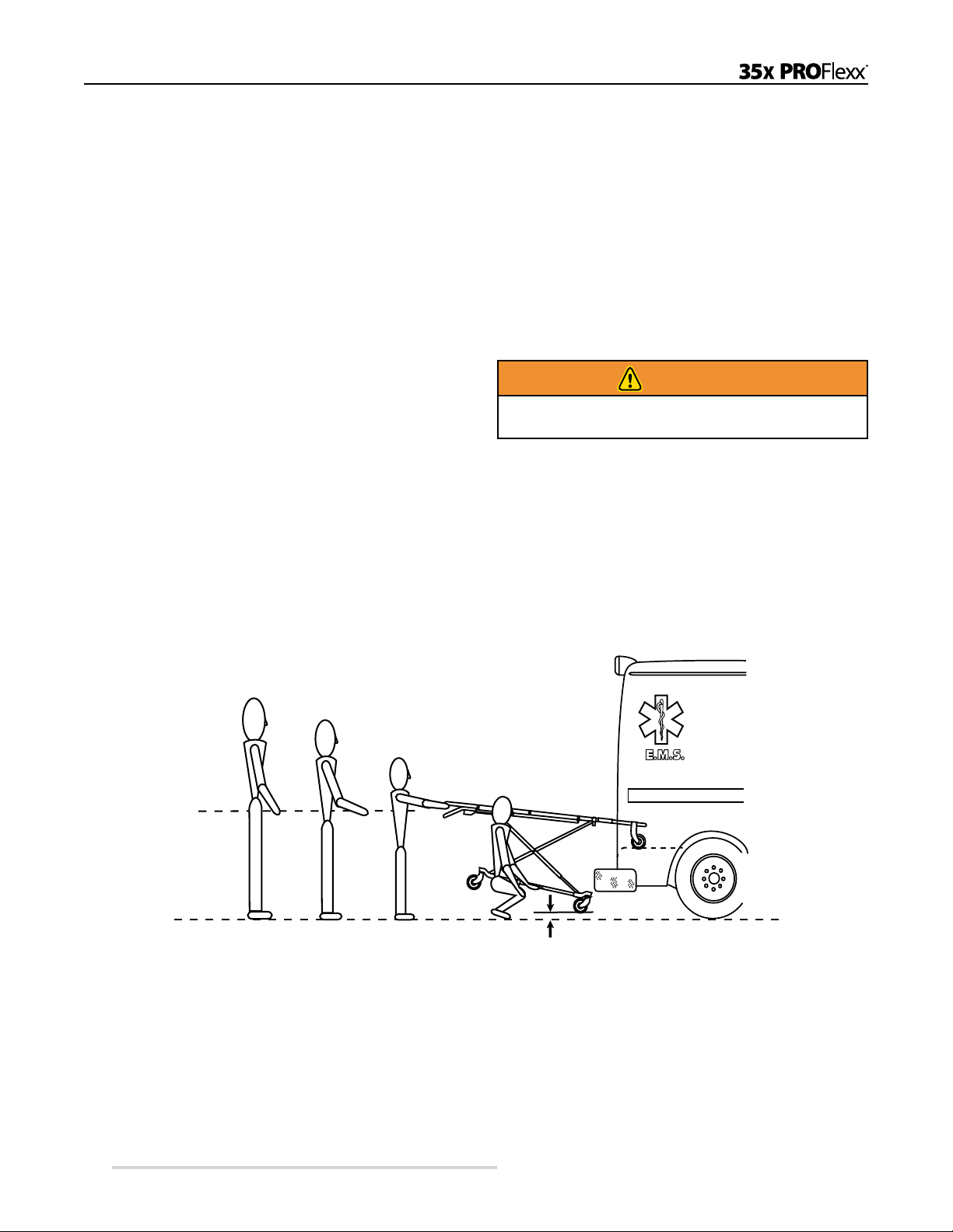
6.7 Preparing to Load the Cot_________________ 21
6.8 Loading the Cot_________________________ 22
6.9 Unloading the Cot_______________________ 23
6.10 One Operator, Empty Cot _________________ 24
6.11 Using Additional Help ___________________ 25
7 - Bariatric Transport _________________________ 26
7.1 Bariatric Transport Denition ______________ 26
7.2 Bariatric Transport Guidelines _____________ 26
7.3 Bariatric Transport: Transferring the Patient __ 27
7.4 Bariatric Transport: Rolling the Cot _________ 27
7.5 Bariatric Transport: Loading the Cot ________ 28
7.6 Bariatric Transport: Unloading the Cot_______ 28
8 - Maintenance _______________________________ 29
8.1 Maintenance Schedule ___________________ 29
8.2 Disinfecting and Cleaning the Restraints _____ 29
8.3 Disinfecting and Cleaning the Mattress ______ 29
8.4 Disinfecting the Cot _____________________ 29
8.5 Cleaning the Cot ________________________ 30
8.6 Waxing the Cot _________________________ 30
8.7 Inspecting the Cot _______________________ 30
8.8 Lubricating the Cot ______________________ 31
8.9 Accessing the 9th Bed Position_____________ 31
9 - Parts and Service ___________________________ 32
9.1 U.S.A. and Canada ______________________ 32
9.2 Worldwide_____________________________ 32
9.3 Parts List ______________________________ 32
9.4 Parts Diagrams _________________________ 33
10 - Accessories _______________________________ 34
Training Record ______________________________ 35
Maintenance Record___________________________ 35

4© Ferno-Washington, Inc 234-3346-04 April 2017
1 SAFETY INFORMATION
1.1 Warning
Warning notices indicate a potentially hazardous situation
which, if not avoided, could result in injury or death.
WARNING
Untrained operators can cause injury or be injured. Permit
only trained personnel to operate the cot.
Improper use of the cot can cause injury. Use the cot only
for the purpose described in this manual.
Attaching improper items to the cot can cause injury. Use
only Ferno-approved items on the cot.
Failure to use the safety hook can cause injury. Install and
use the safety hook as described in this manual.
Improper operation can cause injury. Operate the cot only
as described in this manual.
An unattended patient can be injured. Stay with the
patient at all times.
An unrestrained patient can fall o the cot and be injured.
Use restraints to secure the patient on the cot.
False locking can cause injury. After changing positions,
lift the cot until all the wheels are o the ground. This
allows the lock to engage if it has not already done so.
Rolling the cot sideways or in a loading position can cause
it cot to tip and injure the patient or operators. Roll the
cot only in a level (rolling) position and with the head-end
or foot-end rst.
Helpers can cause injury or be injured. Maintain control
of the cot, operate the controls, and direct all helpers.
Improper bariatric transport can cause injury to the
patient, operators and helpers. Follow local protocols and
the instructions in this manual.
Heavy loads can cause injury. Use as many additional
operators and helpers as needed to safely transport the
patient.
Using a raised position for bariatric transport can cause
injury and cot failure. Keep the cot folded when exceeding
the Standard Load Limit.
Improperly unloading a cot during bariatric transport
can cause injury. Station one operator or helper in the
ambulance to release the cot from the safety hook or
safety stop.
Improper maintenance can cause injury. Maintain the cot
only as described in this manual.
Improper parts and service can cause injury. Use only
Ferno parts and Ferno-approved service on the cot.
Modifying the cot can cause injury and damage. Use the
cot only as designed by Ferno.
1.2 Important
Important notices emphasize important usage or maintenance
information.
Important
1.3 Bloodborne Disease Notice
To reduce the risk of exposure to bloodborne diseases
such as HIV-1 and hepatitis when using the cot, follow the
disinfecting and cleaning instructions in this manual.
1.4 Cot and Fastener Compatibility
Combining different manufacturers’products into a “mixed-
component” cot/cot fastener system can increase the user’s
risk of injury and damage.
Ferno-Washington, Inc. strongly recommends that only
Ferno-manufactured cots be used in Ferno-manufactured cot
fasteners, and that only Ferno-manufactured cot fasteners be
used for securing Ferno-manufactured cots in ambulances.
ANY COMBINATION OF A FERNO COT OR COT
FASTENER WITH A NON-FERNO COT OR COT
FASTENER IS MISUSE OF THE FERNO PRODUCT.
Responsibility for the outcome of known, intentional misuse
rests squarely on the misuser.
Safety Information

5
© Ferno-Washington, Inc 234-3346-04 April 2017
1.5 Safety and Instruction Labels
Safety and instruction labels place important information from the users’
manual on the cot.
● The general information label shown at right is afxed to the foot-end
frame. It provides general safety, load limit, and use information.
● The hand-guard label shown below reminds the user not to remove the
hand guard.
Read and follow label instructions. Replace worn or damaged labels
immediately. New labels are available from EMSAR (page 32) or from
your distributor.
1.6 Symbol Glossary
The symbols dened below are used on the cot and in this users’ manual. Ferno uses symbols recognized by the International
Standards Organization (ISO), American National Standards Institute (ANSI) and the emergency medical services industry.
Safety Information
General Warning of
Potential Injury
Cot meets European
Union Standards
Unlocked Locked
Cot Operation Requires
Two Trained Operators
2
Do Not
Lubricate
Lubricate
Read the Users’
Manual
700 lb
318 kg
Standard Load Limit
Use Cot Normally
1100 lb
500 kg
Bariatric Load Limit
Use Cot in Folded
Position Only

6© Ferno-Washington, Inc 234-3346-04 April 2017
2 OPERATOR SKILLS AND TRAINING
2.1 Skills
Operators using the cot need:
● a working knowledge of emergency patient-handling
procedures.
● the ability to assist the patient.
WARNING
Untrained operators can cause injury or be injured.
Permit only trained personnel to operate the cot.
2.2 Training
Operator trainees need to:
● read and understand this manual.
● be trained on the use of the cot.
● practice with the cot before using it with a patient.
● record their training information. A sample training
record sheet is provided on page 35.
2.3 Height and Strength Considerations
When unloading the cot, the foot-end operator must lift
and hold the weight of the cot, patient and equipment high
enough for the wheels to remain off the ground until the
undercarriage legs completely unfold and lock into place.
Supporting this weight requires greater strength from short
operators than from tall operators because short operators
must raise their arms higher in relation to their shoulders.
Be aware that if the ambulance is parked on an uneven
surface, the foot-end operator (and any helpers) may need
to lift the cot higher than normal to allow the legs to unfold
completely and lock.
Bariatric transport requires special operating procedures.
See Bariatric Transport, pages 26-28.
Note: Use additional help as needed to lift the weight of the cot,
patient and equipment (see Using Additional Help, page 25).
Operator Skills and Training

7
© Ferno-Washington, Inc 234-3346-04 April 2017
3 ABOUT THE COT
3.1 Description
The Ferno®PROFlexx®Model 35X Series Cot (called the
cot in this manual) is an emergency patient-handling device
designed to transport a patient in a ground-based ambulance.
The cot is for professional use by a minimum of two trained
operators. It is designed for roll-in loading to help reduce
the risk of back injury to medical service personnel.
The cot is designed for use with Ferno®cot fasteners (not
included).
COT OPTIONS
● PROFlexx®35X: Standard cot for use with Ferno®
Model 175 (antler and rail) fastening system.
● PROFlexx® 35X-ST: Cot is compatible with Ferno®
Stat Trac®cot fastener system.
● Accessories: Your cot may have been shipped
with factory-installed accessories per your order;
accessories are also available separately.
INCLUDED WITH PURCHASE
● Mattress (1 of 4 styles. See “Customer Choice” Build
Options on this page).
● Set of 3 restraints
● Users’ manual
● Safety Hook (not required or included with 35X-ST)
U.S.A. NOTICE
The cot is for use with ambulances that meet the requirements
of the “Star of Life” certication via Federal Ambulance
Specication KKK-A-1822. For information, contact:
Federal Supply Services, Specications Section
Suite 8100
470 E. L’Enfant Plaza, SW
Washington, DC 20407
WARNING
Improper use of the cot can cause injury. Use the cot
only for the purpose described in this manual.
About the Cot
STANDARD FEATURES
All cots are built with the following features:
● Clear Anodized handling surfaces (helps keep hands
and clothing clean)
● High-visibility control handles (red)
● 9 Height positions
○3 loading positions for vehicle oors 28"-33"
● EZ-Pull control handles at cot foot end (control handle
may be activated before lifting weight of cot)
● Shock Frame (2-position)
● Drop Frame (5 positions with 4 locking positions)
● Backrest (pneumatic, innite-positioning 0°-65°)
● 6" Swivel Transport Wheels (4; 2 w/wheel locks)
● Telescoping Lift Handles (2)
● Restraints (set of 3)
● Head-end Leg Protectors
● Lower-Frame Scuff Strips
● Folding Lead Handle
“CUSTOMER CHOICE” BUILD OPTIONS
One each of the following options is standard equipment on
your cot:
● Color (your choice of 5 colors)
● Cot-Fastener Compatibility
○Ferno®Model 175 Antler-and-Rail
○Ferno®Model 185 Stat Trac®
● High-Reectivity Labels
○Standard high-reectivity labels
○Personalized high-reectivity labels
● Sidearms
○Ferno®Universal (swing- and fold-down) sidearms
○Ferno®swing-down sidearms
● Mattress Options*
○Mattress with locking hooks
○Mattress with locking hooks and pocket
○Mattress with locking hooks, pocket, transfer board
○Mattress with hook-and-loop fastener
* Mattresses are also available as accessories
and as replacement parts.

8© Ferno-Washington, Inc 234-3346-04 April 2017
3.2 General Specications
Height1
Bed Position 9 40 in./102 cm
Loading Position 3 35 in./89 cm
Bed Position 8 39 in./98 cm
Loading Position 2 31 in./79 cm
Bed Position 7 37 in./93 cm
Loading Position 1 27 in./69 cm
Bed Position 6 34 in./87 cm
Bed Position 5 31 in./79 cm
Bed Position 4 28 in./71 cm
Bed Position 3 24 in./62 cm
Bed Position 2 20 in./51 cm
Bed Position 1 (folded) 14 in./35 cm
Length
Maximum 79 in./201 cm
Minimum 64 in./162 cm
Width (Overall) 24 in./61 cm
Weight292 lb/42 kg
Weight (ST)2100 lb/45 kg
Strength to Weight Ratio37.6 SWR
Strength to Weight Ratio (ST)37.0 SWR
Load Limit 700 lb/317 kg
Bariatric Load Limit41,100 lb/500 kg
General specications are rounded to the nearest whole number.
Metric conversions are calculated before rounding the Imperial
measurements. For more information, contact Ferno Customer
Relations (page 2) or your Ferno distributor.
Ferno reserves the right to change specications without notice.
1Height measurements are as follows: Loading Position is the
distance from the ground to the bottom of the loading wheel. Bed
Position is the distance from the ground to the patient surface at the
telescoping handle.
2Weight is without mattress, restraints and optional features.
3Strength to Weight Ratio is the load limit of the cot divided by the
cot’s weight.
4Bariatric transport requires special operating procedures. See
pages 26-28.
3.3 Cot Positions
About the Cot
STANDARD LOAD LIMIT
ALL COT POSITIONS
700 lb
318 kg
BARIATRIC LOAD LIMIT
FOLDED POSITION ONLY
Follow bariatric transport procedures (pages
26-28) when working with loads in excess of
the Standard Load Limit. Inspect the cot if the
Standard Load Limit has been exceeded (see
Inspecting the Cot, page 30).
1100 lb
500 kg
FOLDED POSITION
Use the folded position to transfer the patient, to roll the cot
during bariatric transport, or to store the cot.
LOADING POSITIONS 3
The loading position is for use only when loading the cot
into, or unloading the cot from, an ambulance. Use the
lowest loading position that allows the cot to roll into your
ambulance.
Loading Position
Bed Position
ROLLING/TRANSFER POSITIONS 5
Use a level position to roll the cot and for transferring the
patient to or from the cot and an adjacent surface.
Bed Position
Important
Not all users require the highest (9th) Bed/Loading
Position. By default, this Bed Position is locked out
by a metal plate that limits the cot to Positions 1-8. If
your ambulance has a very high loading height that
requires the 9th Bed Position, see Accessing the 9th
Bed Position, page 31.

9
© Ferno-Washington, Inc 234-3346-04 April 2017
4 SETUP AND INSTALLATION
4.1 Ambulance Requirements
The ambulance bumper extension should not exceed 14
inches (35.5 cm). The patient compartment should have a
level oor large enough for the folded cot, and a Ferno®
cot fastener installed (not included). See Cot and Fastener
Compatibility, page 4.
Important
Loose items and debris on the patient compartment
oor can interfere with the operation of the cot with the
fastener. Keep the patient compartment oor clear.
Before placing the cot in service,
assign appropriate personnel to
install the mattress, restraints, and
any accessories shipped with the
cot. Keep restraint and accessory
users’ manuals with this manual for
future reference. For additional, free
manuals, contact Ferno Customer Relations (page 2).
For complete list of accessories, see Accessories, page 34.
WARNING
Attaching improper items to
the cot can cause injury. Use
only Ferno-approved items
on the cot.
4.3 Fastener Compatibility
Read the cot fastener users’ manual for instructions on using
the fastener (see Cot and Fastener Compatibility, page 4).
ANTLERANDRAIL FASTENERS
Model 35X series cots are compatible with all versions of
the Ferno®Model 175 antler and rail cot fasteners. The cot
fastener must be congured for use with the Ferno®Model
35 Series - see the fastener installation manual for details.
Using the Model 175 cot fastener requires the installation of
the safety hook (included).
Important
Stat Trac fasteners installed before June 1, 2000 required
only 16" (41 cm) of clearance from the ambulance wall
to the center of the Stat Trac.
The 6-inch wheels on PROFlexx® Series cots require the
fastener to be positioned at least 17" (43 cm) from the
wall to allow room for the wheels to swivel as the cot is
removed.
If you installed a Stat Trac at the old minimum, you must
reposition your Stat Trac to at least the new 17-inch
minimum. Contact Ferno Customer Relations (page 2)
for a revised Stat Trac installation manual.
Setup/Installation
4.2 Restraints, Mattress and Accessories
Figure 1 - Restraints (Set of 3)
Torso Restraint (1)
Guide Strap (1)
Two-Piece Restraint (2)
STAT TRAC FASTENERS
Model 35X-ST Series cots are compatible with all versions
of the Ferno®Model 185 Stat Trac®fastener. The center of
the fastener must be a minimum of 17" (43 cm) from the
ambulance wall. If the fastener was installed closer than this
minimum distance, it must be reinstalled further from the
wall to provide room for the cot wheels to swivel during
loading and unloading.
Important
A “sloped” (or low-prole) mounting block (shown
here) must be used when the antler portion of the cot
fastener is removable (installed with large turn-knobs
for easy removal).
If your removable fastener
does not already have this
mounting block, contact Ferno
Customer Relations, page 2.
This block is not used with fasteners permanently-mounted
to the oor with a large bolt.

10 © Ferno-Washington, Inc 234-3346-04 April 2017
WARNING
Failure to use the safety hook can cause injury.
Install and use the safety hook as described in this
manual.
Important
Beforeinstallingthe safetyhook, consultthe ambulance
manufacturer about possible interference with wiring
and other elements under the ambulance oor, and
about the ambulance warranty.
Figure 3 - Engaging the Safety Hook
Setup/Installation
4.4 Install the Safety Hook
Note: If your ambulance service uses only the Stat Trac®
Fastening System, skip the rest of Section 4.
The safety hook (Figure 2) provided with the cot is a
component of Ferno’s Model 175 Cot Fastening System,
and must be installed and used as described in this manual.
The safety hook catches the cot safety bar (Figure 3) to
ensure that the cot remains secured inside the ambulance
while the operators raise or lower the undercarriage during
loading or unloading.
Installing the safety hook requires the skills of a mechanic
familiar with ambulance construction.
Before installing the safety hook, consult the ambulance
manufacturer regarding:
● the location of wiring, oxygen or fuel lines, and other
elements under the ambulance oor.
● the ambulance warranty.
HARDWARE REQUIRED NOT SUPPLIED
2 1/4-20 Socket-head cap screws*
2 Flat washers
2 Lock washers
2 1/4-20 Nuts
*The socket-head cap screws must be long enough to pass
through the safety hook, patient compartment oor, both
washers, and still have at least two full threads extending
past the nut. The hardware should be of at least SAE Grade
5 with UNC-2 threading (or equivalent).
Figure 2 -Safety Hook
Front Edge
Hook

11
© Ferno-Washington, Inc 234-3346-04 April 2017
Figure 4 - Safety Hook Placement
Setup/Installation
INSTALLING THE SAFETY HOOK
1. Mark the position of the safety hook on the oor.
2. Drill holes for the socket-head cap screws and attach
the safety hook to the oor (Figure 5).
3. To test the hook, load and unload the cot. Verify that
there is no interference with folding or unfolding
the legs.
PROPER SAFETY HOOK PLACEMENT
Position the safety hook aligned with the center of the
fastener and as close to the rear of the ambulance as possible,
within the limits below:
● The bumper or extended folding bumper must not
exceed 14 inches (356 mm).
● Position the safety hook with the hook facing the front
of the ambulance.
● Position the safety hook at least 11 inches (279 mm)
from both sides of the door frame (Figure 4) so the
cot’s safety bar will engage the hook when the cot is
loaded or unloaded.
● Position the safety hook no more than
19-3/4 inches (451 mm) from the front edge of the hook
to the rear of the ambulance, including the bumper and
folding bumper step in the extended (open) position.
Important
If the safety hook is installed too far inside the ambulance,
you will not be able to properly fold or unfold the cot
undercarriage when it is secured by the hook. Measure
and install the safety hook as instructed in this manual.
11" Min.
11" Min.
19-7/8" Max.
Door Frame Extended
Bumper Step
Figure 5 - Installing the Safety Hook
Socket-Head
Cap Screw
Nut
Lock Washer
Flat Washer
Front Edge
Hook
Ambulance Rear Ambulance Front

12 © Ferno-Washington, Inc 234-3346-04 April 2017
5 COT FEATURES
5.1 Control Handles
● Purpose: An operator uses one of the undercarriage
control handles to unlock the locking mechanism that
allows the cot to be raised and lowered.
● Location: There are three control handles: an upper and a
lower handle at the cot foot end, and a side control handle
at the patient’s right side (Figures 6 and 7).
○To lift the cot evenly, the two trained operators must
stand opposite one another. If using the upper or
lower foot-end control handle, position the assisting
operator at the cot head end. If using the side control
handle, position the assisting operator at the opposite
side of the cot.
● Use: Any one of the handles may be used to disengage
the undercarriage lock.
○Use the control handle that is best for the lifting
situation. For example, the lower control handle
gives a short operator better leverage for lifting.
UNDERSTANDING HOW THE
FOOTEND CONTROL HANDLES FUNCTION
Two styles of foot-end control handles have been produced.
Practice with your cot before placing it in service so you will
understand how your cot operates. The two styles require
different procedures for using the cot.
● THE EZ-PULL STYLE control handle (serial numbers
09N-122459 and higher) requires less force to pull;
also, the control handle may be pulled rst, before the
operators raise or lower the cot.
● THE LIFT-FIRST STYLE control handle (unmodied
cots with serial numbers below 09N-122459) requires the
operators to lift the weight of the cot and patient off
the locking mechanism BEFORE pulling the control
handle. An update kit is available to change from the Lift-
First Style to the EZ-Pull Style handle.
Note:The side lifting handle is a Lift-First style handle.
Using the Features
Figure 7 - Side
Control Handle
Side
Control
Handle
Important
Two styles of foot-end control handle have been produced.
Understand how your cot functions and practice using the
cot without a patient before placing the cot in service.
Important
Cots with serial numbers below 09N-122459 may be
updated to the EZ-Pull style. Do not assume which
style of control handles a cot is equipped with. Practice
with the cot before using it in service.
Using the EZ-Pull Handle
1. Pull the control handle rst, before lifting the cot. This
allows you to grasp the cot with both hands and lift
evenly, without having to open your palm to operate
the handle after you assume the load.
2. In a motion coordinated with the head-end operator
and any helpers, assume the load by raising the cot
to take the weight off the locking mechanism.
3. Once the operators have assumed the load, the
mechanism will automatically disengage and the
cot can be raised or lowered to the desired height.
4. Release the handle when the cot is near the desired
height, then raise or lower the cot until the lock engages.
Before relaxing your grip on the cot main frame,
verify that the cot has locked at the new position.
Using the Lift-First Handle
1. In a movement coordinated with the head-end
operator and any helpers, lift the cot to take the
weight off the locking mechanism.
2. Open your left hand and pull the control handle to
unlock the cot’s locking mechanism.
3. Raise or lower the cot to the desired height.
4. Release the handle when the cot is near the desired
height, then raise or lower the cot until the lock engages.
Before relaxing your grip on the cot main frame,
verify that the cot has locked at the new position.
Figure 6 - Control Handle Versions
EZ-Pull Style
(Open Handle)
Lift-First Style
(Closed Handle)

13
© Ferno-Washington, Inc 234-3346-04 April 2017
Using the Features
5.2 Fastener Release Controls
● Purpose: The fastener release control lever (Model
35X) or fastener release control handle (Model 35X-
ST) allows the cot to be released from the cot fastener
during unloading the cot from an ambulance.
● Location: The lever or handle is located near the cot’s
loading wheels.
● Use: To release the cot from the cot fastener:
○35X: Release the cot from the safety hook by
turning the lever counter-clockwise (Figure 8).
○35X-ST: Release the cot from the safety stop by
squeezing the handle (Figure 9).
5.3 Drop Frame
● Purpose: The 5-position drop frame has many uses
(Figure 10).
○+2 (locked): The +2 position shortens the cot for
use when space is limited. This position is also used
to push the cot when it is being used as a bariatric
sled (See Rolling the Cot as a Sled, page 21 and
Bariatric Transport, pages 26-28).
○+1 (locked): The +1 position provides a good
ergonomic lifting angle for raising or lowering the
cot when the cot is at a low level.
○extended (locked): the extended position is
used by an operator for raising or lowering the
cot. This position is also used for loading the
cot into an ambulance or unloading it from an
ambulance. A safety bar (Model 35X) or head-end
loading post (Model 35X-ST) attached to the drop
frame secures the cot to a safety hook or safety
stop inside the ambulance during the loading or
unloading process.
○-1 (locked): The -1 position provides a good
ergonomic lifting angle for raising or lowering the
cot when the cot is at a high level.
○-2 (unlocked): The -2 position is used to shorten
the cot when space is limited. The frame is
unlocked and is not usable for lifting when in this
position.
● Use: Squeeze the release bar (Figure 11) to unlock the
drop frame, then raise or lower the drop frame to the new
position. Let go of the release bar at the new position.
○Raise the drop frame to the extended, +1 or +2
position before folding the cot.
Important
Extend or raise the drop frame before folding the
cot. Folding the cot with the drop frame in a lowered
position can damage the drop frame if it strikes the cot
undercarriage, oor, or ground.
Figure 11 - Drop Frame Release Bar
Figure 10 - Drop Frame Positions
+2
+1
-2
-1
Extended
Figure 8 - 35X Lever Figure 9 - 35X-ST Handle

14 © Ferno-Washington, Inc 234-3346-04 April 2017
5.4 Backrest
● Purpose: The backrest allows the operator to elevate the
patient’s torso for patient comfort or medical necessity.
● Before Use:
○Loosen or unbuckle the torso restraint.
○Support the weight of the backrest and patient.
● Use: Press the red control handle toward the backrest
frame to unlock the backrest (Figure 12), then raise or
lower the backrest to the desired position. Release the
control handle to lock the backrest at the new position.
○The gas spring is under pressure to ease raising
and lowering. When a heavy patient is on the
cot, support the patient’s weight before adjusting
the backrest. When a light patient is on the cot,
control the upward movement of the backrest so
it does not move too quickly.
○The backrest can be adjusted between 0° and 65°.
● After Use: Buckle and/or adjust the torso restraint.
Using the Features
Figure 12 - Using the Backrest
5.5 Shock Frame
● Purpose: The shock frame allows the operator to elevate
the patient’s legs to treat shock or for patient comfort.
● Use:
○Before use, loosen or unbuckle the leg restraint.
○To raise, stand at the foot end of the cot. Use both
hands to lift the shock frame until it locks in the
raised position.
○To lower, stand at the foot end of the cot. Lift the
shock frame a little to support the weight, then
press the shock frame control levers (Figure 13)
and lower the shock frame.
○After use, buckle and/or adjust the leg restraint. Figure 13 - Lowering the Shock Frame
Control Lever (2)
5.6 Lead Handle
● Purpose: The lead handle allows the foot-end operator
to pull the cot when it is in a rolling position.
● Use: Unfold the lead handle for use (Figure 14); fold
it for storage.
○Do not allow the lead handle to hang unfolded.
○Use the lead handle only when the cot is on a
smooth, level surface. When the cot is on an
incline or rough terrain, grasp the main frame of
the cot with both hands.
Figure 14 - Using the Lead Handle

15
© Ferno-Washington, Inc 234-3346-04 April 2017
5.7 Sidearms: Swing-Down (Standard)
● Purpose: Sidearms provide patient security and
comfort. Keep the sidearms raised except during patient
transfer. The sidearms feature an intermediate stop that
allows a patient’s arm to be placed on the sidearm for
treatment, starting of intravenous (IV) uids, etc.
● Use:
○To lower, squeeze the sidearm release handle
(Figure 15) and lower the sidearm. To stop at the
intermediate position, let go of the release handle
before the sidearm reaches the 90° point. To fully
lower the sidearm, continue holding the release
handle until the sidearm has passed the 90° point.
○To raise, lift the sidearm until it locks. You do not
need to use the release handle.
5.8 Sidearms: Universal (Optional)
● Purpose: Sidearms provide patient security and
comfort. Keep the sidearms raised except during
patient transfer. The sidearms feature an intermediate
stop that allows a patient’s arm to be placed on the
sidearm for treatment, starting of intravenous (IV)
uids, etc.
○The universal sidearms fold along the cot main
frame or swing down like a standard sidearm.
● Use:
○To fold: Press the release lever (Figure 16) and fold
the sidearm at along the cot main frame.
○To lower: Press the release lever, pull the sidearm
slightly toward the foot end of the cot to free it
from the lock, then swing the sidearm down below
the cot main frame.
○To use the intermediate position: Press the release
lever and begin folding and lowering the sidearm,
then slide the sidearm toward the head end of the
cot to lock it before lowering to the 90° point.
○To raise: Swing and/or lift the sidearm toward the
head end of the cot until it locks.
Using the Features
Figure 15 - Lowering the Sidearm
Important
Do not use the sidearms to lift the cot. Sidearms are
not designed for lifting. Lift the cot only by grasping
the main frame, or main frame and side lift handles.
Important
Sidearms are designed to support light objects. Do not
place objects weighing more than 10 pounds (4.5 kg)
on the sidearms.
Important
Do not use the sidearms to lift the cot. Sidearms are
not designed for lifting. Lift the cot only by grasping
the main frame, or main frame and side lift handles.
Important
Sidearms are designed to support light objects. Do not
place objects weighing more than 10 pounds (4.5 kg)
on the sidearms.
Figure 16 - Using the Universal Sidearm
Release Lever

16 © Ferno-Washington, Inc 234-3346-04 April 2017
5.11 Mattress
● Purpose: The mattress provides comfort for the patient.
● Mattress Options (4): Mattress with 5 plastic hooks;
mattress with hooks and transfer-board pocket; mattress
with hooks, transfer-board pocket, and transfer board;
mattress with hook-and-loop fastening strips.
● Use: The bottom of the mattress has either 5 plastic
hooks or hook-and-loop fastening strips. The hooks or
hook-and-loop strips help hold the mattress in place
when transferring a patient onto or off from the cot.
○To Attach: Raise the backrest and/or shock frame
as needed and either feed each hook through a
hole in the bed surface (Figure 19) OR press the
hook-and-loop surfaces together.
○To remove: Slide one hand under the mattress
and apply upward pressure, then remove each
hook from the bed surface with your other hand
OR separate the hook-and-loop fastening strips.
5.9 Telescoping Side Lift Handles
● Purpose: The telescoping side lift handles can be
used as extra lifting or grasping points by operators or
additional helpers.
● Location: The lift handles are located near the center
of the cot.
● Use: Pull to extend the lift handle, push to retract.
○Retract the lift handles when using the side control
handle to raise or lower the cot.
○Figure 17 shows one option for hand placement
for lifting the cot. Alternately, grasp the lift handle
with both hands.
○Balance the cot by placing one operator or helper
on each side of the cot; lift together, using both
lift handles.
Figure 17 - Hand
Placement
for Using
the Lift Handles
5.10 Wheel Locks
● Purpose: The wheel locks help keep the cot stationary
during patient transfer and certain medical procedures.
When engaged, the wheel lock stops wheel rotation and
caster swiveling.
● Location: Wheel locks are located at opposite corners
of the cot where they are accessible to the operator’s
right foot.
● Use: Press the lock lever to engage; tap the top part of
the lock lever to disengage (Figure 18).
○Wheel locks are not brakes. Stay with the cot and
maintain control of it at all times. Do not leave the
cot or patient unattended.
Figure 18 -
Wheel Lock
Figure 19 - Mattress Hooks Through Bed Surface
Using the Features

17
© Ferno-Washington, Inc 234-3346-04 April 2017
6 USING THE COT
6.1 Before Placing the Cot in Service
● Personnel who will work with the cot need to read this manual.
● Set up the cot, following the instructions in Setup and Installation,
pages 9-11.
● Conrm that the cot operates properly. See Inspecting the Cot, page 30.
● The vehicle must have a Ferno cot-fastening system installed.
WARNING
Improper operation can cause
injury. Operate the cot only as
described in this manual.
WARNING
An unattended patient can be
injured. Stay with the patient
at all times.
6.2 General Guidelines for Use
● Medical advice is beyond the parameters of
this manual.
● It is the users’ responsibility to ensure safe
practices for the patient and themselves.
● A minimum of two trained operators is
required.
● Follow standard emergency patient-handling
procedures when operating the cot.
● Stay with the patient at all times.
● Always use patient restraints to secure the
patient on the cot.
● Operators work together and maintain
control of the cot at all times.
● Operators communicate with one another
and use coordinated movements to operate
the cot.
● Lift only the weight you can safely handle.
Use additional help when working with heavy loads (patient and equipment). For
placement of helpers, see Using Additional Help, page 25.
● Keep the cot folded when the load exceeds the Standard Load Limit (see Bariatric
Transport, pages 26-28). Inspect the cot if the Standard Load Limit has been
exceeded (see Inspecting the Cot, page 30).
WARNING
An unrestrained patient can
fall o the cot and be injured.
Use restraints to secure the
patient on the cot.
WARNING
False locking can cause injury.
After changing positions, lift
the cot until all the wheels
are o the ground. This allows
the lock to engage if it has not
already done so.
6.3 Fully Engaging the Locking Mechanism
False locking is a condition in which the locking mechanism does not fully engage when
a control handle is released. This can occur after changing cot positions if the locking pin
rests exactly on the tip of a ratchet bar tooth, and can allow the cot to lower to the next
locking position when moved.
To ensure the locking mechanism fully engages after changing positions, lift the cot
until all the wheels are off the ground. This allows the lock to fully engage if it has not
already done so.
Using the Cot
STANDARD LOAD LIMIT
ALL COT POSITIONS
700 lb
318 kg
BARIATRIC LOAD LIMIT
FOLDED POSITION ONLY
1100 lb
500 kg
Two Trained
Operators Required
2
Read the Users’
Manual

18 © Ferno-Washington, Inc 234-3346-04 April 2017
6.4 Changing Cot Positions
Changing cot positions with a patient on the cot requires a
minimum of two trained operators working together.
PREPARING TO RAISE OR LOWER THE COT
Operators do the following:
● Stand at opposite ends or sides of the cot (Figures 20-22).
● Select the lifting position that provides the best
leverage (Figures 20 or 21).
● Use an underhand grip to grasp the cot main frame.
● Control Operator only: Position your hand to use the
control handle.
● Choose the appropriate set of steps below.
Important
Operators should expect and be prepared to control
the normal downward movement of the cot that occurs
when a control handle is squeezed.
Using the Cot
Figure 20- Upper Lifting Positions
Figure 21 - Lower Lifting Positions
Figure 22 -
Changing
Positions from
the Side
Important
• With the EZ-Pull Handle, you may pull the control
handle rst, then lift the cot (See page 12).
• With the Lift-First Handle, you must lift the cot before
you pull the control handle (See page 12).
EZPULLSTYLE CONTROL HANDLE
1. Control Operator: Pull the control handle.
2. Both Operators: Lift the cot high enough for the
weight to be removed from the locking mechanism so
the locking mechanism will disengage.
3. Both Operators: Both operators raise or lower the cot.
4. Control Operator: Release the control handle when
the cot is near the desired height.
5. Both Operators: Together, lift the cot until all four
transport wheels are off the ground. This ensures the
undercarriage lock engages if it has not already done so.
6. Both Operators: Set the cot onto the oor or ground.
Do not release your grasp until your are sure the
undercarriage is locked at the new position.
LIFTFIRSTSTYLE CONTROL HANDLE
1. Both Operators: Lift the cot slightly to take the
weight off the locking mechanism.
2. Both Operators: As the control operator squeezes and
holds the control handle, both operators raise or lower
the cot. If the control handle is difcult to squeeze,
both operators lift the cot a little higher to free the
locking mechanism.
3. Control Operator: Release the control handle when
the cot is near the desired height.
4. Both Operators: Together, lift the cot until all four
transport wheels are off the ground. This ensures the
undercarriage lock engages if it has not already done so.
5. Both Operators: Set the cot onto the oor or ground.
Do not release your grasp until your are sure the
undercarriage is locked at the new position.

19
© Ferno-Washington, Inc 234-3346-04 April 2017
HOW TO RECOVER FROM
IMPROPERLY FOLDING THE COT
If you attempt to fold the cot with the drop frame locked in
the lower lifting (-1) position, the drop frame mechanism
will bind and cause the cot not to sit level.
If this occurs, do not release the drop frame hinges; you
could jar the patient and/or damage the hinge mechanism.
To recover, both operators raise the cot into a higher
position. Adjust the drop frame to the extended position
and then fold the cot.
Important
Do not fold the cot with the drop frame locked in
the lower lifting position. Place the drop frame in the
extended position or higher before folding the cot. Use
two-stage lowering if needed (see above).
Using the Cot
Raising or Lowering
the Cot in Two Stages
To maintain proper lifting techniques, the operators may
choose to adjust the cot height in two stages (Figure 23).
To do this:
1. Use one set of lifting positions to raise or lower the
cot partway.
2. Stop at a comfortable position and verify that the
undercarriage is locked.
3. Adjust your hands to new lifting positions:
○Assisting Operator: Raise or lower the drop
frame to a different locked position.
○Control Operator: Move your hands from
the main frame to the lower lift frame or
vice-versa.
4. Raise or lower the cot to the desired nishing
position.
Figure 23 - Two-Stage Position Changes
6.5 Transferring the Patient
To transfer a patient onto the cot:
1. Unfasten the restraints and arrange the straps so they will
not interfere with transferring the patient onto the cot.
2. Place the cot beside the patient and adjust it to the
patient’s level.
3. Engage the wheel locks, lower or fold the sidearms,
and retract the side lift handles.
4. Transfer the patient onto the cot using approved EMS
procedures and your local protocols.
5. Raise the sidearms. Adjust the backrest and shock
frame as needed.
6. Fasten and adjust the patient restraints (Figure 24).
7. Release the wheel locks.
8. Before moving the cot or changing its position, verify
that sheets and other articles are positioned where they
will not interfere with cot operation.
Figure 24 - Securing the Patient
Important
Sheets or other articles that are placed, or nd their way,
beneath the metal bed of the cot can become caught in
the ratchet mechanism and cause it to malfunction.Take
care to tuck sheets between the mattress and the metal
bed of the cot. Keep other articles above the mattress.

20 © Ferno-Washington, Inc 234-3346-04 April 2017
Using the Cot
6.6 Rolling the Cot
GENERAL GUIDELINES
● Rolling the cot with a patient on the cot requires aminimum of
two trained operators working together and maintaining
control of the cot at all times.
● Rolling the cot in a loading position can cause the cot to tip.
Always use a rolling position to roll the cot (see Cot Positions,
page 8).
● Roll the cot on smooth, unobstructed surfaces whenever
possible.
● To cross a low obstacle such as a door sill, lift the cot slightly
to take the weight off the wheels so the wheels roll smoothly
over the obstacle.
● Lift and carry the cot over a high obstacle such as a curb. Do
not apply downward force on one end of the cot in order to
raise the other end of the cot over the obstacle.
● Do not roll the cot sideways. Rolling a cot sideways can
increase the chance for the cot to tip and injure the patient
and/or operators.
● Use additional help as needed to safely control the weight of
the patient and cot (see Using Additional Help, page 25).
● When using additional help, trained operators stand at the
head and foot ends of the cot and work the controls. Helpers
can extend the side lifting handles or grasp the main frame,
and assist the trained operators.
● When rolling over rough terrain, the operators (and helpers)
should grasp the cot with both hands. Side operators or
helpers place both hands on the main frame or lifting handles,
or place one hand on each.
● Side helpers may need to walk sideways under some
circumstances. Follow local protocols.
● If the load (patient plus equipment) exceeds the cot’s Standard
Load Limit, use bariatric transport techniques. see Bariatric
Transport, pages 26-28.
WARNING
Rolling the cot sideways or in a loading position
can cause it cot to tip and injure the patient or
operators. Roll the cot only in a level (rolling)
position and with the head-end or foot-end rst.
Important
Roll the cot downhill foot-end rst. If it is not
medically appropriate to do this, roll the cot
head-end rst, but do the following:
To maintain cot balance while rolling the cot
downhill head-end rst, the Assisting Operator
must exert upward force on the drop frame.
ROLLING THE COT
1. Securely fasten the restraints around the patient.
2. Both Operators: Place the cot in a rolling position. See Cot
Positions, page 8.
3. Control Operator: Position yourself at the foot end of the
cot, grasp the main frame, and pull the cot forward. Or, if
rolling the cot on a smooth, at surface, unfold the lead
handle and pull the transporter (Figure 25).
4. Assisting Operator: Position yourself at either the head-end
of the cot (grasping the drop frame) or at the side of the cot
near the patient’s torso (grasping the main frame, Figure 25).
Attend the patient and assist in rolling and steering the cot.
Figure 25 - Rolling the Cot
Assisting
Operator
Control
Operator
Table of contents