Festo OVEM User manual

en Operating
instructions
8068021
1702e
[8068023]
Vacuum generator
OVEM

OVEM
2Festo – OVEM – 1702e
Original instructions
OVEM-DE
Identification of hazards and instructions on how to prevent them:
Warning
Hazards that can cause death or serious injuries
Other symbols:
Note
Material damage or loss of function
Recommendations, tips, references to other documentation
Text designations:
Activities that may be carried out in any order
1. Activities that should be carried out in the order stated
– General lists
èResult of an action/References to more detailed information

OVEM
Festo – OVEM – 1702e English 3
1 Product description 5.......................................................
1.1 Structure 5................................................................
1.2 Characteristics 6...........................................................
2 Security 7.................................................................
2.1 Use for intended purpose 7...................................................
2.2 General safety information 7..................................................
2.3 Range of applications and certifications 8.......................................
3 Function and application 9...................................................
3.1 Function overview 9.........................................................
3.2 Switching functions 10........................................................
3.3 Valve control 11.............................................................
3.4 Air-saving function 13........................................................
3.5 Optimisation of the transport time 14............................................
3.6 Monitoring and diagnostics 14.................................................
3.7 Measured variables 15........................................................
3.8 Teach function (Teach-In) 16...................................................
4 Installation 17..............................................................
4.1 Mechanical 17..............................................................
4.2 Pneumatic 19...............................................................
4.3 Electric 20..................................................................
5 Commissioning 23...........................................................
5.1 Commissioning vacuum suction nozzle 23........................................
5.2 Set the intensity of the ejector pulse 24..........................................
6 Operation 25...............................................................
6.1 Setting the ejector pulse duration 25............................................
6.2 Configure the switching outputs 26..............................................
6.2.1 Display switching output settings 26....................................
6.2.2 Setting the switching characteristics of a switching output 26................
6.2.3 Set diagnostic message channel 27.....................................
6.2.4 Teaching of switching points 28........................................
6.2.5 Deleting the minimum or maximum pressure value 28......................

OVEM
4Festo – OVEM – 1702e English
6.3 Configuring the evacuation and air supply times 29.................................
6.3.1 Setting the limit values for the evacuation and air supply times 29.............
6.3.2 Teaching the evacuation and air supply time 29............................
6.3.3 Displaying the evacuation and air supply times 30.........................
6.3.4 Deleting the evacuation and air supply times 30...........................
6.4 Operating manual override 31..................................................
6.4.1 Mechanical manual override 31........................................
6.4.2 Electrical manual override 31..........................................
6.5 Activating security code 32....................................................
6.6 Switching the air saving function on or off 32......................................
6.7 Restore factory settings 33....................................................
7 Error messages and fault clearance 34..........................................
7.1 Diagnostic levels 34..........................................................
7.2 Error messages and error codes 35..............................................
7.3 Malfunctions 37.............................................................
8 Disassembly 38.............................................................
9 Maintenance and care 38.....................................................
10 Technical data 39............................................................
11 Appendix 41................................................................
11.1 Graphic display and LCD displays 41.............................................
11.2 Operating statuses and menu structure 45........................................
11.2.1 Meaning of symbols for representing the menu structure 45.................
11.2.2 RUN mode 45......................................................
11.2.3 SHOW mode 46.....................................................
11.2.4 EDIT mode 47......................................................
11.2.5 Teach mode 48.....................................................

OVEM
Festo – OVEM – 1702e English 5
1 Product description
1.1 Structure
1234
aJ
aA
aB
8
9
56
7
1Ejector pulse solenoid valve (Eject)
2Vacuum solenoid valve
3Mechanical manual override of the solenoid
valves
4Supply port (1)
5Exhaust port / silencer (3)
6Vacuum connection (2)
7Housing with mounting holes
8Slide for changing the filter element
9Filter housing with inspection window
aJ Flow control screw for adjusting the ejector
pulse
aA Vacuum sensor with LCD display and
operating keys èFig. 13
aB electrical connection
Fig. 1 Control sections and connections

OVEM
6Festo – OVEM – 1702e English
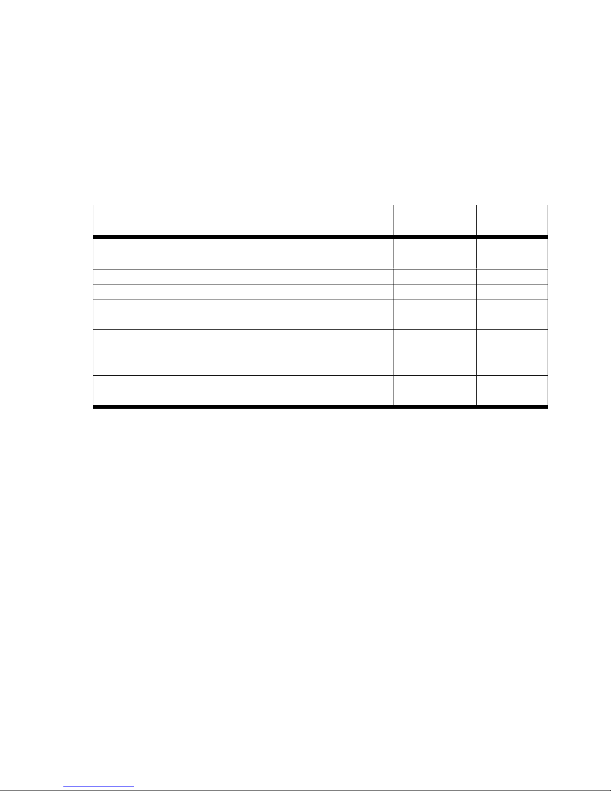
1.2 Characteristics
Characteristic Code Meaning
Vacuum suction nozzle OVEM Vacuum suction nozzle with vacuum solenoid valve ON/OFF
and electric manual override
Nominal width of laval
nozzle
-05 0.45 mm
-07 0.7 mm
-10 0.95 mm
-14 1.4 mm
-20 2.0 mm
Vacuum type -H high vacuum
-L high suction volume
Housing size / width -B 20 mm wide, ISO standard
-BN 20 mm wide, NPT
Pneumatic ports -QS all ports with QS push-in fittings (-B-QS)
all ports with QS push-in fittings inch (-BN-QS)
-QO Supply / vacuum port with QS push-in fittings, exhaust port
with open silencer (-B-QO)
Supply / vacuum port with QS push-in fittings inch, exhaust
port with open silencer (-BN-QO)
-GN all ports with female G thread (-B-GN)
all ports with female NPT thread (-BN-GN)
-GO Supply / vacuum port with female G threads, exhaust port
with open silencer (-B-GO)
Supply / vacuum port with female NPT threads, exhaust port
with open silencer (-BN-GO)
-PL prepared for manifold rail, vacuum and exhaust port with QS
push-in fittings (-B-PL)
prepared for manifold rail, vacuum and exhaust port with QS
push-in fittings inch (-B-PL)
-PO prepared for manifold rail, vacuum port with QS push-in
fittings, exhaust port with open silencer (-B-PO)
prepared for manifold rail, vacuum port with QS push-in
fittings inch, exhaust port with open silencer (-BN-PO)
Normal position of the va
cuum generator
-ON NO, normally open (vacuum generation)
-OE NO, normally open (vacuum generation) with ejector pulse
-CN NC, normally closed (no vacuum generation)
-CE NC, normally closed (no vacuum generation) with ejector pulse
Electrical connection -N Plug M12 (5-pin)

OVEM
Festo – OVEM – 1702e English 7
Characteristic MeaningCode
Vacuum sensor -1PD 1 switching output PNP, 2 switching input PNP, with display
-2P 2 switching outputs PNP
-2N 2 switching outputs NPN
-PU 1 switching output PNP, 1 analogue output 0 … 10 V
-PI 1 switching output PNP, 1 analogue output 4 … 20 mA
-NU 1 switching output NPN, 1 analogue output 0 … 10 V
-NI 1 switching output NPN, 1 analogue output 4 … 20 mA
Alternative vacuum display -bar (-B), InHg (-BN)
-B Bar
-W InH2O
-H InHg
Tab. 1 Overview of variants
2 Security
2.1 Use for intended purpose
The vacuum generator type OVEM is designed for generating a vacuum.
2.2 General safety information
– The product may only be used in its original status without unauthorised modifications.
– Only use the product if it is in an excellent technical status.
– Use the product only inside buildings.
– Take into consideration the ambient conditions at the location of use.
– The product is intended for use in industrial environments. The product can generate high frequency
interference, which may make it necessary to implement interference suppression measures in
residential areas.
– Observe the specifications on the product labelling.
– Comply with all applicable national and international regulations.
– Observe the local specifications for environmentally friendly disposal.

OVEM
8Festo – OVEM – 1702e English
2.3 Range of applications and certifications
Note
CE declaration of conformity and certificatesèwww.festo.com/sp
In connection with the UL marking on the product, the information of this section is also applicable for
compliance with the certification conditions of Underwriters Laboratories Inc. (UL) for the U.S.A. and
Canada.
UL approval information
Product category code QUYX (USA)
QUYX7 (Canada)
File number E322346
Considered standards UL 61010-1
C22.2 No.61010-1
UL mark
Tab. 2 UL approval information
Only for connection to an NEC/CEC Class 2 supply.
Unit shall be supplied by a power source which complies with the requirements of a limited-energy
circuit in accordance with IEC/EN/UL/CSA 61010-1 or a Limited Power Source (LPS) in accordance with
IEC/EN/UL/CSA 60950-1 or IEC/EN/UL/CSA 62368-1 or a Class 2 circuit in accordance with NEC or
CEC.

OVEM
Festo – OVEM – 1702e English 9
3 Function and application
3.1 Function overview
The OVEM is a vacuum suction nozzle with digital transmission of setpoint and actual value as well as
diagnostics and parameterisation options. Configuration is carried out via the operating keys. The dia
gnostic messages are shown in the display.
Function OVEM-...-2P/2N
/PU/PI/NU/NI
OVEM-...-1PD
Control of the compressed air supply with 2 valve functions
èChapter 3.3
x x
Air-saving function è Chapter 3.4 x x
Electrical and mechanical manual override èChapter6.4 x x
Monitoring of the vacuum build-up through integrated pressure
sensor and advanced monitoring functions èChapter 3.6
x x
Auto-Drop Function:
generation of an automatic eject pulse for accelerated vacuum
purging and safe set-down èChapter3.3
x -
Generation of an eject pulse via a control signal at the
digital switching input (ejection) DI2
- x
Tab. 3 Function overview

OVEM
10 Festo – OVEM – 1702e English
3.2 Switching functions
The switching outputs can be configured via the switching functions.
The switching logic of the switching outputs can be configured as normally open (NO) or normally
closed (NC).
The switching mode of the switching outputs can be determined as threshold value or window compar
ator.
With active air-saving function, the switching mode is determined as the threshold value
comparator by switching output A.
Threshold value comparator Normally open (NO) Normally closed (NC)
Switching function
– 1 Switchpoint (SP1)
Teach mode1):
– 2 Teach-in points (TP1, TP2)
– SP1 = ½ (TP1+TP2)
p
1
0
HY
OUT
SP1
TP1 TP2
p
1
0
SP1
HY
OUT
TP1 TP2
1) TP1 = minimum pressure value, TP2= maximum pressure value, independent of the Teach sequence
Tab. 4 Threshold value comparator: setting of switchpoint SP1 and hysteresis HY
Window comparator Normally open (NO) Normally closed (NC)
Switching function:
– 2 switchpoints
(SP1, SP2)
Teach mode1):
– 2 Teach-in points (TP1, TP2) TP1=SP1
HY HY
p
1
0
OUT
TP2=SP2 TP1=SP2
p
1
0
OUT
HY HY
TP2=SP2
1) TP1 = minimum pressure value, TP2= maximum pressure value, independent of the Teach sequence
Tab. 5 Window comparator: setting of switchpoints SP1, SP2 and hysteresis HY

OVEM
Festo – OVEM – 1702e English 11
Code Switching output A Switching output B Switching inputs
-1PD Switching output
Positive switching
Pressure sensor output A
–2 switching inputs
positive switching
-2P Switching output
Positive switching
Pressure sensor output B or
Diagnostic message channel
1 switching input
Positive switching
-PI Analogue output 4 ... 20 mA
Vacuum
-PU Analogue output 0 … 10 V
Vacuum
-2N Switching output
Negative switching
Pressure sensor output A
Switching output
Negative switching
Pressure sensor output B or
Diagnostic message channel
1 switching input
Negative switching
-NI Analogue output 4 ... 20 mA
Vacuum
-NU Analogue output 0 … 10 V
Vacuum
Tab. 6 Switching output and switching input variants
3.3 Valve control
Control of the ejector pulse
– Auto-Drop Function (except OVEM-...-1PD)
The ejector pulse is generated after the signal change “Suction”. The duration of the ejector pulse can
be set èChapter 6.1.
– Signal-controlled ejector pulse (only OVEM-...-1PD)
The ejector pulse is generated via a control signal at the digital switching input (ejection) DI2. The eject
or pulse can also be used to blow dust off the workpiece surface. The duration of the ejector pulse can
be set via the duration of the control signal at the digital switching input (ejector) DI2.

OVEM
12 Festo – OVEM – 1702e English
Depending on the input signal, the vacuum solenoid valve or the ejector pulse solenoid valve is con
trolled.
Valve function OVEM-...-CE Valve function OVEM-...-CE-...-1PD
1
3
4
5
Auto-Drop
tej
1
2
3
4
5
Valve function OVEM-...-OE Valve function OVEM-...-OE-...-1PD
1
3
4
5
Auto-Drop
tej
1
2
3
4
5
1Control signal at the digital switching input
(suction) DI1
2Control signal at the digital switching input
(ejection) DI2 (only OVEM-...-1PD)
3Switching position of vacuum solenoid valve
4Switching position of ejector pulse solenoid
valve
5Vacuum connection (2)
tej Duration of ejector pulse
Fig. 2 Valve control switching behaviour

OVEM
Festo – OVEM – 1702e English 13
3.4 Air-saving function
The air-saving function reduces the air consumption of the vacuum suction nozzle OVEM-...-CE / -OE
during the evacuation phase.
50 mbar
(fixed)
1
2
3
DI1
DO1
4
t
t
t
1Hysteresis (HY)
2Threshold value “Switch off suction”
= switchpoint (SP1)
3Threshold value “Switch on suction”
4Reset point (RSP1)
Fig. 3 Mode of operation of the air-saving function
If the pressure value has reached the switchpoint SP1 2, vacuum generation is deactivated. An intern
al check valve prevents the reduction of the vacuum. Vacuum can still be reduced slowly due to leakage
in the overall system (e. g. due to rough workpiece surfaces). To reduce energy consumption, vacuum
generation is not switched on until the lower threshold value 3is fallen below.
The air saving function is activated in the factory.
If air-permeable workpieces are transported, the vacuum is reduced more quickly which would cause
the vacuum generation to switch unnecessarily often. In this case, it makes sense to deactivate the
air-saving function èChapter 6.6.

OVEM
14 Festo – OVEM – 1702e English
3.5 Optimisation of the transport time
For variants with 2 switching outputs (OVEM-...-2P/-2N/-PU/-PI/-NU/-NI), the transport time can be
optimised by using switching output Out B.
The vacuum required for the transport is controlled by switching output Out A. To optimise the trans
port time, the workpiece can e. g. be gripped by the usable vacuum while the vacuum is building up.
The minimum usable vacuum required is controlled by switching output Out B.
3.6 Monitoring and diagnostics
The vacuum suction nozzle has monitoring functions that permit early detection of malfunctions or
errors in ongoing operation.
– Monitoring of process parameters (pressure value at the vacuum connection, switching points,
switching outputs and switching inputs, evacuation time tE, air supply time tBand limit values)
– Diagnostic messages è Chapter 7.1
– Error detection è Chapter 7.2
The diagnostic messages are shown in the display.
For variants with 2 switching outputs (OVEM-...-2P/-2N), switching output Out B can also be set as
diagnostic message channel (dI 1 or dI 2) èChapter 6.2.3.
The monitoring functions are activated at the factory (except for monitoring of the evacuation and air
supply times). The time monitoring can be activated through setting of the limit values for evacuation
time and air supply time èChapter 6.3.1.

OVEM
Festo – OVEM – 1702e English 15
3.7 Measured variables
Pressure value (vacuum)
The pressure value (vacuum) is continuously measured between the vacuum connection and filter.
The minimum and maximum measured pressure values are saved. If the operating voltage of the vacu
um suction nozzle is switched off, the values are lost.
Cycle time
A cycle covers the time from the start of evacuation through ejection to the start of the new evacuation.
Evacuation time and air supply time
The evacuation time tEis measured from the start of evacuation until reaching of the switchpoint SP1 of
the switching output.
The air supply time tBis measured from the start of air supply to the time at which the pressure value
(vacuum) falls below 50 mbar.
Vacuum valve
Cycle time
tEtB
Transport time Return time
t
p
DI1
DO1
50 mbar
0
1
2
Ejector pulse valve
1Switching point SP1
2Reset point RSP1
tEEvacuation time
tBAir supply time
Fig. 4 Clock cycle – example for Out A (Air-save)
The shown sequence of the switching statuses and control signals applies to all product variants except
OVEM-...-1PD. Sequence for OVEM-...-1PD èFig. 2

OVEM
16 Festo – OVEM – 1702e English
3.8 Teach function (Teach-In)
The Teach function permits configuring the switchpoints and time monitoring during run time.
Static Teach-In
Depending on the Teach command, one switchpoint (SP) or 2 switchpoints are determined from 2
teach-in points. The switchpoints are determined statically, that is, the measurement value remains
constant during the entire Teach-In procedure. During execution of the Teach-In procedure, the air save
function is deactivated for the duration of the procedure.
Dynamic Teach-In
Setpoint values are calculated within the Teach-In procedure from a time period. The procedure is used
for determination of evacuation and air supply times èFig. 5.
After the start of the Teach-In, the time tEand tBis measured at each cycle. With multiple cycle times,
the times are averaged. After the stop of the Teach-In, a function reserve of 100 % is added to the aver
aged values.
Vacuum valve
Teach
Start Teach
Stop
tE1 tB1 tE2 tB2
SP1
p
50 mbar
t
t
12
345
1Transport time
2Return time
3Cycle time 1
4Cycle time 2
5Cycle time N
Fig. 5 Mode of operation: dynamic Teach-In - Example OVEM-...-CE

OVEM
Festo – OVEM – 1702e English 17
4 Installation
4.1 Mechanical
Note
An unfavourable mounting position can impair the function of the product.
Install the vacuum suction nozzle so that no condensation from the compressed air
lines can gather in the device.
Install the vacuum suction nozzle so that it cannot be heated above the maximum
permissible operating temperature (plan for convection possibilities).
Install the vacuum suction nozzle so that the exhaust can flow without hindrance.
Direct mounting
M5 / M4 èTab. 7
Max. 2.5 Nm
M3
Max. 0.8 Nm
Fig. 6 Direct mounting on the side Fig. 7 Direct mounting on the back
OVEM Mounting screws
OVEM-...-05/ -07/ -10 M5
OVEM-...-14/ -20 M4
Tab. 7 Size of the mounting screws with direct mounting on the side

OVEM
18 Festo – OVEM – 1702e English
Mounting on H-rail
H-rail mounting accessory èwww.festo.com/catalogue
M3
Max. 0.8 Nm
1
Mount H-rail mounting. Hang OVEM with H-rail mounting in the H-rail
and press in the direction of the arrow.
Secure with screw 1to the H-rail.
Fig. 8 H-rail mounting
Mounting via mounting bracket
Accessories for mounting bracket èwww.festo.com/catalogue
M5 / M4 èTab. 7
Max. 2.5 Nm
Fig. 9 Mounting with mounting bracket
Mounting on supply manifold
Mounting is possible on a supply manifold with a maximum of 8 places (assembly instructions OABM-P
èwww.festo.com/sp).

OVEM
Festo – OVEM – 1702e English 19
4.2 Pneumatic
OVEM-... Circuit symbol OVEM-... Circuit symbol
OVEM-...-QO-CN
OVEM-...-GO-CN
OVEM-...-QO-CE
OVEM-...-GO-CE
OVEM-...-QS-CN
OVEM-...-GN-CN
OVEM-...-QS-CE
OVEM-...-GN-CE
OVEM-...-QO-ON
OVEM-...-GO-ON
OVEM-...-QO-OE
OVEM-...-GO-OE
OVEM-...-QS-ON
OVEM-...-GN-ON
OVEM-...-QS-OE
OVEM-...-GN-OE
Tab. 8 Circuit symbols, pneumatic
OVEM-... -05-...-GN
-05-...-GO
-07-...-GN
-07-...-GO
-10-...-GN
-10-...-GO
-14-...-GN
-14-...-GO
-20-...-GN
-20-...-GO
Tubing length [m] < 0.5 < 2 < 0.5 < 2 < 0.5 < 2 < 0.5 < 2 < 0.5 < 2
Min. internal diameter of tubing
– Supply port [mm] 1 2 1.5 2 2 3 3 4 4 5
– Vacuum port [mm] 2 3 3 4 4 5 5.5 6 6 7
– Exhaust port [mm] 2 3 3 4 4 5 5.5 6 6 7
Tab. 9 Minimum inside diameter of the connection tubes for connections with G-female thread

OVEM
20 Festo – OVEM – 1702e English
Notes on the pneumatic connection
– Maximum admissible hose length 2 m
– OVEM-...-GN/GO: Pay attention to the minimum inside diameter of the connection tubes èTa b. 9.
– Do not seal exhaust port.
– OVEM-...-07/-10/-14/-20: If necessary, lengthen silencers with a silencer extension (accessories
èwww.festo.com/catalogue)
– Recommendation: Use tubes of type PUN èwww.festo.com/catalogue.
4.3 Electric
Warning
Electric voltage
Injury caused by electric shock, damage to machine and to system
For the electrical power supply, use only PELV circuits in accordance with
IEC 60204-1/EN 60204-1.
Use only voltage sources that ensure a reliable electric separation from the mains
network in accordance with IEC 60204-1/EN 60204-1.
Observe the requirements of IEC 60204-1/EN 60204-1 for PELV circuits.
Connect the vacuum suction nozzle to the electrical connection.
– 5-pin plug, M12x1
– Maximum tightening torque plug connector M12: 0.5 Nm
– Maximum permissible cable length: 20 m
Other manuals for OVEM
1
Table of contents
Other Festo Inverter manuals
Popular Inverter manuals by other brands

Atlantic Orient Corporation
Atlantic Orient Corporation 15, 50 user manual

Tamarack Solar
Tamarack Solar Ground Mount Kit installation manual

Generac Power Systems
Generac Power Systems Guardian 04389-2 Installation and owner's manual

Generac Power Systems
Generac Power Systems Guardian 04758-2 Installation and owner's manual

Sealey
Sealey POWER PRODUCTS PI300 instructions

SunSynk
SunSynk SUNSYNK-29.9K-SG01HP3-EU-BM3 Installer manual