Festool TSC 55 REB Installation instructions

1
1-4
1-1
1-1
1-5
1-10
1-9
1-2
1-7
1-6
1-13
1-14
1-15
1-16
1-17
1-18
1-2
1-3
1-8
1-11
1-12
1-8

1
2
2
1
klick
klick
2 A
2 B
2 C

TSC 55 REB
15
GB
Original operating manual
The illustrations specified are located at the begin-
ning and end of the operating manual.
1Symbols
2 Safety instructions
2.1 General safety instructions
WARNING!
Read all safety warnings, in-
structions, illustrations and specifications
provided with this power tool.
Failure to follow all
instructions listed below may result in electric
shock, fire and/or serious injury.
Save all warnings and instructions for future ref-
erence.
The term "power tool" in the warnings refers to
your mains-operated (corded) power tool or bat-
tery-operated (cordless) power tool.
2.2 Additional safety instructions for circu-
lar saws
Cutting procedures
a.
DANGER!
Keep hands away from cut-
ting area and the blade. Keep your second hand
on auxiliary handle, or motor housing.
If both
hands are holding the saw, they cannot be cut by
the blade.
b.
Do not reach underneath the workpiece.
The
guard cannot protect you from the blade below
the workpiece.
c.
Adjust the cutting depth to the thickness of the
workpiece.
Less than a full tooth of the blade
teeth should be visible below the workpiece.
d.
Never hold the workpiece in your hands or
across your leg while cutting. Secure the work-
piece to a stable platform.
It is important to sup-
port the work properly to minimize body
exposure, blade binding, or loss of control.
e.
Hold the power tool by insulated gripping sur-
faces, when performing an operation where the
cutting tool may contact hidden wiring.
Contact
with a "live" wire will also make exposed metal
parts of the power tool "live" and could give the
operator an electric shock.
f.
When ripping, always use a rip fence or straight
edge guide.
This improves the accuracy of cut
and reduces the chance of blade binding.
g.
Always use blades with correct size and shape
(diamond versus round) of arbour holes.
Blades
that do not match the mounting hardware of the
saw will run off-centre, causing loss of control.
h.
Never use damaged or incorrect blade washers
or bolt.
The blade washers and bolt were spe-
1 Symbols................................................ 15
2 Safety instructions ............................... 15
3 Technical data ...................................... 17
4 Machine features ................................. 17
5 Intended use......................................... 18
6 Commissioning .................................... 18
7 Settings ................................................ 18
8 Working with the machine ................... 20
9 Service and maintenance..................... 20
10 Accessories .......................................... 21
11 Environment......................................... 21
Symbol Significance
Warning of general danger
Risk of electric shock
Read operating instructions and safety
notices!
Wear ear protection.
Wear protective gloves.
Wear a dust mask.
Wear protective goggles.
Do not dispose of as domestic waste.
Tip or advice
Handling instruction
Maximum power with two battery packs
(36 V).
Less power with one battery pack
(14.4 V/18 V).

16
TSC 55 REB
GB
cially designed for your saw, for optimum perfor-
mance and safety of operation.
i.Wear suitable protective equip-
ment such as ear protection,
safety goggles, a dust mask for
work which generates dust, and
protective gloves when changing
tools.
Kickbacks causes and related warnings
– kickback is a sudden reaction to a pinched,
jammed or misaligned saw blade, causing an un-
controlled saw to lift up and out of the workpiece
toward the operator;
– when the blade is pinched or jammed tightly by
the kerf closing down, the blade stalls and the
motor reaction drives the unit rapidly back to-
ward the operator;
– if the blade becomes twisted or misaligned in the
cut, the teeth at the back edge of the blade can
dig into the top surface of the wood causing the
blade to climb out of the kerf and jump back to-
ward the operator.
Kickback is the result of saw misuse and/or incor-
rect operating procedures or conditions and can be
avoided by taking proper precautions as given be-
low.
a.
Maintain a firm grip with both hands on the saw
and position your arms to resist kickback forc-
es. Position your body to either side of the
blade, but not in line with the blade.
Kickback
could cause the saw to jump backwards, but
kickback forces can be controlled by the operator,
if proper precautions are taken.
b.
When blade is binding, or when interrupting a
cut for any reason, release the trigger and hold
the saw motionless in the material until the
blade comes to a complete stop. Never attempt
to remove the saw from the work or pull the saw
backward while the blade is in motion or kick-
back may occur.
Investigate and take corrective
actions to eliminate the cause of blade binding.
c.
When restarting a saw in the workpiece, centre
the saw blade in the kerf so that the saw teeth
are not engaged into the material.
If a saw blade
binds, it may walk up or kickback from the work-
piece as the saw is restarted.
d.
Support large panels to minimise the risk of
blade pinching and kickback.
Large panels tend
to sag under their own weight. Supports must be
placed under the panel on both sides, near the
line of cut and near the edge of the panel.
e.
Do not use dull or damaged blades.
Unsharp-
ened or improperly set blades produce narrow
kerf causing excessive friction, blade binding and
kickback.
f.
Blade depth and bevel adjusting locking levers
must be tight and secure before making the cut.
If blade adjustment shifts while cutting, it may
cause binding and kickback.
g.
Use extra caution when sawing into existing
walls or other blind areas.
The protruding blade
may cut objects that can cause kickback.
Guard function
a.
Check guard for proper closing before each use.
Do not operate the saw if guard does not move
freely and enclose the blade instantly. Never
clamp or tie the guard so that the blade is ex-
posed.
If saw is accidentally dropped, guard may
be bent. Check to make sure that guard moves
freely and does not touch the blade or any other
part, in all angles and depths of cut.
b.
Check the operation and condition of the guard
return spring. If the guard and the spring are
not operating properly, they must be serviced
before use.
Guard may operate sluggishly due to
damaged parts, gummy deposits, or a build-up of
debris.
c.
Assure that the base plate of the saw will not
shift while performing a “plunge cut”.
Blade
shifting sideways will cause binding and likely
kick back.
d.
Always observe that the guard is covering the
blade before placing saw down on bench or
floor.
An unprotected, coasting blade will cause
the saw to walk backwards, cutting whatever is in
its path. Be aware of the time it takes for the
blade to stop after switch is released.
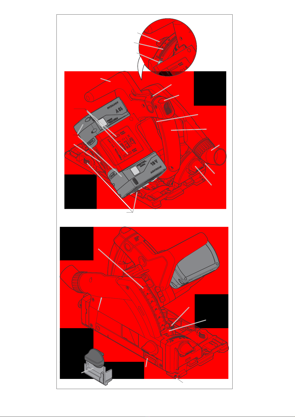
Function of the guide wedge [5-5]
a.
Use the correct saw blade for the guide wedge.
To ensure that the guide wedge functions proper-
ly, make sure the blade core of the saw blade is
thinner than the guide wedge and that the tooth
width is greater than the thickness of the guide
wedge.
b.
Do not operate the saw if the guide wedge is
bent.
Even the slightest problem can cause the
protective cover to close more slowly.
2.3 Further safety instructions
– Avoid blockages in the protective cover (e.g. plas-
tic) as otherwise the safety function may be com-
promised.
–
Harmful/poisonous dust may arise when work-
ing (e.g. paint products containing lead and
some types of wood).
Contact with or inhalation
of this dust may pose a risk for the operating per-

TSC 55 REB
17
GB
sonnel or persons in the vicinity. Observe the
safety regulations applicable in your country.
Wear a P2 respiratory mask to protect
your health.
–
Festool electric power tools must only be in-
stalled on work tables provided by Festool for
this purpose.
If the tool is installed in another, or
self-made, work table, it can become unstable
and result in serious accidents.
2.4 Aluminium processing
When sawing aluminium, the following mea-
sures must be taken for safety reasons:
– Connect the machine to a suitable dust extractor.
– Regularly remove dust deposits from the motor
housing.
– Use an aluminium saw blade.
– Close the viewing window/chipguard.
– When sawing panels, they must be lubricated
with paraffin but thin-walled profiles (up to 3
mm) can be sawed without lubrication.
2.5 Emission levels
Levels determined in accordance with EN 60745 are
typically:
Vibration emission value a
h
(vector sum for three
directions) and uncertainty K measured in accor-
dance with EN 60745:
The specified emission values (vibration, noise)
– are used to compare machines.
– They are also used for making preliminary esti-
mates regarding vibration and noise loads during
operation.
– They represent the primary applications of the
power tool.
Increase possible for other applications, with other
insertion tools or if not maintained adequately. Take
note of idling and downtimes of machine!
3Technicaldata
4 Machine features
Wear protective goggles.
Sound pressure level L
PA
= 89 dB(A)
Noise level L
WA
= 100 dB(A)
Measuring uncertainty allow-
ance
K = 3 dB
CAUTION
Operating noise
Damage to hearing
Use ear protection!
Vibration emission level (3 directions)
Cutting wood a
h
< 2,5 m/s
2
Cutting metal a
h
= 2,8 m/s
2
Uncertainty K = 1,5 m/s
2
Cordless plunge-cut saw TSC 55 REB
Motor voltage 14,4 - 2 x 18 V
Speed (idle) 1 x 18 V 2650 - 3800 min
-1
Speed (idle) 2 x 18 V 2650 - 5200 min
-1
Inclination -1° to 47°
Cutting depth at 0° 0 - 55
Cutting depth at 45° 0 - 43
Saw blade dimensions 160 x 2,2 x 20
Weight without battery pack 3,9
[1-1]
Handles
[1-2]
Rotary knobs for angle adjustment
[1-3]
Angle scale
[1-4]
Lever for changing blades
[1-5]
Switch-on lock
[1-6]
On/Off switch
[1-7]
Extractor connector
[1-8]
Release buttons for undercuts
-1° to 47°
[1-9]
Adjustable jaws
[1-10]
Speed control
[1-11]
Battery packs
[1-12]
Capacity display
[1-13]
Split scale for cutting depth stop (with/
without guide rail)
[1-14]
Cutting depth adjusting screw for resharp-
ened saw blades
[1-15]
Cutting depth stop
[1-16]
Cut indicator
[1-17]
Viewing window / chipguard
[1-18]
Splinterguard

18
TSC 55 REB
GB
5 Intended use
Cordless circular saws are designed for sawing
wood, materials similar to wood, plaster and ce-
ment-bonded fibre materials and plastics. When
fitted with special saw blades for aluminium of-
fered by Festool, the machines can also be used for
sawing aluminium.
Only saw blades with the following specifications
may be used: Saw blade diameter 160 mm, cutting
width 2,2 mm, location hole 20 mm, max. standard
blade thickness 1,8 mm, suitable for speeds up to
9500 min
-1
. Never use abrasive wheels in the ma-
chine.
The machine is designed and approved for use by
trained persons or specialists only.
The user is liable for improper or non-in-
tended use.
6 Commissioning
6.1 Changing the battery pack
Removing the battery pack [2 A]
Inserting the battery pack [2 B]
Please note!
Machine operation is only possible
under the following conditions
[2 C]
:
Both battery packs are used. Maximum
power with two battery packs (36 V).
Only the lower battery pack is used. Less
power with one battery pack (14.4 V/18 V).
6.2 Capacity display
The capacity display
[1-12]
automatically displays
the charge state of the battery pack
[1-6]
when the
ON/OFF switch is actuated:
7 Settings
7.1 Electronics
Smooth start-up
The electronically controlled smooth start-up en-
sures that the machine starts up jolt-free.
Constant speed
The motor speed remains constant through elec-
tronic control to ensure a uniform cutting speed
even when under load.
Speed control
You can regulate the speed steplessly within the
speed range using the adjusting wheel
[1-10]
(see
Technical data). This enables you to optimise the
cutting speed to suit the surface (see table 1).
Current limiting
Current limiting prevents excessive current con-
sumption under extreme overload, which can lead
to a decrease in the motor speed. The motor imme-
diately restarts after the load is removed.
Brake
The TSC 55 REB is fitted with an electronic brake.
When the saw is switched off, the saw blade slows
to a stop electronically within approx. 2 seconds.
Temperature cut-out
When exceeding a certain engine temperature lev-
el, the machine power supply and speed are
capped. The power tool continues operating at re-
duced power to allow the ventilator to cool the mo-
tor rapidly. The power tool resumes to full perfor-
mance automatically once the motor has cooled
sufficiently.
7.2 Adjusting the cutting depth
The cutting depth can be adjusted to between 0 – 55
mm on the cutting depth stop
[3-1]
:
The sawing unit can now be pressed down to the set
cutting depth.
70 - 100 %
40 - 70 %
15 - 40 %
< 15 %
Recommendation:
Charge bat-
tery pack before further use.
LED red – lit continuously:
bat-
tery, electronics or motor tem-
perature is outside the permitted
range.
LED red – flashing:
indicates a
general fault, e.g. incomplete
contact, short circuit, battery
pack faulty, etc.
WARNING
Risk of injury, electric shock
Always disconnect the battery packs from the
machine before performing any type of work on
the machine!
Cutting depth without guide rails
max. 55 mm
Cutting depth with guide rail FS
max. 51 mm
+FS

TSC 55 REB
19
GB
7.3 Adjusting the cutting angle
between 0° and 45°:
Unscrew the rotary knobs
[4-1]
.
Swivel the sawing unit to the desired cutting an-
gle
[4-2]
.
Tighten the rotary knobs
[4-1]
.
Both positions (0° and 45°) are set at the factory
and can be readjusted by the after-sales service
team.
When making angled cuts, slide the viewing
window/splinterguard to the highest posi-
tion!
to undercut -1° and 47°:
Swivel the saw unit to the end position (0°/45°)
as described above.
Pull out the release button
[4-3]
slightly.
Pull release button
[4-4]
as well for -1° under-
cuts.
The saw unit engages in the -1°/47° position.
Tighten the rotary knobs
[4-1]
.
7.4 Changing the saw blade
Swivel the machine to 0° before replacing the
saw blade and adjust the maximum cutting
depth.
Turn the lever
[5-3]
as far as the stop.
Operate lever
[5-3]
only when the machine is at
a standstill
!
Push the saw down until it engages.
Open the screw
[5-6]
using the Allen key
[5-2]
.
Remove the saw blade
[5-7]
.
Insert a new saw blade.
The direction of rotation of the saw blade
[5-8]
and machine
[5-4]
must match!
Serious injuries may occur in the event of
non-compliance.
Insert the outer flange
[5-9]
so that the pulling
peg engages in the recess of the inner flange.
Check screws and flange for dirt con-
tamination and only use clean and un-
damaged parts!
Tighten the screw
[5-6]
.
Pull the lever
[5-3]
back.
7.5 Fitting the viewing window/splinter-
guard [6]
The
viewing window
(transparent)
[6-1]
provides a
view of the saw blade and optimises dust ex-
traction.
With 0° cuts, the
splinterguard
(green)
[6-2]
also
improves the quality of the cutting edge of the
sawn-off workpiece on the upper side.
Insert the splinterguard
[6-2]
.
Screw the rotary knob
[6-3]
through the long
hole in the splinterguard.
Make sure that the nut
[6-4]
is seated securely
in the splinterguard.
Use only knob that comes with your circular
saw.
The knob of an other saw may be to
long and block the blade.
You must bed in the splinterguard before using it:
Set the machine to maximum cutting depth.
Set the machine speed to 6.
7.6 Dust extraction
Independent extraction
Secure the connection piece
[7-2]
of the dust
collection bag
[7-3]
at the extractor connector
with a clockwise rotation
[7-1]
.
To empty remove the connection piece
[7-2]
of
the dust collection bag from the extractor con-
nector
[7-3]
with an anti-clockwise rotation
[7-
1]
.
Festool mobile dust extractor
A Festool mobile dust extractor with an extractor
hose diameter of 27 mm or 36 mm (36 mm recom-
mended due to the reduced risk of clogging) can be
connected to the extractor connector
[7-1]
.
The adapter on a suction hose Ø 27 is inserted into
the angle adapter
[7-4]
. The adapter on a suction
hose Ø 36 is inserted over the angle adapter
[7-4]
.
CAUTION
Hot and sharp tools
Risk of injury
Do not use insert tools that are blunt or defec-
tive.
Wear protective gloves.
WARNING
Dust hazard
Dust can be hazardous to health. Always work
with a dust extractor.
Always read applicable national regulations be-
fore extracting hazardous dust.

20
TSC 55 REB
GB
8 Working with the machine
Please observe all mentioned safety infor-
mations and the following rules when work-
ing:
– Only guide the power tool towards the workpiece
when it is switched on.
– Check the installation fixture prior to use and do
not use the machine if the fixture does not func-
tion correctly.
– After dropping check the power tool and the saw
blade for damage. Have the damaged parts re-
paired before use. Damaged machines may lead
to injuries and cause the machine to be unsafe.
– Always secure the workpiece in such a manner
that it cannot move while being processed.
– Always hold the machine with two hands at the
handles
[1-1]
when performing work. This re-
duces the risk of injury and is a prerequisite for
precise work.
– Always push the machine forwards
[10-2]
, never
draw the machine towards yourself.
– Adapt the fast-feed speed to prevent the cutters
on the saw blade from overheating and prevent
plastic materials from melting during cutting.
– Make sure that all rotary knobs
[1-2]
are tight-
ened before starting work.
– Check that the saw blade is seated securely.
– Static charge may occur when sawing (e.g. MDF).
For work that generates dust, wear a dust
mask.
8.1 Switch on/off
Slide the switch-on lock
[1-5]
upwards and press
the on/off switch
[1-6]
(press = ON / release = OFF).
Pressing the switch-on lock unlocks the
plunging mechanism. The saw unit can then
be moved downwards. This causes the saw
blade to emerge from the protective cover.
8.2Acoustic warning signal
Acoustic warning signals sound and the machine
switches off in the following operating states:
Change the battery
Reduce the machine load
8.3 Sawing along the scribe mark
The cutting indicator
[8-2]
displays the cutting line
for 0° and 45° cuts (without guide rail).
8.4 Cutting sections
Place the machine with the front part of the saw ta-
ble on the workpiece, switch the machine on, press
it down to the preset cutting depth and push it for-
ward in the cutting direction.
8.5 Sawing cut outs (plunge cuts)
In order to avoid kickbacks, the following in-
structions must be observed without fail
when plunge cutting:
– Always place the machine with the rear edge of
the saw table against a fixed stop.
– When working with the guide rail, place the ma-
chine against the kickback stop FS-RSP (acces-
sory)
[10-4]
clamped to the guide rail.
Procedure
Position the machine on the workpiece and
push up against a stop (kickback stop).
Switch on the machine.
Push down the machine slowly to the preset
cutting depth and then push forwards in the cut-
ting direction.
The markings
[8-1]
indicate the absolute front and
the absolute rear cutting points of the saw blade
(dia. 160 mm) when using the saw at maximum cut-
ting depth with the guide rail.
8.6 Gypsum and cement-bound fibreboards
Due to the high volume of dust, it is recommended
to use the cover ABSA-TS55 (accessories) which
can be mounted at the side at the protective cover
and a Festool mobile dust extractor.
9 Service and maintenance
Customer service and repair
only
through manufacturer or service
workshops: Please find the nearest
address at: www.festool.com/service
Only use original Festool spare parts!
Order No. at: www.festool.com/service
Battery low or machine overloaded:
peep
WARNING
Risk of injury, electric shock
Always disconnect the battery pack from the
machine before any cleaning or maintenance!
All maintenance and repair work which requires
the motor housing to be opened, must only be
carried out by an authorised service workshop.
EKAT
1
235
4

+FS
3
4
-1°
-1° / 47°
0° - 45°
3-1
4-1
4-2
4-1
4-3
47°
4-4
-1°

5
6
6-3
6-1
5-1
5-2
5-4
5-5
5-6
5-7
5-8
5-3
5-9
6-4
6-2

7
8
8-1
8-2
1
2
1
7-1
7-2
7-3
7-4
2

10
10-1
10-2
10-5
10-3
10-4
9-2
99-1
Other manuals for TSC 55 REB
5
Table of contents