manuals.online logo
Brands
  1. Home
  2. •
  3. Brands
  4. •
  5. Festool
  6. •
  7. Planer
  8. •
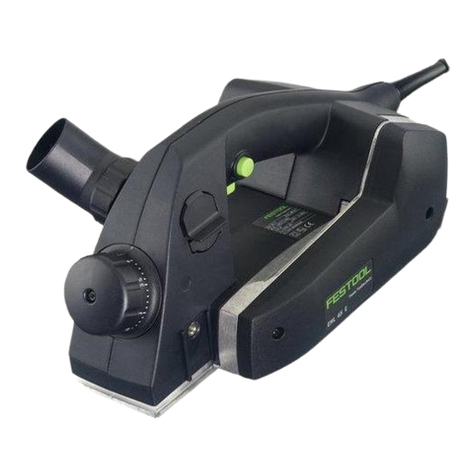
  9. Festool EHL 65 E User manual

Festool EHL 65 E User manual

468 035_002
Festool GmbH
Wertstraße 20
D-73240 Wendlingen
Telefon: 07024/804-0
Telefax: 07024/804-608
http://www.festool.com
EHL 65 E
Bedienungsanleitung/Ersatzteilliste*) 4 - 6
Operating Instructions/Spare parts list*) 7 - 9
Mode d’emploi/Liste de pièces de rechange*) 10 - 12
Instrucciones de servicio/Lista de piezas de repuesto*) 13 - 15
Istruzioni d’uso/Elenco parti di ricambio*) 16 - 18
Gebruiksaanwijzing/Lijst met reserveonderdelen*) 19 - 21
Bruksanvisning/Reservdelslista*) 22 - 24
Käyttöohje/Varaosaluettelo*) 25 - 27
Driftsvejledning/Reservedelsliste*) 28 - 30
Bruksanvisning/Reservedelsliste*) 31 - 33
Instruções de uso/Lista de peças sobresselentes*) 34 - 36
Ðóêîâîäñòâî ïî ýêñïëóàòàöèè/Ïåðå÷åíü çàïàñíûõ ÷àñòåé*) 37 - 39
Návod k obsluze/Seznam náhradních dílù*) 40 - 42
Instrukcja obs³ug/Lista czêœci zamiennych*) 43 - 45
Seen at Ideal Tools.
1.1
1.2
1.4
1.5
1.6
1.7
1.9
1.10
1.11
1.12
1.13
1.14
1.8
1.3
1
Seen at Ideal Tools.
2.42.1
4.1
2.2 2.52.3
2.11 2.10 2.9 2.8 2.7 2.6
2
3
4
Seen at Ideal Tools.
7
Technical data EHL 65 E
Power 720 W
Speed (no load) 15 600 rpm
Plane width 65 mm
Chip thickness 0 - 4 mm
Max. rebate depth 23 mm
Weight (excluding cable) 2.4 kg
Degree of protection / II
The specified illustrations can be found
at the beginning of the operating instruc-
tions.
1 Intended use
The tool together with the available Festool
accessories is designed for processing
wood, soft plastics and similar materials.
The user is liable for damage and in-
jury resulting from incorrect usage!
2 Safety instructions
2.1 General Safety Rules
Before using the machine, read all
safety instructions and these ope-
rating instructions carefully and
thoroughly.
Save all enclosed documents and pass the
machine with all these documents only.
2.2 Tool-specific safety rules
Wait for the cutter to stop before setting
the tool down. An exposed cutter may en-
gage the surface leading to possible loss of
control and serious injury.
Wear suitable personal pro-
tection equipment: Ear pro-
tection to reduce the risk of
damaging your hearing; Pro-
tective goggles; Face mask
to reduce the risk of inhaling
harmful dust; Protective
gloves when handling tools
and coarse materials
2.3 Noise and vibration information
The typical values determined in accor-
dance with EN 60745 are:
Sound-pressure level 82 dB(A)
Sound-power level 93 dB(A)
Measuring uncertainty allowance K = 4 dB
Wear ear protection!
Measured acceleration < 2.5 m/s²
3 Power supply and start-up
The mains voltage must correspond
to the specification on the rating
plate.
To switch on, first press the switch lock
(2.5) and then the switch (2.4) (press =
ON, release = OFF).
4 Electronics
The tool has full-wave electronics
with the following features:
Smooth start-up
The smooth start-up ensures the router
starts up jolt-free.
Constant speed
The pre-selected speed remains constant
whether the machine is in operation or in
neutral position.
Temperature control
To prevent overheating, the safety electro-
nics switches the machine off when it rea-
ches a critical motor temperature. Let the
machine cool down for approx. 3-5 minutes
before using it again. The machine requires
less time to cool down if it is running, i.e.
in neutral position.
5 Chip thickness adjustment
The planing depth can be adjusted by tur-
ning the rotary knob (2.1) (turn to the right
= larger planing depth, turn to the left =
smaller planing depth). The planing depth
which has been set can be read at the mark
(2.3) for the rotary knob scale (2.2). Adjus-
tment by one scale mark corresponds to a
change in planing depth of 0.1 mm.
The max. planing depth is 4 mm. So as no
to overload the machine, we recommend
that a maximum planing depth of 2.5 mm
be set with a plane width > 40 mm.
6 Changing cutters
Use only cutters which are sharp and
undamaged. Blunt cutters increase
the danger of kick-back and reduce
the planing quality obtained.
Seen at Ideal Tools.
8
- Always disconnect the mains plug from
the socket before changing the cutter.
- Loosen the locking screw (2.9) by approx.
2 revolutions with the Allan key (2.6) and
remove the cutter from the cutter shaft.
- Clean the cutter slot before inserting the
new cutter to ensure a correct fit.
- Then insert the new cutter (488 503) into
the groove with the printed side facing the
rear planer platen (2.8).
- Before tightening the locking screws (2.9)
align the cutter with a ruler so that its front
edge (1.13) is flush with the sides of the
front (1.12) and rear (1.14) planer pla-
tens. Then tighten first the central locking
screw, followed by the two outer screws.
7 Dust extraction
The standard equipment for the pla-
ner includes devices to enable the
planer to be used with both the chip
collecting bag (1.1) (488 566) or a
suction hose (1.2) connected to a
dust extractor.
The connector for dust extraction can be
fitted on either side of the tool. To change
sides, press the toggle lever (1.11) down
firmly. This releases the lug on the outer
edge of the casing and the adapter (1.4)
can be pushed through the casing (Fig. 3).
The adapter (1.4) can now be inserted into
the casing opening (4.1) lug first up the
stop in the casing.
Either the chip collecting bag (1.1) or an
angle piece (1.3) for a suction hose adapter
(1.2) can be fitted to the adapter (1.4). The
chips can be deflected in any direction by
turning the angle piece.
A suction hose Ø 27 mm adapter is inserted
into the angle piece (1.3). A suction hose
Ø 36 mm adapter is fitted over the angle
piece (1.3).
8 Putting the planer down
When working with electric planers you
must remember that the planer shaft con-
tinues to run for a few seconds after the
tool is switched off.
The EHL 65 E has a support foot (2.7) at the
end of the platen so that it can be placed
safely on a work surface. If the electric tool
is taken up, the support foot automatical-
ly protrudes beyond the planer platen to
ensure that the planer shaft is always raised
above flat work surfaces when the planer
is put down.
Pay attention to the following when
putting the EHL 65 E down:
- check that the support foot is present and
fully operational,
- wait until the planer shaft comes to a
standstill before putting the tool down.
If the support foot should be found obst-
ructive during special planing work it can
be swung back out of the way and locked
in position.
9 Fitting the guides
9.1 Rebating depth guide (488 543)
The rebating depth guide (1.8) is mounted
in the threaded hole (1.10) on the front
right of the machine.
The stop can be infinitely adjusted to bet-
ween 0 and 23 mm in accordance with the
scale. The rebating depth which has been
set can be read against the notch (1.9).
9.2 Parallel guide
The parallel guide (1.7) is fitted with a ro-
tary knob (1.5) in the threaded hole (2.10)
on the left side of the tool.
When planing along an edge a planing width
of between 0 and 65 mm can be set with
the stop after loosening the catch (1.6).
10 Working with the EHL 65 E
- The surface to be planed must be free of
metallic objects.
- First set The desired chip thickness.
- Place The front platen onto The workpiece
but do not allow The planer head to come
into contact with The wood.
- Switch on the planer.
- Guide The planer over The workpiece so
that The platen rests flat on The workpi-
ece. Press on The front planer platen when
starting to plane and on The rear planer
platen (end of workpiece) when continuing
or finishing planing.
Seen at Ideal Tools.
9
10.1 Chamfering
The front planer platen is equipped with a
90° V groove (2.11) to allow the chamfering
of workpiece edges. This V groove is 2 mm
deep, thus producing a 2 mm edge chamfer
with the chip thickness setting 0.
10.2 Bench-mounted operation
The planer can be operated bench-mounted
in conjunction with the bench-mounting
device SE-EHL (488 524). Detailed instruc-
tions are supplied with the accessories.
11 Accessories, tools
For your own safety, use only ori-
ginal Festool accessories and spare
parts.
The accessory and tool order number can
be found in the Festool catalogue or on the
Internet under “www.festool.com”.
12 Maintenance and care
Always remove the power supply
plug from the socket before carrying
out any work on the machine.
All maintenance and repair work
which requires the motor casing to
be opened may only be carried out
by an authorised service centre.
The cool air openings in the motor casing
must always be kept clean and unobstruc-
ted to ensure air circulation.
The tool is fitted with special motor brus-
hes with an automatic cut-out. When the
brushes become worn the power supply is
shut off automatically and the tool comes
to a standstill.
13 Warranty
Our equipment is under warranty for at
least 12 months with regard to material or
production faults in accordance with nati-
onal legislation.
In the EU countries, the warranty period
for exclusively private use is 24 months (an
invoice or delivery note is required as proof
of purchase).
Damage resulting from, in particular, nor-
mal wear and tear, overloading, improper
handling, or caused by the user or other
damage caused by not following the opera-
ting instructions, or any fault acknowledged
at the time of purchase, is not covered by
the warranty.
Complaints will only be acknowledged if
the equipment has not been dismantled
before being sent back to the suppliers or
to an authorised Festool customer support
workshop.
Store the operating instructions, safety no-
tes, spare parts list and proof of purchase
in a safe place.
In addition, the manufacturer’s current
warranty conditions apply.
Note
We reserve the right to make changes to
the technical data contained in this infor-
mation as a result of ongoing research and
development work.
Seen at Ideal Tools.
46
CE-Konformitetserklæring. Vi erklærer på eget ans-
var at dette produktet er i overensstemmelse med
følgende normer eller normative dokumenter: EN
60 745, EN 55 014, EN 61 000 i henhold til bestemmelsene
i direktivene 98/37/EF, 89/336/EØF.
EG-Konformitätserklärung. Wir erklären in alleini-
ger Verantwortung, dass dieses Produkt mit den
folgenden Normen oder normativen Dokumenten
übereinstimmt:
EN 60 745, EN 55 014, EN 61 000 gemäß den Bestimmungen
der Richtlinien 98/37/EG, 89/336/EWG.
455 789/II/200405
EY-standardinmukaisuusvakuutus. Vakuutamme yk-
sinvastuullisina, että tuote on seuraavien standardien
ja normatiivisten ohjeiden mukainen: EN 60 745,
EN 55 014, EN 61 000 direktiivien 98/37/EY, 89/336/EY
määräysten mukaan.
EG-konformitetsförklaring. Vi förklarar i eget ansvar,
att denna produkt stämmer överens med följande nor-
mer och normativa dokument: EN 60 745, EN 55 014,
EN 61 000 enligt bestämmelserna i direktiven 98/37/EG,
89/336/EEG.
EG-conformiteitsverklaring. Wij verklaren op eigen
verantwoordelijkheid dat dit produkt voldoet aan de
volgende normen of normatieve documenten. EN 60
745, EN 55 014, EN 61 000 conform de richtlijnen 98/37/EG,
89/336/EEG.
CE-Dichiarazione di conformità. Dichiariamo sotto la
nostra esclusiva responsabilità che il presente pro-
dotto è conforme alle norme e ai documenti normati-
vi seguenti: EN 60 745, EN 55 014, EN 61 000 conformemente
alle normative delle direttive 98/37/CE, 89/336/CEE.
Oœwiadczenie o zgodnoœci CE. Niniejszym oœwi-
adczamy z ca³¹ odpowiedzialnoœci¹, ¿e wyrób
ten odpowiada nastêpuj¹cym normom wzglêdnie
dokumentom normatywnym: EN 60 745, EN 55 014, EN
61 000 zgodnie z postanowieniami wytycznych 98/37/EG,
89/336/EWG.
Leiter Forschung und Entwicklung
Manager Research and Development
Directeur de recherce et développement
Festool GmbH
Wertstr. 20
D-73240 Wendlingen
Dr. Johannes Steimel
EC-Declaration of Conformity: We declare at our
sole responsibility that this product is in conformity
with the following standards or standardised docu-
ments:
EN 60 745, EN 55 014, EN 61 000 in accordance with the
regulations 98/37/EC, 89/336/EEC.
CE-Declaração de conformidade: Declaramos, sob
a nossa exclusiva responsabilidade, que este pro-
duto corresponde às normas ou aos documentos
normativos citados a seguir:
EN 60 745, EN 55 014, EN 61 000 segundo as disposições
das directivas 98/37/CE, 89/336/CEE.
CE-Déclaration de conformité communautaire. Nous
déclarons sous notre propre responsabilité que ce
produit est conforme aux normes ou documents de
normalisation suivants: EN 60 745, EN 55 014, EN 61 000
conformément aux prescriptions des directives 98/37/CE,
89/336/CEE.
Çàÿâëåíèå î êîíôîðìíîñòè ÑÅ. Ìû çàÿâëÿåì
â åäèíîëè÷íîé îòâåòñòâåííîñòè, ÷òî äàííîå
èçäåëèå ñîîòâåòñòâóåò òðåáîâàíèÿì ñëåäóþùèõ
ñòàíäàðòîâ èëè íîðìàòèâîâ: EN 60 745, EN 55 014, EN 61
000 â ñîîòâåòñòâèè ñ ïîñòàíîâëåíèÿìè äèðåêòèâ ÅÑ 98/37,
ÅÝÑ 89/336.
CE-Declaración de conformidad. Declaramos bajo
nuestra exclusiva responsabilidad que este producto
corresponde a las siguientes normas o documentos
normalizados: EN 60 745, EN 55 014, EN 61 000 conforme
a las prescripciones estipuladas en las directrices 98/37/CE,
89/336/CEE.
Prohlášení o souladu s normami CE. Prohlašujeme na
vlastní zodpovìdnost, že tento výrobek odpovídá nás-
ledujícím normám nebo normativním dokumentùm:
EN 60 745, EN 55 014, EN 61 000 v souladu s ustanoveními
smìrnic 98/37/EHS, 89/336/EHS.
EF-konformitetserklæring: Vi erklærer at have alene
ansvaret for, at dette produkt er i overensstem-
melse med de følgende normer eller normative
dokumenter:
EN 60 745, EN 55 014, EN 61 000 i henhold til bestemmelser-
ne af direktiverne 98/37/EF, 89/336/EØF.
Seen at Ideal Tools.

Other manuals for EHL 65 E

5

Other Festool Planer manuals

Festool HL 850 E User manual

Festool

Festool HL 850 E User manual

Festool HL 850 EB User manual

Festool

Festool HL 850 EB User manual

Festool EHL 65 E User manual

Festool

Festool EHL 65 E User manual

Festool EHL 65 EQ Installation instructions

Festool

Festool EHL 65 EQ Installation instructions

Festool HL 850 E User manual

Festool

Festool HL 850 E User manual

Festool HL 850 E User manual

Festool

Festool HL 850 E User manual

Festool HL 850 EB User manual

Festool

Festool HL 850 EB User manual

Festool EHL 65 E User manual

Festool

Festool EHL 65 E User manual

Festool HL 850 E User manual

Festool

Festool HL 850 E User manual

Festool EHL 65 E User manual

Festool

Festool EHL 65 E User manual

Festool EHL 65 EQ User manual

Festool

Festool EHL 65 EQ User manual

Festool HL 850 E User manual

Festool

Festool HL 850 E User manual

Festool EHL 65 E User manual

Festool

Festool EHL 65 E User manual

Festool EHL 65 E User manual

Festool

Festool EHL 65 E User manual

Festool EHL 65 EQ Installation instructions

Festool

Festool EHL 65 EQ Installation instructions

Festool PL 205 E Installation instructions

Festool

Festool PL 205 E Installation instructions

Festool EHL 65 EQ Installation instructions

Festool

Festool EHL 65 EQ Installation instructions

Festool HL 850 E User manual

Festool

Festool HL 850 E User manual

Festool PLANEX LHS 225 EQ User manual

Festool

Festool PLANEX LHS 225 EQ User manual

Festool HL 850 E User manual

Festool

Festool HL 850 E User manual

Popular Planer manuals by other brands

Makita HG 1100 instruction manual

Makita

Makita HG 1100 instruction manual

Grizzly G0633/G0634 owner's manual

Grizzly

Grizzly G0633/G0634 owner's manual

Charnwood W583 owner's manual

Charnwood

Charnwood W583 owner's manual

Grizzly G0634Z  insert Manual insert

Grizzly

Grizzly G0634Z insert Manual insert

Makita DKP140 instruction manual

Makita

Makita DKP140 instruction manual

Makita 2012NB instruction manual

Makita

Makita 2012NB instruction manual

Makita DKP180ZJ instruction manual

Makita

Makita DKP180ZJ instruction manual

Craftsman 113.206891 owner's manual

Craftsman

Craftsman 113.206891 owner's manual

Maktec MT191 instruction manual

Maktec

Maktec MT191 instruction manual

Shop fox SHOP FOX W1742S  insert Manual insert

Shop fox

Shop fox SHOP FOX W1742S insert Manual insert

Invicta Thicknesser DGI-63D Operator's manual

Invicta

Invicta Thicknesser DGI-63D Operator's manual

General International 30-125CE M1 operating instructions

General International

General International 30-125CE M1 operating instructions

Robland D 510 manual

Robland

Robland D 510 manual

Silverline 128891 manual

Silverline

Silverline 128891 manual

Jet 707400 Specifications

Jet

Jet 707400 Specifications

Makita 1911B instruction manual

Makita

Makita 1911B instruction manual

Graphite 59G678 manual

Graphite

Graphite 59G678 manual

Makita DKP181 instruction manual

Makita

Makita DKP181 instruction manual

manuals.online logo
manuals.online logoBrands
  • About & Mission
  • Contact us
  • Privacy Policy
  • Terms and Conditions

Copyright 2025 Manuals.Online. All Rights Reserved.