Fhiaba 599 Series User manual

INSTALLATION GUIDE
NOTICE D’INSTALLATION
EN
FR

IMPORTANT
Dimensions in parentheses are in inches: mm(in).
Weights in parentheses are in pounds: kg (lb).
Temperatures in parentheses are in Fahrenheit degrees: °C(°F)

1
3
3
4
5
6
7
9
10
11
12
15
16
18
19
20
21
22
23
24
25
27
28
30
32
33
34
35
36
Installation Guide
EnglishFrançais
Index
Page
Important Instructions
Important safety instructions
Children safety
Technical requirements
Appliance features and installation requirements
Integrated60 installation niche features
Integrated70 installation niche features
StandPlus installation niche features
X-Pro installation niche features
Preparing to install
Transport to installation site and unpacking
Niche Dimensions and Installation Styles: Integrated Series
Niche Dimensions and Installation Styles: StandPlus and X-Pro Series
Electrical and Water connection
Levelling
Panels mounting
Decorative door and Bottom-Drawer panels layout
Decorative panels layout for Fridge with one Bottom-Drawer
Decorative panels layout for Fridge with two Bottom-Drawers
Decorative panels layout for Fridge with Glass door and one Bottom-Drawer
Decorative panels layout for Fridge with Glass door and two Bottom-Drawers
Panels Dimensions One Bottom - Drawer (models)
Panels Dimensions Two Bottom - Drawers (models)
Mounting the handles on Integrated units
Mounting panels to the door and the drawer of Integrated units
Installation
Built-in installation of single appliance
Built-in installation of two or more appliances
Completing the installation
Anti-tipping safety assembly
Mounting handles on stainless front
Air circulation
Ventilation
Post installation control
Start Up

2www.fhiaba.com · [email protected] · Tel +39 (0)434 420160 · Fax +39 (0)434 420161

3
Installation Guide
Series: All
EnglishFrançais
Symbols used in the Guide
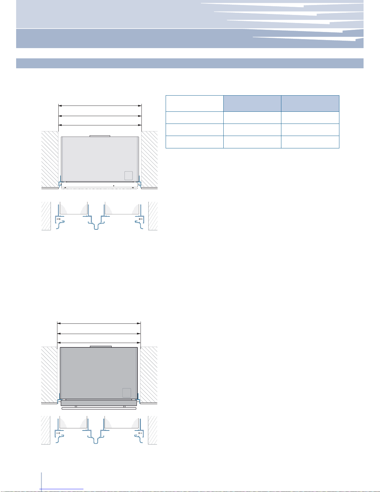
599 Series w: 587 mm (23 1/8 in)/ h: 2134 mm (84 in)/ d: 575 mm (22 1/2 in)
749 Series w: 737 mm (29 in)/ h: 2134 mm (84 in)/ d: 575 mm (22 1/2 in)
899 Series w: 887 mm (35 in)/ h: 2134 mm (84 in)/ d: 575 mm 575 mm (22 1/2 in)
599 Series w: 587 mm (23 1/8 in)/ h: 2134 mm (84 in)/ d: 675 mm (26 5/8 in)
749 Series w: 737 mm (29 in)/ h: 2134 mm (84 in)/ d: 675 mm (26 5/8 in)
899 Series w: 887 mm (35 in)/ h: 2134 mm (84 in)/ d: 675 mm (26 5/8 in)
599 Series w: 587 mm (23 1/8 in)/ h: 2134 mm (84 in)/ d: 694 mm (27 1/4 in)
749 Series w: 737 mm (29 in)/ h: 2134 mm (84 in)/ d: 694 mm (27 1/4 in)
899 Series w: 887 mm (35 in)/ h: 2134 mm (84 in)/ d: 694 mm (27 1/4 in)
599 Series w: 587 mm (23 1/8 in)/ h: 2134 mm (84 in)/ d: 700 mm (27 1/2 in)
749 Series w: 737 mm (29 in)/ h: 2134 mm (84 in)/ d: 700 mm (27 1/2 in)
899 Series w: 887 mm (35 in)/ h: 2134 mm (84 in)/ d: 700 mm (27 1/2 in)
599 Series w: 650 mm (25 5/8 in) / h: 2260 mm (89 in) / d: 800 mm (31 1/2 in)
749 Series w: 800 mm (31 1/2 in) / h: 2260 mm (89 in) / d: 800 mm (31 1/2 in)
899 Series w: 950 mm (37 3/8 in) / h: 2260 mm (89 in) / d: 800 mm (31 1/2 in)
599 Series up to 230 kg (507 lb)
749 Series up to 275 kg (606 lb)
899 Series up to 295 kg (650 lb)
Europe Version: AC 220-240V 50 Hz / North America Version: 110V 60Hz
Europe Version: Schuko 16 A plug / North America Version: 15 A
from 0.05 MPa to 0.5 MPa (0.5 Bar - 5 Bar)
3/4” female attachment
Customized panels mounting Kit
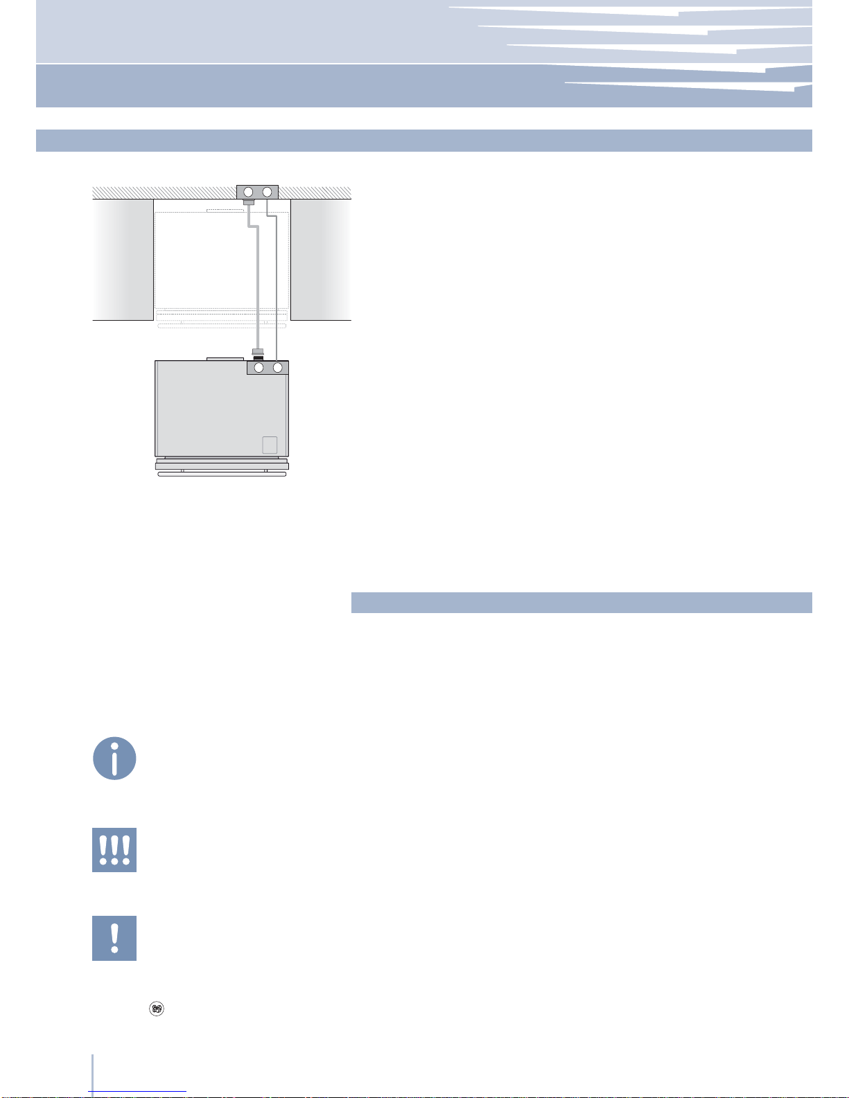
Anti-tipping Kit (B04000200)
Lateral connecting kit (KCLIT/KCLIH)
4 mm (1/8 in) allen wrench
Phillips head screwdriver
wood and percussion drill
2.5 mm (1/8 in) bit for wood
8 mm (3/8 in) bit for walls
17 mm (5/8 in) wrench
Appliance dimensions
Integrated 60
Appliance dimensions
Integrated 70
Appliance dimensions
StandPlus
Appliance dimensions
X-Pro
Appliance dimensions
with packaging
Weight with packaging
Voltage
Power supply cable
Potable water supply pressure
Water supply tube
Provided installation accessories
Additional equipment necessary
If this appliance is replacing an existing appliance which must be
removed or disposed of, make sure that it does not become a
dangerous trap for children by cutting its power supply cable and
rendering it impossible to close the door.
Use the same caution at the end of the lifespan of the new ap-
pliance.
Note
Tips for the correct use of the appliance
Warning
directions to prevent injury
Important
Directions to avoid appliance damage
Important safely instruction
Children safety
Appliance features and installation requirements

4
575 (22 ½)
525 (20 ⁄)
1293 (50 ⁄ )474 (18 ⁄)
248 (9
¾
)
231 (9
⁄
)
465 (18 ⁄)
525 (20 ⁄)
248 (9
¾
)
231 (9
⁄
)
465 (18 ⁄)
575 (22 ½)
1168(46)
330 (13)
259 (10
¼
)
I599: 587 (23 ⁄)
I749: 737 (29)
I899: 887 (35)
721 (28 ⁄)
2134 (84) ±12,7 (½)
846 (33 ¼)
2134 (84) ±12,7 (½)
I749: 737 (29)
I899: 887 (35)
105°
947 (37 ¼)
I899: 79 (3 ⁄)
I749: 53 (2 ⁄)
I599: 27 (1 ⁄)
I899: 1420 (55 ⁄)
I749: 1270 (50)
I599: 1120 (44 ⁄)
E
W
140 (5 ½) 140 (5 ½)
100 (4)
100 (4)
I899: 900 (35 ⁄)
I599: 600 (23 ⁄)
I749: 750 (29 ½)
A A
min 2134 (84)
525 (20 ⁄)
575 (22 ½)
10 (⁄)
I899: 899 (35)
I749: 749 (29 ½)
I599: 599 (23 ⁄)
A
E
W
Installation niche features: Integrated Series 60 depth
area to be left clear for the anti-tipping brackets
area to be left clear for the power supply cable
and water supply hose
Minimum Niche Height
2134 (84)
Minimum Niche Width
I899: 900 mm (35 3/8 in)
I749: 750 mm (29 1/2 in)
I599: 600 mm (23 5/8 in)
Door Swing Clearance
I899: 1420 mm (55 7/8 in)
I749: 1270 mm (50 in)
I599: 1120 mm (44 1/8 in)
Door Opening Angle
105°
Width
I899: 887 mm (35 in)
I749: 737 mm (29 in)
I599: 587 mm (23 1/8 in)
Height
2134 mm (84 in) ± 12,7mm (1/2 in)
Depth with door (without panel)
575 mm (22 1/2 in)

5
105°
1047 (41 ¼)
G899: 1520 (60)
G749: 1370 (54)
G599: 1220 (48)
G899: 79 (3 ⁄)
G749: 53 (2 ⁄)
G599: 27 (1 ⁄)
E
W
A A
min 2134 (84)
140 (5 ½) 140 (5 ½)
100 (4)
100 (4)
G899: 900 (35 ⁄)
G599: 600 (23 ⁄)
G749: 750 (29 ½)
675 (26 ⁄)
565 (22 ¼)
625 (24 ⁄)
1293 (50 ⁄)474 (18 ⁄)
248 (9
¾
)
231 (9
⁄
)
G599: 587 (23 ⁄)
G749: 737 (29)
G899: 887 (35)
2134 (84) ±12,7 (½)
721 (28 ⁄)
675 (26 ⁄)
565 (22 ¼)
625 (24 ⁄)
248 (9
¾
)
231 (9
⁄
)
1168(46)
330 (13)
259 (10
¼
)
846 (33 ¼)
G749: 737 (29)
G899: 887 (35)
2134 (84) ±12,7 (½)
625 (24 ⁄)
675 (26 ⁄)
10 (⁄)
G899: 899 (35)
G749: 749 (29 ½)
G599: 599 (23 ⁄)
A
E
W
Installation Guide
EnglishFrançais
Installation niche features: Integrated Series 70 depth
area to be left clear for the anti-tipping brackets
area to be left clear for the power supply cable and
water supply hose
Minimum Niche Height
2134 (84)
Minimum Niche Width
G899: 900 mm (35 3/8 in)
G749: 750 mm (29 1/2 in)
G599: 600 mm (23 5/8 in)
Door Swing Clearance
G899: 1520 mm (60 in)
G749: 1370 mm (54 in)
G599: 1220 mm (48 in)
Door Opening Angle
105°
Width
G899: 887 mm (35 in)
G749: 737 mm (29 in)
G599: 587 mm (23 1/8 in)
Height
2134 mm (84 in) ± 12,7mm (1/2 in)
Depth with door (without panel)
675 mm (26 5/8 in)

6
694 (27 ¼)
680 (26 ¾)
128 (5)
731 (28 ¾)
485 (19 ⁄)1296 (50) 195 (7 ⁄)
625 (24 ⁄)
MG599: 587 (23 ⁄)
MG749: 737 (29)
MG899: 887 (35)
2134 (84) ±12,7 (½)
613 (24 ⁄)
105°
MG899: 120 (4
¾
MG749: 94 (3 ¾
)
MG599: 68 (2 ⁄
)
MG899:1502 (59 ⁄)
MG749: 1324 (52 ⁄)
MG599: 1296 (51)
1207 (47 ½)
69 (2 ¾)
694 (27 ¼)
37
(
1 ½
)
625 (24 ⁄)
MG899: 899 (35)
MG749: 749 (29 ½)
MG599: 599 (23 ⁄)
A
E
W
A A
E
W
min 2134 (84)
MG899: 900 (35 ⁄)
MG599: 600 (23 ⁄)
MG749: 750 (29 ½)
140 (5 ½) 140 (5 ½)
100 (4)
100 (4)
min 10 (⁄)
Installation niche features: StandPlus Series
area to be left clear for the anti-tipping brackets
area to be left clear for the power supply cable
and water supply hose
Minimum Niche Height
2134 (84)
Minimum Niche Width
MG899: 900 mm (35 3/8 in)
MG749: 750 mm (29 1/2 in)
MG599: 600 mm (23 5/8 in)
Door Swing Clearance
MG899: 1502 mm (59 1/8 in)
MG749: 1324 mm (52 1/8 in )
MG599: 1296 mm (51 in)
Door Opening Angle
105°
Width
MG899: 887 mm (35 in)
MG749: 737 mm (29 in)
MG599: 587 mm (23 1/8 in)
Height
2134 mm (84 in) ± 12,7mm (1/2 in)
Depth with door
694 mm (27 1/4 in)
Flush
IMPORTANT

7
625 (24 ⁄)
700 (27 ½)
128 (5) 485 (19 ⁄)1296 (50) 195 (7 ⁄)
758 (29 ⁄)
XG599: 587 (23 ⁄)
XG749: 737 (29)
XG899: 887 (35)
2134 (84) ±12,7 (½)
613 (24 ⁄)
105°
XG899: 138 (5 ⁄
)
XG749: 112 (4 ⁄
)
XG599: 86 (3 ⁄)
XG899: 1498 (59)
XG749: 1320 (52)
XG599: 1292 (50 ⁄)
1073 (42 ¼)
A A
E
W
min 2134 (84)
XG899: 900 (35 ⁄)
XG599: 600 (23 ⁄)
XG749: 750 (29 ½)
140 (5 ½) 140 (5 ½)
100 (4)
100 (4)
75 (3)
700 (27 ½)
58 (2 ¼)
XG899: 899 (35)
XG749: 749 (29 ½)
XG599: 599 (23 ⁄)
625 (24 ⁄)
10 (⁄)
A
E
W
min 10 (⁄)
Installation Guide
EnglishFrançais
Installation niche features: X-Pro Series
area to be left clear for the anti-tipping brackets
area to be left clear for the power supply cable
and water supply hose
Minimum Niche Height
2134 (84)
Minimum Niche Width
XG899: 900 mm (35 3/8 in)
XG749: 750 mm (29 1/2 in)
XG599: 600 mm (23 5/8 in)
Door Swing Clearance
XG899: 1498 mm (58 63/64 in)
XG749: 1320 mm (51 31/32 in)
XG599: 1292 mm (50 7/8 in)
Flush
IMPORTANT
Door Opening Angle
105°
Width
XG899: 887 mm (35 in)
XG749: 737 mm (29 in)
XG599: 587 mm (23 1/8 in)
Height
2134 mm (84 in) ± 12,7mm (1/2 in)
Depth with door
700 mm (27 1/2 in)

8
A
E
W
min 10 (⁄)
525 (20 ⁄)
600 (23 ⁄)
658 (25 ⁄)
128 (5) 485 (19 ⁄) 1296 (50) 195 (7 ⁄)
XI599: 587 (23 ⁄)
XI749: 737 (29)
XI899: 887 (35)
2134 (84) ±12,7 (½)
613 (24 ⁄)
105°
X899: 138 (5 ⁄)
X749: 112 (4 ⁄)
X599: 86 (3 ⁄)
XI899: 1402 (55 ¼)
XI749: 1224 (48 ¼)
XI599: 1196 (47 ⁄)
973 (38 ¼)
A A
min 2134 (84)
XI899: 900 (35 ⁄)
XI599: 600 (23 ⁄)
XI749: 750 (29 ½)
140 (5 ½) 140 (5 ½)
100 (4)
100 (4)
E W E W
75 (3)
600 (23 ⁄)
58 (2 ¼)
525 (20 ⁄)
10 (⁄)
XI899: 899 (35)
XI749: 749 (29 ½)
XI599: 599 (23 ⁄)
Installation niche features: X-Pro Series
area to be left clear for the anti-tipping brackets
area to be left clear for the power supply cable
and water supply hose
Minimum Niche Height
2134 (84)
Minimum Niche Width
XI899: 900 mm (35 3/8 in)
XI749: 750 mm (29 1/2 in)
XI599: 600 mm (23 5/8 in)
Door Swing Clearance
XI899: 1402 mm (55 1/4 in)
XI749: 1224 mm (48 1/4 in)
XI599: 1196 mm (47 1/8 in)
Flush
IMPORTANT
Door Opening Angle
105°
Width
XI899: 887 mm (35 in)
XI749: 737 mm (29 in)
XI599: 587 mm (23 1/8 in)
Height
2134 mm (84 in) ± 12,7mm (1/2 in)
Depth with door
600 mm (23 5/8 in)

9
1
4
1
2
3
Installation Guide
Series: All
EnglishFrançais
The appliance is very heavy.
Take maximum care during handling to
avoid injury.
The appliance should always be transport-
ed in an erect position.
Avoid at all costs leaning it on its front side.
Preparing the installation
Transport to installation site
and unpacking Since this is a large and heavy appliance, before transporting the ap-
pliance, check the access to the location where it will be installed
(door size, manoeuvring space in stairwells, etc.).
Theapplianceisattachedtothebaseofthepackaging(pallet)through
four bolts which can be removed using a 17 mm (5/8 in) wrench.
It is recommended to use a manual transporting device to move the
appliance to the installation site, and only at this point to remove the
base of the packaging.
The appliance should always be transported in an erect position.
If this is not possible, transport the appliance laying on its rear side.
Once at the installation site, the appliance, which is equipped with four
wheels, can be taken off the pallet and positioned in the installation
area.
Operate as follows:
Take off the four bolts 1securing the appliance to the pallet by
means of a 17 mm (5/8 in) open spanner.
Remove the Àxing brackets 3and 4.
To remove the front Àxing bracket 3, unscrew for one or two turns
the rear wheel adjusting bolt 2by means of a 13 mm (1/16 in) box
spanner.
From the back of the unit and by means of a suitable, high duty hand
trolley, take off the appliance and place it on the Áoor.
Be very careful to avoid any damage to Áoors. Delicate Áoors should be
protected with plywood, hard cardboard or similar material panels.

10
599: 600 (23 ⁄)
749: 750 (29 ½)
899: 900 (35 ⁄)
AAB
899
749
599
897 (35 1/4)900 (35 3/8)
750 (29 1/2)
600 (23 5/8)
747 (29 3/8)
597 (23 1/2)
599: 600 (23 ⁄)
749: 750 (29 ½)
899: 900 (35 ⁄)
AAB
Series: Integrated
Niche Dimensions and Installation Styles: Integrated Series
Panels WidthNiche
Series
A KCLITU: Lateral connection Kit
B KCCITU: Central connection Kit
European Version
A KCLMT: Lateral connection Kit
B KCCMT: Central connection Kit

11
914 (36
)
900 (35 3/8)
762
(30)750 (29 1/2)
614 (24 1/8)600 (23 5/8)
599: 600 (23 ⁄) / 614 (24 ⁄)
749: 750 (29 ½) / 762 (30)
899: 900 (35 ⁄) / 914 (36)
CCB
899
749
599
Installation Guide
EnglishFrançais
Series: StandPlus/X-Pro
Niche Dimensions and Installation Styles: StandPlus and X-Pro Series
MAXMIN
Series
NICHE
B KCCMT: Central connection Kit
C KCLXB: Lateral connection Kit

EW
EW
12
Series: All
The appliances are delivered from the factory for operation at either
230V AC - 50Hz (Europe, UK and other countries) or 115V AC - 60Hz
(US and Canada).
They are provided with a suitable supply cable and plug to be con-
nected to an appropriate 16A socket (Europe, UK and other coun-
tries) or 15A socket (US and Canada) provided with an efÀcient
grounding.
A circuit breaker should also be installed and should be easily ac-
cessible so that it can be easily switched off before performing any
installation or maintenance.
To connect to the water supply system (for appliances equipped with
ice makers) a tap with a male 3/4” connection should be provided,
which must also be easily accessible once the appliance is installed.
The appliance is provided with a water supply hose and seal kit which
is suitable for high water pressure and complies the Food Regula-
tions.
The water Àlter cartridge, which is provided with the appliance,
should be installed according to the accompanying instructions.
Use only the new hose and the new gaskets which are supplied with
the appliance. Discard any hose and gasket which may have al-
ready been installed.
The appliance should be connected only to
a drinkable water supply system.
The Built-in Fhiaba Àlter cannot make it safe
to drink any water which is not suitable for
human consumption.
Electrical and Water connection
Do not use extension cords or adapters.
Once the appliance has been connected to
the water system, turn the Ice Maker off (touch
the button on control panel to switch it off)
before the main water is shut off.
Energy: Alternatives and Home Automation
If energy is supplied through an alternative energy power source
(solar, geothermal, etc..) or if home automation systems are installed,
it is necessary to install the Alternative Energy Kit to integrate the unit
into the power grid.

2
1
13
Installation Guide
EnglishFrançais
Series: Integrated
Back of appliance
Water connection
Electrical connection
Operate as follows:
Unwind the electric cable and connect it directly to the wall socket.
Make sure the appliance is in the Stand-by condition and that all
lights are off; should it be not so press the Unit button to switch it off.
Fit one end of the water hose onto the connector at the appli-
ance’s back 1.
Fit the other end of the hose to the water tap, use the gaskets pro-
vided in the Owner’s Kit 2.

2
1
14 www.fhiaba.com · [email protected] · Tel +39 (0)434 420160 · Fax +39 (0)434 420161
Series: StandPlus/X-Pro
Operate as follows:
Unwind the electric cable and connect it directly to the wall socket.
Make sure the appliance is in the Stand-by condition and that all ights
are off; should it be not so press the Unit button to switch it off.
Connect the water line to the threaded connection at the base of the
unit, as in Àgure 1.
Fit the other end of the hose to the water tap, use the gaskets provided
in the Owner’s Kit 2.
Back of appliance
Front of appliance
Water connectionElectrical connection

15
1
2
1
2
Installation Guide
Series: All
EnglishFrançais
Adjust the appliance level by means of the front levelling feet
and the rear adjustable wheels.
Operate as follows:
After removing the bottom plinth or grille (it is kept in position by
magnets), adjust the height of the levelling feet 1by means of a 17
mm (5/8 in) open spanner.
Then adjust the height of the rear wheels by turning the front
adjusting bolts 2clockwise or anticlockwise as it may be required.
Remount the bottom plinth or grille.
Levelling

16
1
2
3
Series: Integrated
Decorative door and bottom-drawer panels layout
The dimensions of the panels are indicated in the table and draw-
ings on pages 14-17.
Nevertheless, according to the requirements for aligning with other
kitchen structures, the door panel can be higher than the upper
edge of the refrigerator door, and the drawer panel can be lower
than the edge of the drawer.
The panels must be mounted using special braces which attach
to adjustable devices provided on the door and drawer and with
brackets that anchor and adjust the panel’s vertical direction.
Braces, brackets and fixing screws are provided with the appliance
and must be applied to the panel as indicated.
Operate as follows:
To prepare the panels to be mounted on the appliance, follow
these steps, working on the back of the panel.
Door Panel
Trace, a line dividing the panel width in half 1.
Starting form the Bottom edge of the panel, mark the positioning
of the brackets 2.
Following the corresponding table, mark the external and then
the internal hole 3.

17
7
8
4
5
Installation Guide
EnglishFrançais
Series: Integrated
Position the brackets on each set of marks to make sure they are
aligned 4, then drill holes through the panel (pay close attention to
the panel’s thickness) 5.
Screw the brackets in place 6.
Drawer Panel
When preparing the Drawer Panel, follow the same instructions as
per the door panel, but make sure measurements are taken starting
from the top edge 7. The support bracket faces the opposite way
8(note imgs 4 and 8).

18
D E
D E
A
B C
F G
13 (⁄)
13 (⁄)
34 (1 ⁄)
34 (1 ⁄)
1285 (50 ⁄)
1163 (45 ¾)
660 (26)
157 (6 ⁄)
min 1390 (54 ¾)max 635 (25)
507,5 (21)
382 (15)
100 (4)
A897 (35 ¼) 897 (35 ¼) 747 (29 ⁄) 747 (29 ⁄) 597 (23 ½)
355,5 (14)
355,5 (14)
279 (11)
279 (11)
205 (8 ⁄)
205 (8 ⁄)261 (10 ¼)
261 (10 ¼)
187 (7 ⁄)
187 (7 ⁄)
111 (4 ⁄)
111 (4 ⁄)
418 (16 ½)
418 (16 ½)
343 (13 ¼)
343 (13 ¼)
276,5 (10 ⁄)
276,5 (10 ⁄)386 (15 ¼)
386 (15 ¼)
311 (12 ¼)
311 (12 ¼)
236,5 (9 ¼)
236,5 (9 ¼)
B
C
D
E
354,5 (14) 354,5 (14) 279,5 (11) 279,5 (11) 203,5(8)
597 (23 ½)
203,5(8)
F / G
Series: Integrated
Decorative panels layout for Fridge with one Bottom-Drawer (1T/0T)
Series 899
Hinge Left Hinge Left Hinge Left
Hinge Right Hinge Right Hinge Right
Series 749 Series 599
Holes positions
This manual suits for next models
2
Table of contents
Languages:
Other Fhiaba Refrigerator manuals

Fhiaba
Fhiaba Refrigerator User manual

Fhiaba
Fhiaba BI30BILO User manual

Fhiaba
Fhiaba Integrated Series User manual

Fhiaba
Fhiaba X-Pro 599 Series Guide

Fhiaba
Fhiaba S8990FR6U User manual

Fhiaba
Fhiaba 1T User manual

Fhiaba
Fhiaba XS8990TST6IU User manual

Fhiaba
Fhiaba S8990FZ6I User manual

Fhiaba
Fhiaba 1T User manual

Fhiaba
Fhiaba 0FR Series User manual