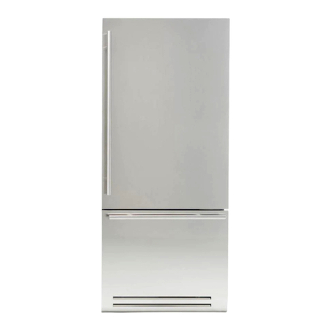
Fhiaba FP36FZC-RS1 User manual

Installation guide EN
Notice d’installation FR
Guía de instalación ES

www.fhiaba.com · www.thevettagroup.com · Info Line 1-855-4-FHIABA (1-855-434-4222) www.fhiaba.com · www.thevettagroup.com · Info Line 1-855-4-FHIABA (1-855-434-4222)www.fhiaba.com · www.thevettagroup.com · Info Line 1-855-4-FHIABA (1-855-434-4222) www.fhiaba.com · www.thevettagroup.com · Info Line 1-855-4-FHIABA (1-855-434-4222)

www.fhiaba.com · www.thevettagroup.com · Info Line 1-855-4-FHIABA (1-855-434-4222) www.fhiaba.com · www.thevettagroup.com · Info Line 1-855-4-FHIABA (1-855-434-4222)www.fhiaba.com · www.thevettagroup.com · Info Line 1-855-4-FHIABA (1-855-434-4222) www.fhiaba.com · www.thevettagroup.com · Info Line 1-855-4-FHIABA (1-855-434-4222)
3
INDEX EN
1
1.1
1.2
IMPORTANT INSTRUCTIONS
Important safety instructions.....................................................................................................................................
Child safety.......................................................................................................................................................................
4
4
4
2
2.1
2.2
2.3
2.4
2.5
2.6
2.7
TECHNICAL REQUIREMENTS
Appliance features and installation requirements..............................................................................................
Installation cutout features: panel ready columns..............................................................................................
Installation cutout features: panel ready................................................................................................................
Installation cutout features: cladded columns.....................................................................................................
Installation cutout features: cladded.......................................................................................................................
Installation cutout features: X-Pro............................................................................................................................
Installation cutout features: X-Pro colums............................................................................................................
5
5
6
8
10
12
14
18
3
3.1
3.2
3.3
3.4
PREPARING THE INSTALLATION
Transport to installation site and unpacking.........................................................................................................
Electrical and water connection................................................................................................................................
Energy: Alternatives and Home Automation.........................................................................................................
Leveling.............................................................................................................................................................................
22
22
22
23
24
4
4.1
4.2
CUTOUT DIMENSIONS
Cutout dimension for combined installation (for all models except XPro)...................................................
Flush installation with standard trims....................................................................................................................
25
25
25
5
5.1
5.2
5.3
5.4
5.5
5.6
5.7
5.8
5.9
5.10
5.11
5.12
PANELS MOUNTING
Overlay door panel layout...........................................................................................................................................
Overlay panels layout for appliance with one bottom-drawer.........................................................................
Overlay panels layout for appliance with two bottom drawers.......................................................................
Overlay panels layout for appliance with glass door and one bottom drawer...........................................
Overlay panels layout for appliance with glass door and two bottom drawers.........................................
Overlay panel for column............................................................................................................................................
Overlay panels layout for column with glass door..............................................................................................
Panel dimensions: single bottom drawer...............................................................................................................
Panel dimensions: two bottom drawers.................................................................................................................
Panel dimensions column models...........................................................................................................................
Mounting panels to the door.......................................................................................................................................
Mounting panels to the drawer..................................................................................................................................
26
26
28
29
30
31
32
33
34
35
36
37
37
6
6.1
6.2
6.3
INSTALLATION: BOTTOM COMPRESSOR MODELS
Built-in installation of single appliance...................................................................................................................
Built-in installation of two or more appliances.....................................................................................................
Maximum cabinet depth over panel ready appliance with single door panel.............................................
39
39
39
44
7
7.1
7.2
7.3
7.4
7.5
COMPLETING THE INSTALLATION
Anti-tipping safety assembly......................................................................................................................................
Ventilation........................................................................................................................................................................
Mounting the handles on cladded models.............................................................................................................
Post installation checklist...........................................................................................................................................
Start up.............................................................................................................................................................................
45
45
46
47
47
47

www.fhiaba.com · www.thevettagroup.com · Info Line 1-855-4-FHIABA (1-855-434-4222) www.fhiaba.com · www.thevettagroup.com · Info Line 1-855-4-FHIABA (1-855-434-4222)
4
1.1 Important safety instructions
Symbols used in the Guide:
Note
Tips for the correct use of the appliance
Important
Directions to avoid appliance damage
Warning
Directions to prevent injury
1.2 Child safety
DANGER: Risk of child entrapment. Before you
dispose of your old refrigerator, freezer or wine
cellar:
> Remove the doors
>Leave the shelves in place so that children may not
easily climb inside.
Dimensions in parentheses are in inches.
Weights in parentheses are in pounds.
Temperatures in parentheses are
in degrees Fahrenheit.
1.IMPORTANT INSTRUCTIONS

www.fhiaba.com · www.thevettagroup.com · Info Line 1-855-4-FHIABA (1-855-434-4222) www.fhiaba.com · www.thevettagroup.com · Info Line 1-855-4-FHIABA (1-855-434-4222)
5
2.1 Appliance features and installation
requirements
Weight with
packaging 18”
up to 150 kg (331 lb)
24”
up to 170 kg (375 lb)
30”
up to 190 kg (419 lb)
36”
up to 200 kg (441 lb)
Voltage AC 110 - 120V 60Hz
Power supply
cable 90° Nema 5-15P
Dedicated circuit
breaker 15A
Potable water
supply pressure from 0.05 MPa to 0.5 MPa
(0.5 Bar - 5 Bar)
PSI measurement 7.25psi - 72.5psi
Water connection 3/4” NPT (1/4” elbow
adapter included)
Provided
installation
accessories
- Anti tipping kit
- Lateral mounting clips
(10 pieces)
- Overlay panel mounting kit
- Water connection kit
- 4 mm (1/8”)
Additional
equipment
necessary
- Phillips head screwdriver
- wood drill
- 2.5 mm (1/8”) bit for wood
- 8 mm (3/8”) bit for walls
- 10 mm (3/8”) bit for walls
- 17 mm (11/16”) wrench
- 19 mm (3/4”) wrench
- 13 mm (1/2”) socket to
adjust the rear leveling
legs
- 2.5 mm hex key for
installing handles
Other provided
accessories - Cleaning kit
2. TECHNICAL REQUIREMENTS EN

www.fhiaba.com · www.thevettagroup.com · Info Line 1-855-4-FHIABA (1-855-434-4222) www.fhiaba.com · www.thevettagroup.com · Info Line 1-855-4-FHIABA (1-855-434-4222)
6
2. TECHNICAL REQUIREMENTS
2.2 Installation cutout features:
panel ready columns
AMinimum cutout height
2134 mm (84”)
Cutout width
36”: 914 mm (36”)
30”: 762 mm (30”)
24”: 610 mm (24”)
18”: 457 mm (18”)
Minimum cutout depth
610 mm (24”) + panel thickness for flush install
Area to be left clear for the anti-tipping brackets
127 mm (5”) for both right and left sides
BAppliance height
2120 mm (83 1/2”) + 25 mm (1”)
615 (24 ¼”)
565 (22 ¼” )
505 (19 ¾”)
A A
127 mm (5") 127 mm (5")
36":914 (36”)
18": 457 (18”)
24": 610 (24”)
30": 762 (30”)
82 mm
(3 1/2")
min 2134
(84”)
82 mm
(3 1/2")
2120 (83 ½”)
+25 (1”)
233 (9
¼”
)
+ 25 (1”)
231 (9
⅛”
) +
25 (1”)
1808
(71 ¼” )
610 (24”)
560 (22” )
500 (19 ¾”)
A A
127 mm (5") 127 mm (5")
36":914 (36”)
18": 457 (18”)
24": 610 (24”)
30": 762 (30”)
82 mm
(3 1/2")
min 2134
(84”)
82 mm
(3 1/2")
2120 (83 ½”)
+25 (1”)
233 (9
¼”
)
+ 25 (1”)
231 (9
⅛”
) +
25 (1”)
1808
(71 ¼” )
A
B

www.fhiaba.com · www.thevettagroup.com · Info Line 1-855-4-FHIABA (1-855-434-4222) www.fhiaba.com · www.thevettagroup.com · Info Line 1-855-4-FHIABA (1-855-434-4222)
7
EN
90° hinges available
to order as spare part.
Door Swing Clearance Minimum distance from
the wall (hinge side)
100°
36": 913 (36")
30": 761 (30")
24": 609 (24")
18": 456 (18")
36": 158 (6 ¼")
30": 132 (5 ¼" )
24": 108 (4 ¼")
18": 82 (3 ¼")
36": 1489 (58 ⅝")
30": 1338 (52 ⅝")
24": 1187 (46 ¾")
18": 1036 (40
¾
")
610 (24")
560 (22")
100°
36": 913 (36")
30": 761 (30")
24": 609 (24")
18": 456 (18")
36": 158 (6 ¼")
30": 132 (5 ¼" )
24": 108 (4 ¼")
18": 82 (3 ¼")
36": 1489 (58 ⅝")
30": 1338 (52 ⅝")
24": 1187 (46 ¾"
)
18": 1036 (40
¾
")
610 (24")
560 (22")

www.fhiaba.com · www.thevettagroup.com · Info Line 1-855-4-FHIABA (1-855-434-4222) www.fhiaba.com · www.thevettagroup.com · Info Line 1-855-4-FHIABA (1-855-434-4222)
8
2. TECHNICAL REQUIREMENTS
2.3 Installation cutout features:
panel ready
AMinimum cutout height
2134 mm (84”)
Cutout width
36”: 914 mm (36”)
30”: 762 mm (30”)
24”: 610 mm (24”)
Minimum cutout depth
610 mm (24”) + panel thickness for flush install
Area to be left clear for the anti-tipping brackets
127 mm (5”) for both right and left sides
BAppliance height
2120 mm (83 1/2”) + 25 mm (1”)
CAppliance height
2120 mm (83 1/2”) + 25 mm (1”)
B
C
A A
140 (5 ½”) 140 (5 ½”)
36”: 914 mm (36”)
24”: 610 mm (24”)
30”: 762 mm (30”)
610 (24”)
560 (22”)
610 (24”)
560 (22”)
500 (19 ¾”)
500 (19 ¾”)
10 (⅜”)
100 (4”) 100 (4”)
min 2134
(84”)
2120 (83 ½”)
+25 (1”)
721 (28 ⅜”)
+25 (1”)
1293
(50 ⅞” )
20 (¾”)
474
(18 ⅝”)
248 (9 ¾”)
+ 25 (1”)
231 (9 ⅛”)
+ 25 (1”)
2120 (83 ½”)
+25 (1”)
846 (33 ¼”)
+25 (1”)
1168
(46”)
20 (¾”)
330 (13”)
259 (10 1/4”)
248 (9 ¾”)
+ 25 (1”)
231 (9 ⅛”)
+ 25 (1”)
A

www.fhiaba.com · www.thevettagroup.com · Info Line 1-855-4-FHIABA (1-855-434-4222) www.fhiaba.com · www.thevettagroup.com · Info Line 1-855-4-FHIABA (1-855-434-4222)
9
EN
90° hinges available
to order as spare part
Door Swing Clearance Minimum distance from
the wall (hinge side)
100°
36”: 913 mm (36”)
30”: 761 mm (30”)
24”: 609 mm (24”)
10 (⅜”)
36”: 160 mm (6 ¼”)
30”: 125 mm (5”)
24”: 90 mm (3 ½”)
36”: 1489 mm (58 ⅝”
)
30”: 1338 mm (52 ⅝”
)
24”: 1187 mm (46 ¾”)
992 (39”)
610 (24”)
560 (22”)
100°
36”: 913 mm (36”)
30”: 761 mm (30”)
24”: 609 mm (24”)
10 (⅜”)
36”: 160 mm (6 ¼”)
30”: 125 mm (5”)
24”: 90 mm (3 ½”)
36”: 1489 mm (58 ⅝”)
30”: 1338 mm (52 ⅝”)
24”: 1187 mm (46 ¾”)
992 (39”)
610 (24”)
560 (22”)

www.fhiaba.com · www.thevettagroup.com · Info Line 1-855-4-FHIABA (1-855-434-4222) www.fhiaba.com · www.thevettagroup.com · Info Line 1-855-4-FHIABA (1-855-434-4222)
10
2. TECHNICAL REQUIREMENTS
2.4 Installation cutout features:
cladded columns
AMinimum cutout height
2134 mm (84”)
Cutout width
36”: 914 mm (36”)
30”: 762 mm (30”)
24”: 610 mm (24”)
18”: 457 mm (18”)
Minimum cutout depth
635 mm (25 ”)
Area to be left clear for the anti-tipping brackets
127 mm (5”) for both right and left sides
BAppliance height
2120 mm (83 1/2”) + 25 mm (1”)
233 (9
¼”
)
+ 25 (1”)
A A
127 mm (5") 127 mm (5")
36":914 (36”)
18": 457 (18”)
24": 610 (24”)
30": 762 (30”)
615 (24 ¼”)
565 (22 ¼” )
231 (9
⅛”
) +
25 (1”)
505 (19 ¾”)
82 mm
(3 1/2")
82 mm
(3 1/2")
2120 (83 ½”)
+25 (1”)
min 2134
(84”)
1808
(71 ¼” )
A A
E W E W
140 (5 ½”) 140 (5 ½”)
100 (4”) 100 (4”)
KS899: 900 (35 ½”)
KS599: 600 (23 ¾”)
KS749: 750 (29 ⅝”)
615 mm (24 ¼”)
558 (22”)
735 (29”)
KS449: 450 (17 ¾”)
2120 (83 ½”)
+25 (1”)
1974 (77” 3/4)
2120 (83 ½”)
+25 (1”)
146 (5 ¾”) + 25(1”)
A
B

www.fhiaba.com · www.thevettagroup.com · Info Line 1-855-4-FHIABA (1-855-434-4222) www.fhiaba.com · www.thevettagroup.com · Info Line 1-855-4-FHIABA (1-855-434-4222)
11
EN
90° hinges available
to order as spare part
Door Swing Clearance Minimum distance from
the wall (hinge side)
100°
36": 1487 (58 ½”)
30": 1336 (52 ⅝”)
24": 1185 (46 ⅝”)
18": 1034 (40 ¾’’)
36": 913 mm (36")
30": 761 mm (30")
24": 609 mm (24")
18": 456 mm (18")
36": 139 (5 ½”)
30": 103 (4 ⅛”)
24": 89 (3 ½”)
18": 63 (2 ½”)
615 (24 ¼”)
558 (22”)
52 (2”) 68 (2 ¾”)
100°
36": 1487 (58 ½”)
30": 1336 (52 ⅝”
)
24": 1185 (46 ⅝”
)
18": 1034 (40 ¾’’)
36": 913 mm (36")
30": 761 mm (30")
24": 609 mm (24")
18": 456 mm (18")
36": 139 (5 ½”)
30": 103 (4 ⅛”)
24": 89 (3 ½”)
18": 63 (2 ½”)
615 (24 ¼”)
558 (22”)
52 (2”) 68 (2 ¾”)

www.fhiaba.com · www.thevettagroup.com · Info Line 1-855-4-FHIABA (1-855-434-4222) www.fhiaba.com · www.thevettagroup.com · Info Line 1-855-4-FHIABA (1-855-434-4222)
12
2. TECHNICAL REQUIREMENTS
2.5 Installation cutout features:
cladded
AMinimum cutout height
2134 mm (84”)
Cutout width
36”: 914 mm (36”)
30”: 762 mm (30”)
24”: 610 mm (24”)
Minimum cutout depth
635 mm (25 ”)
Area to be left clear for the anti-tipping brackets
127 mm (5”) for both right and left sides
BAppliance height
2120 mm (83 1/2”) + 25 mm (1”)
B
A
A A
140 (5 ½”) 140 (5 ½”)
36”: 914 mm (36”)
30”: 762 mm (30”)
24”: 610 mm (24”)
558 (22”)
735 (29”)45 (1 ¾”)
9 ( ⅜”)
96 (3 ¾”)
615 (24 ¼”)
100 (4”) 100 (4”)
min 2134
(84”)
2120 (83 ½”)
+25 (1”)
732 (28 ⅞”)
+25 (1”)
1378
(54 ¼”)
637
(25 ⁄”)

www.fhiaba.com · www.thevettagroup.com · Info Line 1-855-4-FHIABA (1-855-434-4222) www.fhiaba.com · www.thevettagroup.com · Info Line 1-855-4-FHIABA (1-855-434-4222)
13
EN
90° hinges available
to order as spare part
Door Swing Clearance Minimum distance from
the wall (hinge side)
100°
10 (⅜”)
68 (2 ¾”)
36": 230 (9”)
30": 195 (7 ¾”
)
24": 160 (6 ¼”)
36":
1470 (57 ⅞”)
30": 1320 (52”)
24": 1170 (46”)
1016 (40”)
615 (24 ¼”)
558 (22”)
52 (2”)
36": 913 mm (36")
30": 761 mm (30")
24": 609 mm (24")
100°
10 (⅜”)
68 (2 ¾”)
36": 230 (9”)
30": 195 (7 ¾”)
24": 160 (6 ¼”)
36": 1470 (57 ⅞”)
30": 1320 (52”)
24": 1170 (46”)
1016 (40”)
615 (24 ¼”)
558 (22”)
52 (2”)
36": 913 mm (36")
30": 761 mm (30")
24": 609 mm (24")

www.fhiaba.com · www.thevettagroup.com · Info Line 1-855-4-FHIABA (1-855-434-4222) www.fhiaba.com · www.thevettagroup.com · Info Line 1-855-4-FHIABA (1-855-434-4222)
14
2. TECHNICAL REQUIREMENTS
2.6 Installation cutout features:
X-Pro
(North American standard cutout width)
AMinimum cutout height
2134 mm (84”)
Minimum cutout width
36”: 914 mm (36”)
30”: 762 mm (30”)
24”: 610 mm (24”)
Depth with door
635 mm (25 ”)
Area to be left clear for the anti-tipping brackets
127 mm (5”) for both right and left sides
BAppliance height
2120 mm (83 1/2”) + 25 mm (1”)
Requires
J-profile trim
kit to finish the
large openings
/ gaps around
the appliance or
use the standard
plastic mounting
clips for fitting
into Euro width
cabinet.
B
A
A A
140 (5 ½”) 140 (5 ½”)
36”: 914 mm (36”)
24”: 610 mm (24”)
30”: 762 mm (30”)
560 (22”)
635 (25”)
693 (27 ¼”)
195 (7 ⅝”)
8 (⅜”)
8 (⅜”)
97 (3 ⅞”)
+ 25 (1”)
100 (4”) 100 (4”)
min 2134
(84”)
2120 (83 ½”)
+25 (1”)
613 (24 ⅛”)
+25 (1”)
1296
(50”)
516
(20 ⅜”)
min 50 (2”)
min 10 (⅜”)

www.fhiaba.com · www.thevettagroup.com · Info Line 1-855-4-FHIABA (1-855-434-4222) www.fhiaba.com · www.thevettagroup.com · Info Line 1-855-4-FHIABA (1-855-434-4222)
15
EN
If the units are to be installed inside
a cutout or within an enclosed
structure, it is necessary to design
a ventilation shaft at the back of the
cutout to assure proper ventilation at
the back of the unit.
Cross-sectional chimney ventilation
area should equal 200cm² (31in²).
Door Swing Clearance Minimum distance from
the wall (hinge side)
36: 914 (36”)
30: 762 (30”)
24: 610 (24”)
100°
36": 230 (9”)
30": 195 (7 ¾”)
24": 160 (6 ¼”)
36": 1470 (57 ⅞”)
30": 1320 (52”)
24": 1170 (46”)
1016 (40”)
635 (25”)
560 (22”)
75 (3”)
10 (⅜”)
58 (2 ¼”)
24: 610 (24”)
18: 457 (18”)
30: 762 (30”)
36: 914 (36”)
36: 914 (36”)
30: 762 (30”)
24: 610 (24”)
100°
36": 230 (9”)
30": 195 (7 ¾”)
24": 160 (6 ¼”)
36": 1470 (57 ⅞”)
30": 1320 (52”)
24": 1170 (46”)
1016 (40”)
635 (25”)
560 (22”)
75 (3”)
10 (⅜”)
58 (2 ¼”)
24: 610 (24”)
18: 457 (18”)
30: 762 (30”)
36: 914 (36”)

www.fhiaba.com · www.thevettagroup.com · Info Line 1-855-4-FHIABA (1-855-434-4222) www.fhiaba.com · www.thevettagroup.com · Info Line 1-855-4-FHIABA (1-855-434-4222)
16
2. TECHNICAL REQUIREMENTS
2.6 Installation cutout features:
X-Pro
(European standard cutout width)
AMinimum cutout height
2134 mm (84”)
Minimum cutout width
36”: 900 mm (35 1/2”)
30”: 750 mm (29 5/8”)
24”: 600 mm (23 3/4”)
Depth with door
635 mm (25 ”)
Area to be left clear for the anti-tipping brackets
127 mm (5”) for both right and left sides
BAppliance height
2120 mm (83 1/2”) + 25 mm (1”)
B
A
A A
140 (5 ½”) 140 (5 ½”)
36”: 900 mm (35 ½”)
24”: 600 mm (23 ¾”)
30”: 750 mm (29 ⅝”)
560 (22”)
635 (25”)
693 (27 ¼”)
195 (7 ⅝”)
8 (⅜”)
8 (⅜”)
97 (3 ⅞”)
+ 25 (1”)
100 (4”) 100 (4”)
min 2134
(84”)
2120 (83 ½”)
+25 (1”)
613 (24 ⅛”)
+25 (1”)
1296
(50”)
516
(20 ⅜”)
min 50 (2”)
min 10 (⅜”)

www.fhiaba.com · www.thevettagroup.com · Info Line 1-855-4-FHIABA (1-855-434-4222) www.fhiaba.com · www.thevettagroup.com · Info Line 1-855-4-FHIABA (1-855-434-4222)
17
EN
If the units are to be installed inside
a cutout or within an enclosed
structure, it is necessary to design
a ventilation shaft at the back of the
cutout to assure proper ventilation at
the back of the unit.
Cross-sectional chimney ventilation
area should equal 200cm² (31in²).
Door Swing Clearance Minimum distance from
the wall (hinge side)
36
"
: 899 (35 ⅜”)
30
"
: 749 (29 ½”)
24
"
: 599 (23 ⅝”)
105°
36": 230 (9”)
30": 195 (7 ¾”)
24": 160 (6 ¼”)
36": 1470 (57 ⅞”)
30": 1320 (52”)
24": 1170 (46”)
1016 (40”)
635 (25”)
560 (22”)
75 (3”)
10 (⅜”)
58 (2 ¼”)
36
"
: 899 (35 ⅜”)
30
"
: 749 (29 ½”)
24
"
: 599 (23 ⅝”)
105°
36": 230 (9”)
30": 195 (7 ¾”)
24": 160 (6 ¼”)
36": 1470 (57 ⅞”)
30": 1320 (52”)
24": 1170 (46”)
1016 (40”)
635 (25”)
560 (22”)
75 (3”)
10 (⅜”)
58 (2 ¼”)

www.fhiaba.com · www.thevettagroup.com · Info Line 1-855-4-FHIABA (1-855-434-4222) www.fhiaba.com · www.thevettagroup.com · Info Line 1-855-4-FHIABA (1-855-434-4222)
18
2. TECHNICAL REQUIREMENTS
2.7 Installation cutout features:
X-Pro columns
(North American standard cutout width)
AMinimum cutout Height
2134 mm (84”)
Cutout Width
36”: 914 mm (36”)
30”: 762 mm (30”)
24”: 610 mm (24”)
18”: 457 mm (18”)
Depth with door
635 mm (25”)
Area to be left clear for the anti-tipping brackets
127 mm (5”) for both right and left sides
BAppliance height
2120 mm (83 1/2”) + 25 mm (1”)
Requires
J-profile trim
kit to finish the
large openings
/ gaps around
the appliance or
use the standard
plastic mounting
clips for fitting
into Euro width
cabinet.
B
A
min 10 (⅜”)
min 50 (2”)
A A
140 (5 ½”) 140 (5 ½”)
36”: 914 mm (36”)
24”: 610 mm (24”)
30”: 762 mm (30”)
560 (22”)
635 (25”)
693 (27 ¼”)
18”: 457 mm (18”)
100 (4”) 100 (4”)
min 2134
(84”)
2120 (83 ½”)
+25 (1”)
8 (⅜”)
195 (7 ⅝”)
1820
(71 ⅝”)
97 (3 ⅞”)
+ 25 (1”)

www.fhiaba.com · www.thevettagroup.com · Info Line 1-855-4-FHIABA (1-855-434-4222) www.fhiaba.com · www.thevettagroup.com · Info Line 1-855-4-FHIABA (1-855-434-4222)
19
EN
Door Swing Clearance
If the units are to be installed inside
a cabinet or within an enclosed
structure, it is necessary to design
a ventilation shaft at the back of the
cutout to assure proper ventilation at
the back of the unit. Cross-sectional
chimney ventilation
area should equal 200cm² (31in²).
Minimum distance from
the wall (hinge side)
36”: 899 (35 ⅜”)
30”: 749 (29 ½”)
24”: 599 (23 ⅝”)
18”: 449 (17 ⅝”)
100°
36”: 230 (9”)
30”: 195 (7 ¾”)
24”: 160 (6 ¼”)
18”: 125 (4 ⅞”)
XS899: 1475 (58”)
XS749: 1325 (52 ⅛”)
XS599: 1175 (46 ¼”)
XS449: 1025 (40 ⅜”)
90°
XS899: 230 (9”)
XS749: 195 (7 ¾”)
XS599: 160 (6 ¼”)
XS449: 125 (4 ⅞”)
75 (3”)
25 (1”)
90°
36”: 1480 (58 ¼”)
30”: 1330 (52 ⅜”)
24”: 1180 (46 ½”)
18”: 1030 (40 ½”)
36”: 1480 (58 ¼”)
30”: 1330 (52 ⅜”)
24”: 1180 (46 ½”)
18”: 1030 (40 ½”)
640 mm (25 1/4”)
560 (22”)
XS899 / FP36: 899 (35 ⅜”)
XS749 / FP30: 749 (29 ½”)
XS599 / FP24: 599 (23 ⅝”)
635 (25”)
560 (22”)
75 (3”)
635 (25”)
560 (22”)
75 (3”)
10 (⅜”)
58 (2 ¼”) 58 (2 ¼”)
10 (⅜”)
100°
36”: 230 (9”)
30”: 195 (7 ¾”)
24”: 160 (6 ¼”)
18”: 125 (4 ⅞”)
XS899: 1475 (58”)
XS749: 1325 (52 ⅛”)
XS599: 1175 (46 ¼”)
XS449: 1025 (40 ⅜”)
90°
XS899: 230 (9”)
XS749: 195 (7 ¾”)
XS599: 160 (6 ¼”)
XS449: 125 (4 ⅞”)
75 (3”)
25 (1”)
90°
36”: 1480 (58 ¼”)
30”: 1330 (52 ⅜”)
24”: 1180 (46 ½”)
18”: 1030 (40 ½”)
36”: 1480 (58 ¼”)
30”: 1330 (52 ⅜”)
24”: 1180 (46 ½”)
18”: 1030 (40 ½”)
640 mm (25 1/4”)
560 (22”)
635 (25”)
560 (22”)
75 (3”)
635 (25”)
560 (22”)
75 (3”)
10 (⅜”)
58 (2 ¼”)
58 (2 ¼”)
10 (⅜”)
36: 914 (36”)
30: 762 (30”)
24: 610 (24”)
18: 457 (18”)
36: 914 (36”)
30: 762 (30”)
24: 610 (24”)
18: 457 (18”)

www.fhiaba.com · www.thevettagroup.com · Info Line 1-855-4-FHIABA (1-855-434-4222) www.fhiaba.com · www.thevettagroup.com · Info Line 1-855-4-FHIABA (1-855-434-4222)
20
2. TECHNICAL REQUIREMENTS
2.7 Installation cutout features:
X-Pro columns
(European standard cutout width)
AMinimum cutout Height
2134 mm (84”)
Cutout Width
36”: 900 mm (35 1/2”)
30”: 750 mm (29 5/8”)
24”: 600 mm (23 3/4”)
18”: 450 mm (17 ¾”)
Depth with door
635 mm (25”)
Area to be left clear for the anti-tipping brackets
127 mm (5”) for both right and left sides
BAppliance height
2120 mm (83 1/2”) + 25 mm (1”)
B
A
min 10 (⅜”)
min 50 (2”)
A A
140 (5 ½”) 140 (5 ½”)
560 (22”)
635 (25”)
693 (27 ¼”)
18”: 450 mm (17 ¾”)
100 (4”) 100 (4”)
min 2134
(84”)
2120 (83 ½”)
+25 (1”)
8 (⅜”)
195 (7 ⅝”)
1820
(71 ⅝”)
97 (3 ⅞”)
+ 25 (1”)
36”: 900 mm (35 ½”)
24”: 600 mm (23 ¾”)
30”: 750 mm (29 ⅝”)
This manual suits for next models
9
Table of contents
Languages:
Other Fhiaba Refrigerator manuals
Fhiaba
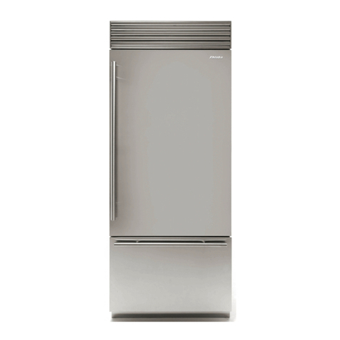
Fhiaba XS8990TST6IU User manual

Fhiaba
Fhiaba Integrated Series User manual

Fhiaba
Fhiaba Integrated Series User manual
Fhiaba
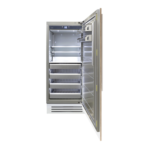
Fhiaba S8990FZ6I User manual
Fhiaba
Fhiaba 1T User manual
Fhiaba
Fhiaba 0H User manual
Fhiaba
Fhiaba S8990FR6U User manual
Fhiaba
Fhiaba 1T User manual

Fhiaba
Fhiaba 599 Series User manual
Fhiaba
Fhiaba BI30BILO User manual
