Fiberstars FDS User manual

79-15167-00 REV. A www.fiberstars.com Page 1 of 10
FDS / FDS-R / FDS-PS
USER MANUAL
3091594
ETL LISTED
Conforms to UL STD 1241
For use with 120V 60Hz input.
Output is 120V 60Hz at 5amps 600W MAX. switched.

79-15167-00 REV. A www.fiberstars.com Page 2 of 10
Basic safety precautions should be observed.
1. Ensure that incoming power is DISCONNECTED at the circuit breaker BEFORE any electrical
work is performed.
2. A qualified electrician must install the FDS in accordance with all applicable National and
Local Electrical Codes.
3. Ensure that all lights to be connected to the FDS conform to the National Electrical Code
(NEC) and all local codes and ordinances prior to connecting to the lights to the FDS.
4. Do not exceed the maximum ratings of individual components, wiring devices, and current
carrying capacity of conductors.
5. The lighting circuit must have a Ground-Fault Circuit Interrupter (GFCI), and an appropriately
rated circuit breaker.
6. The FDS must be mounted at a minimum horizontally of 48” from edge of water, 8” minimum
vertically above water level, and 4” minimum from the deck.
7. The Light fixture and all metal items within five (5) feet of the pool, including this FDS, must
be properly electrically bonded.
8. This device should never operate an equipment that could cause property damage, bodily
injury, or death should it be activated unexpectedly.
9. Never allow children to operate the FDS unsupervised.
IMPORTANT SAFETY INFORMATION
FCC WARNING
1. This device complies with Part 15 of the FCC Rules. Operation is subject to the following
two conditions: (1) this device may not cause harmful interference, and (2) this device must
accept any interference received, including interference that may cause undesired operation.
2. Changes or modifications not expressly approved by Fiberstars Inc. could void the user’s
authority to operate the equipment.

79-15167-00 REV. A www.fiberstars.com Page 3 of 10
INSTALLATION INSTRUCTIONS
The illustration below shows the components that make up the FDS. For NEW installations, all components
are supplied and utilized. For UPGRADING existing installations, the brass plate assembly below is no
t
supplied and utilized.
INDICATOR LIGHT AND LENS
NOTE: ALREADY INSTALLED
DO NOT REMOVE
FDS COVER
PRINTED CIRCUIT BOARD ASSEMBLY
FOR REMOTE OPERATION
NOTE: ALREADY INSTALLED
DO NOT REMOVE
FDS ROUND GASKET
FDS ADAPTER PLATE
FDS RECTANGULAR
GASKET
BRASS PLATE ASSEMBLY
NOTE: ONLY SUPPLIED AND
REQUIRED FOR NEW INSTALLATIONS
FDS ADAPTER SCREW
COVER MOUNTING SCREWS
ROCKER SWITCH
NOTE: ALREADY INSTALLED
DO NOT REMOVE
ROCKER SWITCH BOOT
NOTE: ALREADY INSTALLED
DO NOT REMOVE
The following pages show proper installation steps for NEW installations or UPGRADING existing
installations.

79-15167-00 REV. A www.fiberstars.com Page 4 of 10
FOR NEW INSTALLATIONS (FDS)
STEP 1. Ensure that incoming power is DISCONNECTED at the circuit breaker BEFORE any
electrical work is performed.
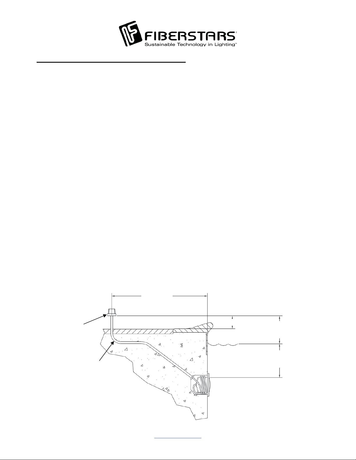
STEP 2. Place the supplied Brass base plate in accordance with National and Local electrical
codes and ordinances for junction box placement (see illustration below for proper
location and minimum spacing requirements).
STEP 3. The center conduit hub is equipped with a strain relief for a cord size of up to 10/3 AWG.
Only use with underwater lights equipped with water resistant cords.
STEP 4. Provisions for grounding terminals are provided for wires ranging from #16 AWG to #10
AWG. One equipment bonding terminal provision is provided and must be utilized for a
#8 AWG insulated copper bonding wire. Special considerations should be taken when
attaching stranded grounding and bonding conductors to the supplied grounding and
bonding screws, such as ring terminals rated for such applications.
STEP 5. Plug any unused conduit holes with the supplied conduit plugs.
STEP 6. Place the supplied rectangular gasket between the Brass base plate and the FDS adapter
(Important Note: For upgrade installations discussed on the next page, assure to replace
any existing gaskets with the supplied FDS gaskets).
STEP 7. There are three (3) wires in the FDS junction box for connection to underwater lights.
a. Connect the WHITE wire to the common from the house common and from the
common of the underwater light.
b. Connect the BLACK wire from the sub-panel connected to an appropriately rated
circuit breaker.
c. Connect the RED wire to the LOAD wire of the underwater light.
STEP 8. Place FDS cover and round gasket onto the FDS adapter and Brass base plate.
STEP 9. Using the supplied screws, finger-tighten the screws from the FDS to the Brass base
plate.
STEP 10. After all screws have been finger-tightened, completely tighten all screws in a cross
pattern so that the FDS will seal properly.
48” min.
4” min. 8” min. from bottom of J-Box
to Top of Water Line
18” min. from Water
Line to top of Lens
Rigid
Conduit
To GFCI, Circuit
Breaker, and
Power Source

79-15167-00 REV. A www.fiberstars.com Page 5 of 10
FOR UPGRADING EXISTING INSTALLATIONS (FDS-R)
STEP 1. Ensure power is DISCONNECTED at the circuit breaker before any electrical work is
done.
STEP 2. Ensure that existing Junction Box and the underwater lights to be used with the FDS meet
appropriate NEC requirements as well as local codes and ordinances.
STEP 3. Remove the Junction Box cover.
STEP 4. When upgrading from a Pentair 783106, follow “FOR NEW INSTALLATIONS”
instructions from STEP 2 to STEP 9.
STEP 5. When upgrading from a Thermocraft JBP57510, remove the FDS Adapter.
STEP 6. Place the Adapter gasket onto the Thermocraft base plate.
STEP 7. Wire the FDS according to STEP 7 in the “FOR NEW INSTALLATIONS” section.
STEP 8. Place the FDS onto the Thermocraft base plate.
STEP 9. Using the screw from the Thermocraft junction box, finger-tighten the screw FDS to the
Thermocraft base plate.
STEP 10. After all screws have been finger-tightened, completely tighten all screws in a cross
pattern so that the FDS will seal properly.
IMPORTANT:
If the FDS is used as an upgrade to an existing Junction Box, it can only be upgraded
from a Pentair Junction Box style 78310600 or a Thermocraft Junction Box style
JBP57510.
PENTAIR THERMOCRAFT

79-15167-00 REV. A www.fiberstars.com Page 6 of 10
FOR FDS-PS INSTALLATION
STEP 1. Ensure that the two FDS units are installed within the 75’ range of the remote transmitter.
STEP 2. Check the label of the FDS units to determine which operates on Circuit 1 and Circuit 2.
STEP 3. To complete the installation, follow instructions on pages 4 and 5 based on new
installation or upgrading existing installation.
Circuit 1, Channel 16 Circuit 2, Channel 16

79-15167-00 REV. A www.fiberstars.com Page 7 of 10
OPERATION INSTRUCTIONS
WIRELESS REMOTE OPERATION
The POWER ON/OFF button controls the device
connected to the Rocker Switch terminal. With
each push of the button, the FDS toggles the device
ON and OFF. Circuit control
SWITCH OPERATION
The purpose of the switch is to test and trouble shoot the FDS.
xIn the ON position, the switch bypasses the FDS and turns on the light. When in the ON
position, the Indicator Light should turn on at the same time.
xIn the OFF position, the switch shuts off power to both the FDS and the Pool Light.
xIn the Remote position, the switch allows for Remote operation with the Wireless Remote.
If none of the above operation works with the switch, please refer to the troubleshooting section of
this manual.
Indicator Light
Rocker Switch

79-15167-00 REV. A www.fiberstars.com Page 8 of 10
FDS-PS REMOTE OPERATION INSTRUCTIONS
WIRELESS REMOTE OPERATION
The POWER ON/OFF buttons control the
individual unit with the corresponding circuits
independently. With each push of the button,
the FDS-PS toggles the individual units with
corresponding circuits from ON to OFF and
vice versa. For Synchronization operation,
simply push the SYNC ON/OFF button.
N
OTE: If all circuits are off when the SYNC
ON/OFF button is pressed, all circuits will be
turned to ON. If any one of the circuits are in
the ON state by the wireless remote, then when
the SYNC ON/OFF button is pressed all
circuits will be turned OFF and the SYNC
ON/OFF must be pressed again to turn all
circuits ON simultaneously.
Circuit 1 control Circuit 2 control
For Synchronization of
Circuit 1 and Circuit 2

79-15167-00 REV. A www.fiberstars.com Page 9 of 10
CODE ADJUSTMENT
It may be necessary to change the transmission code on the FDS Transmitter to match that of the FDS unit. Chec
k
the FDS product label on the outside to see if the CHANNEL marking is the same as the transmitter. If they do no
t
match, then follow the instructions below.
TRANSMITTER DIP SWITCHES – Remove all screws from rear of remote. Separate the bottom cover from the
top cover. Take care as to not damage or lose the Rubber seal when separating the bottom cover.
DIP SWITCH ADJUSTMENT – The four DIP switches have an ON and an OFF position. Changing just one DIP
switch will change the code. Change the DIP switches in reference to the Channel Code to match that of the FDS.
Reassemble the bottom cover to the top cover carefully. Ensure that the bottom cover seats onto the top cover.
Screw down the mounting screws until they are snug. Over tightening the screws may damage internal threading
and may cause transmitter bottom not to seal properly. The example below shows DIP switch set to Channel 9.
DIPSWITCH1234
Channel 1 OFF OFF OFF OFF
Channel 2 ON OFF OFF OFF
Channel 3 OFF ON OFF OFF
Channel 4 ON ON OFF OFF
Channel 5 OFF OFF ON OFF
Channel 6 ON OFF ON OFF
Channel 7 OFF ON ON OFF
Channel8ONONONOFF
Channel 9 OFF OFF OFF ON
Channel 10 ON OFF OFF ON
Channel 11 OFF ON OFF ON
Channel 12 ON ON OFF ON
Channel 13 OFF OFF ON ON
Channel 14 ON OFF ON ON
Channel 15 OFF ON ON ON
Channel 16 ON ON ON ON
DIP Switch
Rear screws
Rubber seal
CHANNEL
DIP Switch
NOTE: Transmitters are factory set and
shipped on channel 16.

79-15167-00 REV. A www.fiberstars.com Page 10 of 10
TROUBLESHOOTING
REMOTE POSITION STEP
Pool Light does not turn ON 1) Make sure Rocker Switch is in the REMOTE position.
2) Try button on Remote Control again.
Pool Light Does not come on but
indicator light does.
3) If pool light still does not come ON but indicator light
does – Pool light is bad. If indicator light fails to come
on – go to STEP 4
MANUAL-ON-POSITION
Pool light comes ON 4) Move Rocker switch to ON position. If pool light
comes on, FDS or Remote Control is the problem.
4a) Replace batteries on Remote Control
4b) Verify code on outside of FDS and inside of
Remote Control.
REDO STEPS 1 & 2 if pool light again fails to come ON
or have a qualified electrician replace FDS unit.
MANUAL-ON-POSITION
Pool light does not come ON and
indicator light does not come ON.
1) Test GFCI – RESET
2) Problem with electrical service. Call a qualified
electrician for service work.
This manual suits for next models
2
Table of contents
Other Fiberstars Lighting Equipment manuals
Popular Lighting Equipment manuals by other brands

Kind LED Grow Lights
Kind LED Grow Lights X2 user manual

Pure Reliability
Pure Reliability PANDA II PR-2100B product manual

American DJ
American DJ Color 250D User instructions

AC Infinity
AC Infinity IONBEAM user manual

PROEL
PROEL PLLEDSPAR12 user manual

Federal Signal Corporation
Federal Signal Corporation Navigator Lightbar Installation, operation and service instructions