FIC 1st Mainboard KC19+ User manual

KC19+
MAINBOARD
MANUAL
DOC No.: M99701
Rev. : A1
Date : 3, 2000
Part No. : 25-11412-21

Handling Precautions
Warning:
1. Static electricity may cause damage to the integrated circuits on
the mainboard. Before handling any motherboard outside of its
protective packaging, ensure that your body is not electrostatically
charged.
2. There is a danger of explosion if the battery is incorrectly replaced.
Replace only with the same or an equivalent type of battery as
recommended by the manufacturer.
3. Discard used batteries according to the manufacturer’s
instructions.
Observe the following basic precautions when handling the motherboard
or other computer components:
nWear a static wrist strap which fits around your wrist and is
connected to a natural earth ground.
nTouch a grounded or anti-static surface or a metal fixture such as a
water pipe.
nEnsure add-on cards, mainboards, and models do not come into
contact with the golden fingers connectors, plugged into the expan-
sion slot.
The above methods prevent static build-up and allow it to be discharged
properly.
Trademark
All trademarks mentioned in this manual are registered property of
the respective owners.
Handling Precautions
This manual may not, in whole or in part, be photocopied, reproduced,
transcribed, translated, or transmitted in whatever form without the
written consent of the manufacturer, except for copies retained by the
purchaser for personal archival purposes.
Notice

i
TableofContents
Table of Contents
Chapter 1 Overview
The KC19+ Mainboard .............................................................. 1-2
Package Checklist .......................................................................... 1-2
Main Features ................................................................................ 1-3
ACPI Ready ................................................................................... 1-5
FIC Unique Innovation for Users (NOVUS) -
Enhanced Mainboard Features and System Support .................... 1-5
Chapter 2 Installation Procedures
Quick Reference ............................................................................. 2-2
Mainboard Layout ......................................................................... 2-6
1). Set System Switches ................................................................ 2-8
Clear CMOS: SW1-2 .......................................................... 2-8
Clear Password: SW1-3 ..................................................... 2-8
2). Install Memory Modules .......................................................... 2-9
RAM Module Configuration ..................................................... 2-9
Install and Remove RIMMs ...................................................... 2-9
3). Install the CPU .......................................................................... 2-10
CPU Frequency Selection .......................................................... 2-12
4). Install Expansion Cards ............................................................. 2-13
5). Connect Devices ....................................................................... 2-14
Floppy Diskette Drive Connector: Floppy ........................ 2-14
IDE HDD Device Connectors: Primarey, Secondary .......... 2-15
ATX Power Connector: POWER ....................................... 2-15
CPU Fan Connector: CPU_FAN ........................................ 2-16
Wake-On-LAN Connector: WOL ...................................... 2-16
Front Panel Block Connector: STATUS_PANEL ............... 2-17
PS/2 Keyboard and Mouse Connector: KB, MS ............... 2-18
Universal Serial Bus Connectors: USB .............................. 2-18
Printer Connector: LPT ...................................................... 2-19
Serial Port Connectors: COM1, COM2 .............................. 2-19
Chapter 3 BIOS Setup

ii
KC19+Mainboard Manual
Chapter 4 FAQs
General FAQs ................................................................................. 4-1
BIOS FAQs .................................................................................... 4-4
Windows 98/98 SE FAQs ............................................................... 4-6
Windows 95 FAQs ......................................................................... 4-6

1 - 1
Overview
Overview
Chapter 1
The new 1stMainboard KC19+ is an ATX sized Slot 1 motherboard supporting
the latest high speed Intel® Pentium® III 450 733 MHz and Pentium® II 350
450 MHz processors at FSB speeds of 100/133 MHz. With 2 RIMM there is
support for up to 1GB of the new industry changing memory technology
Rambus DRAM.
The KC19+ is based around the new Intel 820 Chipset which delivers a new
level of superior performance and headroom with next generation RDRAM
memory, while also being equipped with ECC memory support. The enhanced
performance of AGP 4X graphics technology provides 1GB/s bandwidth, eas-
ily supporting new games and upcoming 3D-hardware.
The new HUB Architecture replaces the slow PCI bus (133MB/s) and relieves
the previous bottleneck to I/O devices by doubling the bandwidth to 266MB/
s. Support for the Ultra DMA/66 protocol and its high-speed interface further
ensures that data transfer speeds are improved, especially for long sequential
transfers required by audio/visual applications. The Intel 820 provides excep-
tional onboard audio and video capabilities reducing potential costs for sys-
tem integrators by eliminating the cost of purchasing and assembling Audio/
VGA cards.
Expansion is provided by 1 AGP, 4 PCI and 2 ISA slots. Standard I/O connec-
tions include 2 serial ports, 1 parallel port, 1 PS/2 mouse and keyboard connec-
tor, 2 USB connectors and 1 media connector ( Line-in, Line-out and Mic-in).
The KC19+ is fully PC99 and Y2K compliant, and is ACPI ready, ensuring
improved energy efficiency. Other features include hardware monitoring, Wake-
On-LAN, CD Pro with enhanced drivers.

1 - 2
KC19+Mainboard Manual
The KC19+ Mainboard
Package Checklist
If you discover any item below was damaged or lost, please contact your
vendor.
Ö The mainboardwithoneC-RIMMmodule
Ö Thisusermanual
Ö Onefloppydisk drivecable
Ö One HDD cable
Ö OneATA-66 cable
Ö CD-ProSoftwareutilities
Ö CD Plus Software tools

1 - 3
Overview
Main Features
■Easy Installation
||BIOS with support for Plug and Play, auto detection of IDE hard drives,
||LS-120|drives, IDE ZIP drives, Windows 95, Windows 98/98 SE, Windows
||2000, and OS/2.
■Leading Edge Chipset
Intel 820 chipset provide integrated memory controllers with new Dy-
namic Power Management Architecture (DPMA), concurrent PCI (2.0/
2.1), AGP 1.0 compliant and USB.
■Flexible Processor Support
Onboard CPU Slot supports:
Intel® Pentium® III 450-733+ MHz at 100/133 Front Side Bus
Intel Pentium® II 350-450 MHz at 100 Front Side Bus.
|■Versatile Main Memory Support
Accepts up to 1 GB RDRAM using two Direct RIMMs of 64, 128, 256,
512MB with support for lightning-fast RDRAM (800MHz).
■Enhanced PCI Bus Master IDE Controller with Ultra DMA/33 and
Ultra DMA/66 Support
Integrated Enhanced PCI Bus Master IDE controller features two dual-
channel connectors that accept up to four Enhanced IDE devices, includ-
ing CD-ROM and Tape Backup Drives, as well as Hard Disk Drives sup-
porting the new Ultra DMA/66 protocol. Standard PIO Mode 3, PIO Mode
4, DMA Mode 2, DMA Mode 4 devices are also supported.
■AGP, ISA, and PCI Expansion Slots
One AGP Bus expansion slot, four PCI Bus expansion slots, and two ISA
Bus provide the room to install a full range of add-on cards.

1 - 4
KC19+Mainboard Manual
■■
■■
■Super Multi Input/Output (I/O) Support
Integrated Plug and Play multi-I/O chipset features two high-speed UART
16550 compatible serial ports, one EPP/ECP capable parallel port, and one
FDD connector.
■■
■■
■Convenient Rear Panel USB Connection Support
Two USB ports integrated in the rear I/O panel with one manufacturing
optional USB connector for front panel connection allow convenient and
high-speed Plug and Play connections to the growing number of USB
compliant peripheral devices on the market.
■■
■■
■Remote Wake On LAN Support
Onboard Wake On LAN (WOL) connector allows remote management on
your network even when the system is powered off. The feature provides
a more simple and convenient control for LAN-based networks.
■■
■■
■Onboard Accelerated Graphics Port (AGP)
The motherboard is installed with one 32-bit AGP bus with a dedicated
66MHz/133MHz path from the graphics card to the system memory (in 4x
mode), offering much greater bandwidth than the 32-bit PCI bus. The
board is fully compliant with the AGP 1.0 specification. AGP enabled 3D
graphics cards can directly access main memory across this fast path
instead of using local memory. To make use of the improved AGP perfor-
mance, the motherboard should be installed with SDRAM type memory
and the VGA card Drivers should also be fully AGP compliant. Using
Microsofts Windows 98/SE and Windows 2000 which implement
DirectDraw will allow the system to take full use of AGPs benefits with-
out the need to install additional drivers.

1 - 5
Overview
ACPI Ready
This mainboard fully implements the new ACPI (Advanced Configuration and
Power Interface) 1.0 Hardware and BIOS requirement. If you install a ACPI
aware operating system, such as Windows 98/98 SE, you can fully utilize the
power saving features under ACPI.
The mainboard is compatible with all other non ACPI-aware operating sys-
tems. If you want to setup ACPI features under Windows 98, please follow the
instructions below:
Run Windows 98 setup by using setup/p j on the command line for installing
Windows 98 with the ACPI control features.
If you type setup without the parameter /p j, Windows 98 will be installed as
APM, PnP mode, no ACPI will be used.
For more detailed information, please visit the web site of Microsoft. The URL
is : www.microsoft.com/hwtest/.
FIC Unique Innovation for Users (NOVUS) -
Enhanced Mainboard Features and System Support
NOTE: If BIOS date is after 12/02/1999, the ACPI will be installed
automatically. Users do not need to setup in the above-mentioned
way.
■■
■■
■BIOS Guardian
BIOS Guardian by default is enabled. It must be disabled in order to
reflash BIOS, thus effectively acting as a fire-wall against viruses that can
attack the BIOS while the system is running.
BIOS Guardian can be disabled as follows:
1. Go to BIOS Set Up Menu.
2. Disable BIOS Guardian.
3. Save the setting, and restart system.

1 - 6
KC19+Mainboard Manual
This Page Left Blank for Notes

2 - 1
Installation Procedures
Chapter 2
Installation Procedures
The KC19+ has several user-adjustable jumpers on the board that allow you to config-
ure your system to suit your requirements. This chapter contains information on the
various jumper settings on your mainboard.
To set up your computer, you must complete the following steps:
■ Step 1 - Set system switches
■ Step 2 - Install system memory modules
■ Step 3 - Install the Central Processing Unit (CPU)
■ Step 4 - Install expansion cards
■ Step 5 - Connect ribbon cables, cabinet wires, and power supply
■ Step 6 - Set up BIOS software (see Chapter Three)
■ Step 7 - Set up supporting software tools
WARNING: Excessive torque may damage the mainboard. When
using an electric screwdriver on the mainboard, make sure that
the torque is set to the allowable range of 5.0 ~ 8.0kg/cm.
Mainboard components contain very delicate Integrated Circuit
(IC) chips. To prevent static electricity from harming any of the
mainboard’s sensitive components, you should follow the
following precautions whenever working on the computer:
1. Unplug the computer when working on the inside.
2. Hold components by the edges and try not to touch the IC
||||chips, leads, or circuitry.
3. Wear an anti-static wrist strap which fits around the wrist.
4. Place components on a grounded anti-static pad or on the bag
that came with the component whenever the components are
separated from the system.

2 - 2
KC19+Mainboard Manual
This Chapter is intended to aid quick and easy installation.
In the event that more detailed information is required,
please consult the Installation Procedures Chapter.

2 - 3
Installation Procedures
2 - 4
KC19+Mainboard Manual
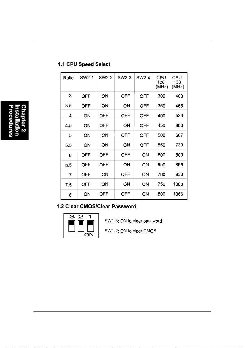
1). CPU Speed Select, Clear CMOS, Clear
Password
2). CPU Fan Installation
This connector is linked to the CPU fan. When the system is in suspend mode, the
CPU fan will turn off; when it reverts back to full on mode, the fan will turn back on.
Without sufficient air circulation, the CPU may overheat resulting in damage
to both the CPU and the mainboard.
Damage may occur to the mainboard and/or the CPU fan if these pins are
used incorrectly. These are not jumpers, do not place jumper caps over these
pins.

2 - 5
Installation Procedures
3). Front Panel Block
Cable Connection
4). Load Setup Defaults
Load default values for all SETUP items or press F9 key to setup defaults.
5). How to Upgrade BIOS
1. Format a bootable system floppy diskette by typing the command format
a:/s in command mode.
2. Visit the the web site of the vendor and visit the BIOS Update page in the
related Technical Support section.
3. Select the BIOS file you need and download it to your bootable floppy
diskette.
4. Insert the bootable diskette containing the BIOS file into the floppy dis-
kette drive.
5. Assuming that the floppy diskette drive is A, reboot the system by using
the A: drive. At the A: > prompt, run the BIOS upgraded file by executing
the Flash BIOS utility and the BIOS file with its appropriate extension.
Do not turn off or reset the computer during the flash process or there will be
a problem booting up your system.
The files Phlash.exe, Platform.bin, and ROM file should be placed in the
same directory.
Command: {flash tool file Phlash.exe}{space}{downloaded BIOS file,
ROM file} <Enter>
WARNING: Please disable the BIOS feature that related to BIOS
Guardian before you start to reflash BIOS.

2 - 6
KC19+Mainboard Manual
Mainboard Layout

2 - 7
Installation Procedures
ONBOARDMARK MEANING PAGE
Jumpers
SW1-3 Clear CMOS Data 2 - 8
SW1-2 Clear Password 2 - 8
SW2-1/2/3/4 CPU Frequency Select 2 - 12
Slots
RIMM1/2 RIMM Memory Module Support 2 - 9
SLOT1 CPU Cartridge Slot 2 - 10
PCI1/2/3/4 PCI Bus Expansion Slot 2 - 13
ISA1/2 ISA Bus Expansion Slot 2 - 13
AGP AGP Bus Expansion Slot 2 - 13
Connectors
FLOPPY Floppy Diskette Drive Connector 2 - 14
PRIMARY, SECONDARY IDE HDD Device Connectors 2 - 15
POWER ATX Power Connector 2 - 15
CPU_FAN CPU Fan Connector 2 - 16
WOL Wake on LAN Connector 2 - 16
STATUS_PANEL Connectors for Front Panel LEDs
and Switches on Front Panel 2 - 17
KB, MS PS/2 Keyboard and Mouse Connector 2 - 18
USB Universal Serial Bus Connectors 2 - 18
LPT Printer Connector 2 - 19
COM1/2 Serial Port Connector 2 - 19
2 - 8
KC19+Mainboard Manual
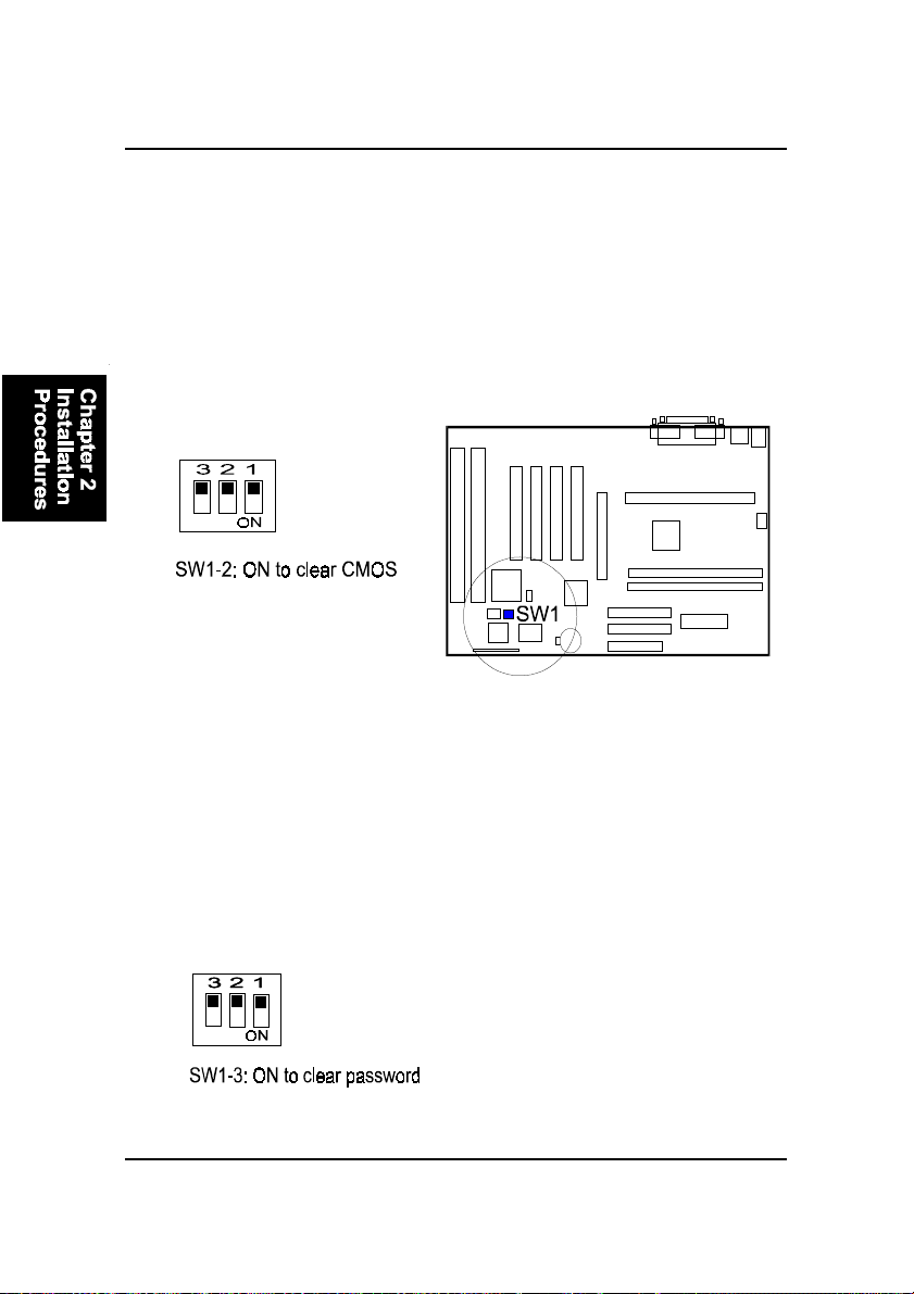
Clear Password: SW1-3
This switch allows you to enable or disable the password configuration. You
may need to enable this switch by moving it to the On (Enabled) position if
you forget your password. To clear the password setting: (1) Turn off your
computer, (2) Move the Clear Password switch SW1-6 to On (Enabled), (3)
Turn on your computer, (4) Hold down the Delete key during bootup and enter
BIOS Setup to re-enter user preferences, (5) Turn off your computer, (6) Move
the Clear Password switch SW1-6 to Off (Disabled), (7) Turn on your com-
puter for the new settings to take effect.
1). Set System Switches
Clear CMOS: SW1-2
The CMOS RAM is powered by the onboard button cell battery. To clear the
RTC data: (1) Turn off your computer. (2) Move the CMOS Clear switch SW1-
5 to On (Enabled). (3) Turn on your computer to display CMOS checksum
error. (4) Turn off your computer. (5) Move the CMOS Clear switch SW1-5 to
Off (Disabled). (6) Turn on your computer. (7) Hold down the Delete key
while booting. (8) Enter the BIOS Setup to re-enter user preferences.

2 - 9
Installation Procedures
2). Install Memory Modules
RAM Module Configuration
This mainboard provides two onboard RIMM sockets to support Direct
RAMBUS (RDAM) modules. Either 64, 128, 256, 512 MB DIMM can be in-
stalled on these two sockets. If one DIMM socket leaves empty, it must have
a C-RIMM module on it. (The C-RIMM module comes with this board.) The
maximum total memory supported is up to 1 GB.
Install and Remove RIMMs
1. Locate the RIMM slots on the mainboard.
2. Install the RIMM straight down into the RIMM slot using both hands.
3. The clip on both ends of the RIMM slot will close up to hold the RIMM
in place when the RIMM reaches the slots bottom.

2 - 10
KC19+Mainboard Manual
CAUTION:
1. Always turn the system power off before installing or removing
any device.
2. Always observe static electricity precautions. See “Handling Pre-
cautions” at the start of this manual.
3. Inserting the chip incorrectly may damage the chip.
1. Locate SLOT1 on the mainboard.
2. Pull out two columns of the Retention Mechanism Assembly upward to
the right position.
3. Insert the CPU module downward along with the columns of the Reten-
tion Mechanism Assembly until it is inserted the SLOT1 firmly.
3). Install the CPU
The CPU module resides in the SLOT1 on the motherboard. The Retention
Mechanism Assembly that is foldable for saving space when shipping and
packing had been installed on the board by the manufacturer. Please follow
the steps introduced below to complete the CPU installation.
Table of contents
Other FIC Motherboard manuals


