FIC VT-502 User manual

VT-502
MAINBOARD
MANUAL
DOC No. : 1604
9
Rev. : A0
Date : 8, 1997
Part No. :
25
-
10809
-
00

Handling Precautions
Warning :
1. Static electricity may cause damage to the integrated circuits on the
mainboard.
Before handling any mainboard outside of its protective packaging,
ensure that there is no static electric charge in your body.
2. There is a danger of explosion if the battery is incorrectly replaced.
Replace only with the same or an equivalent type recommended by the
manufacturer.
3. Discard used batteries according to the manufacturer’s instructions.
Observe the following basic precautions when handling the mainboard or
other computer components:
Wear a static wrist strap which fits around your wrist and is connected to a
natural earth ground.
Touch a grounded or anti-static surface or a metal fixture such as a water
pipe.
Avoid contacting the components on add-on cards, boards and modules and
with the “gold finger” connectors plugged into the expansion slot. It is best
to handle system components by their mounting bracket.
The above methods prevent static build-up and cause it to be discharged
properly.
Trademark
All trademarks mentioned in this manual are registered properly of the
respective owners.
Copyright
This manual may not, in whole or in part, be photocopied, reproduced,
transcribed, translated, or transmitted in whatsoever form without the
written consent of the manufacturer, except for copies retained by the
purchaser for personal archival purposes.
Notice

i
Chapter 1 Overview
Package Checklist ....................................................................................... 2
The VT-502 Mainboard .............................................................................. 3
Main Features ............................................................................................. 4
Something Interesting ................................................................................. 6
The BIOS Setup Utility ..................................................................... 6
IRQ Functionality .............................................................................. 6
DMA Channels of ISA Cards ............................................................ 7
Enhanced IDE ................................................................................... 7
Serial Infrared (SIR) Connections ..................................................... 8
Universal Serial Bus (USB) Functionality ........................................ 8
Chapter 2 Installation Procedures
Mainboard Layout ...................................................................................... 10
1). Set System Jumpers ............................................................................... 11
Jumpers ............................................................................................. 11
Clear Password: CPW ............................................................... 12
Flash EPROM Type Selection: EP1, EP2 ................................. 12
2). Install System RAM Modules ............................................................... 13
DRAM and SDRAM ......................................................................... 13
RAM Module Configuration ............................................................. 14
Install SIMMs.................................................................................... 15
Remove SIMMs ................................................................................ 15
Install DIMMs ................................................................................... 16
Remove DIMMs ................................................................................ 16
Cache Memory .................................................................................. 17
3). Install the CPU ...................................................................................... 18
CPU External Clock (Bus) Frequency: CLK1, CLK2, CLK3 ... 19
CPU to Bus Frequency Ratio: FREQ1, FREQ2, FREQ3 .......... 19
Intel Pentium/Pentium MMX CPUs .......................................... 20
Frequency ............................................................................. 20
Voltage ................................................................................. 21
AMD-K5/K6 CPUs ................................................................... 22
Frequency ............................................................................. 22
Voltage ................................................................................. 23
Cyrix 6x86/6x86MX CPUs ....................................................... 24
Frequency ............................................................................. 24
Voltage ................................................................................. 25
IBM 6x86/6x86MX CPUs ......................................................... 26
Frequency ............................................................................. 26
Voltage ................................................................................. 27
4). Install Expansion Cards ......................................................................... 28
Table of Contents

VT-502 Mainboard Manual
ii
5). Connector Cables and Power Supply .................................................... 30
Serial Port Connectors: COM1, COM2 ..................................... 30
CPU Fan Connector: FAN......................................................... 30
Floppy Diskette Drive Connector: FLOPPY ............................. 31
Infrared Connector: IR .............................................................. 31
Front Panel Block Connector: F_PNL ....................................... 32
Standard Power Connector: POWER ........................................ 33
IDE HDD Device Connectors: PRIMARY, SECONDARY ..... 34
PS/2 Mouse Connector: MS_CON ............................................ 34
Remote Power Supply Connector: RPW_CON ......................... 35
AT Keyboard Connector: AT_KB ............................................ 35
Printer Connector: PRINTER .................................................... 36
Universal Serial Bus Connectors: USB1, USB2........................ 36
Chapter 3 Award BIOS Setup
CMOS Setup Utility ................................................................................... 37
Standard CMOS Setup ................................................................................ 38
Hard Disk Configurations ................................................................. 38
BIOS Features Setup ................................................................................... 40
Chipset Features Setup ............................................................................... 43
Power Management Setup .......................................................................... 46
PNP Configuration Setup............................................................................ 48
Load BIOS Defaults ................................................................................... 50
Load Setup Defaults ................................................................................... 50
Integrated Peripherals ................................................................................. 51
Supervisor/User Password .......................................................................... 54
IDE HDD Auto Detection ........................................................................... 55
Save and Exit Setup .................................................................................... 56
Exit without Saving .................................................................................... 56
Appendix A BIOS Update Instruction
Flash Process .............................................................................................. 57
Appendix B Software Utilities
DMI Utility ................................................................................................. 59
Starting DMI Utility .......................................................................... 59
IDE Utility .................................................................................................. 60

1
Overview
The VT-502 mainboard combines the advanced capabilities of the Intel
82430VX PCIset with a 321-pin ZIF socket and voltage regulator which
supports the full range of Intel Pentium® processors, including the Intel
Pentium® processor with MMX™ technology as well as AMD-K5/K6 and
Cyrix/IBM 6x86™/6x86MX™ processors to provide the ideal platform for
building the high performance Microsoft Windows™ multimedia systems.
The VT-502 achieves the highest level of system responsiveness using up to
128 MB high-speed EDO DRAM or 128MB lightning-fast SDRAM coupled
with an onboard 512KB/256KB Pipeline Burst SRAM Level 2 cache.
Built on the highly concise Baby AT form factor, the VT-502 integrates a full
set of I/O features onboard, including two 16550A UART compatible serial
ports, one EPP/ECP capable parallel port and support for state-of-the-art
Universal Serial Bus (USB) through the optional USB riser card providing
ease-of-use and high-speed Plug & Play connections to future USB
complaint peripheral devices. System I/O connectivity is further enhanced
by an IrDA complaint serial port, an optional PS/2 Keyboard & PS/2 Mouse
port and onboard SIR support.
Ample expansion is provided for with three 16-bit ISA slots and four 32-bit
PCI slots. The VT-502 also comes with a built-in Enhanced PCI Bus Master
PCI IDE controller that provides high speed connections to a full range of
IDE devices including HDD, CD-ROM and Tape-Drives, and delivers ultra
fast data transfer up to 20MB/sec through its support for PIO Mode3,
Mode4 and DMA Mode 2.
This chapter gives a you a brief overview of the VT-502 mainboard. In
addition to basic information on the board's main components and features,
it also provides advice on how to upgrade and expand it. For updated BIOS,
drivers, or product release information, please visit FIC's home page at:
http://www.fic.com.tw. Congratulations on your decision to adopt the VT-
502 mainboard. With its high-speed PCI local bus architecture and ultra-fast
I/O connections, the VT-502 provides the ultimate solution for optimizing
the performance of your high-end system.
Chapter 1

VT-502 Mainboard Manual
2
Package Checklist
Please check that your package contains all the items listed below. If you
discover any item is damaged or missing, please contact your vendor.
The VT-502 mainboard
This user manual
One IDE HDD cable
One floppy disk drive cable
One printer and COM1 cable
One COM2 cable
One USB riser card (optional)
Software utility

Overview
3
The VT-502 Mainboard

VT-502 Mainboard Manual
4
Main Features
The VT-502 mainboard comes with the following high-performance
features:
Easy Installation
Award BIOS with support for Plug and Play, auto detection of Hard Drive,
LS-120 drives, and IDE features, MS Windows 95.
Flexible Processor Support
Onboard 321-pin ZIF socket support complete range of leading-edge
processors:
Intel Pentium Pentium MMX technology P55C 166/200/233 MHz
processors.
Intel Pentium Pentium
P54C/P54CS/90/100/120/133/150/166/200 MHz processors.
||||||||AMD-K6-166 (166 MHz) / K6-200 (200 MHz) processors.
|||||||||AMD-K5- PR90 (90 MHz) / K5-PR100 (100 MHz) / K5-PR120 (90
|||||||||MHz) / K5-PR133 (100 MHz) / K5-PR150 (105 MHz) / K5-PR166
(116 |||||||||MHz) / K5-PR200 (133 MHz) processors.
Cyrix 6x86MX- PR166 (150 MHz) / 6x86MX-PR200 (166 MHz)
|||||||||processors. Please read page 24 for details.
|| || | Cyrix 6x86- PR133+ (110 MHz) / 6x86-PR150+ (120 MHz) / 6x86-
|||||||||PR166+ (133 MHz) processors.
IBM 6x86MX- PR166 (150 MHz) / 6x86MX-PR200 (166 MHz)
||||||||processors. Please read page 26 for more information.
| IBM 6x86- PR133+ (110 MHz) / 6x86-PR150+ (120 MHz) / 6x86-
||||||||PR166+ (133 MHz) processors.
Various External Bus and CPU/Bus Frequency Ratio Support
The mainboard supports the Bus frequency of 55 / 60 / 66MHz and the
CPU/Bus frequency ratio of 1x / 1.5x / 1.75x / 2x / 2.5x / 3x / 3.5x / 4x.
|||||||||(Please refer to Sec. Install the CPU in Chapter 2 for more
information).

Overview
5
Leading Edge Chipset
Intel 82430VX chipset, including a CPU interface controller, advanced
cache controller, integrated DRAM controller, synchronous ISA bus
controller, PCI local bus interface, integrated power management unit.
Ultra-fast Level II Cache
Supports onboard 512KB/256KB synchronous PBSRAM direct-mapped
write-back cache memory.
Versatile Main Memory Support
Accepts up to 128MB RAM in two banks using 72-pin SIMMs of 4, 8, 16,
32MB or using two 168-pin DIMM with support for SDRAM or EDO
memory.
ISA & PCI Expansion Slots
Three 16-bit ISA and four 32-bit PCI expansion slots provide all the room
you need to install a full range of add-on cards.
USB Support
Two USB ports on an optional riser card allow convenient, high-speed Plug
|||||||||and Play connections to the growing number of USB compliant external
|||||||||peripheral devices on the market.
Enhanced PCI Bus Master IDE Controller
Integrated Enhanced PCI local bus IDE controller with two connectors
supports up to four IDE devices such as Hard Disk, CD-ROM or Tape
Backup drives via two channels for high speed data throughput. This
controller supports PIO Modes 3 and 4, and DMA Mode 2 for optimized
system performance.
Super Multi I/O
Integrated SMC FDC37C669 / LG Prime 3C Super I/O chipset features two
|||||||||16550A UART compatible serial ports, one EPP/ECP capable parallel port,
|||||||||one IR port, and one Floppy Disk Drive connector.

VT-502 Mainboard Manual
6
Something Interesting
This section provides useful information that you will need to know should
you decide to modify or upgrade the configuration of the mainboard and
the system it is installed in. If you do not have the confidence to upgrade the
mainboard yourself, we advise that you consult a qualified service
technician for assistance.
The BIOS Setup Utility
The BIOS (Basic Input Output System) is the basic firmware that instructs
the computer how to operate. For the BIOS to work properly, there must be
a record of the computer's hardware and configuration settings for it to
refer to. This record is created using the Setup Utility, a program that is
stored permanently in the BIOS ROM chip on the mainboard.
The system configuration record created by the Setup Utility is also stored
on the mainboard, but not permanently. This section of the memory it is
stored is in the NVRAM. When you buy your computer, the system
configuration record will already be set and may in some cases differ from
the basic defaults. The first time you use your computer or when you need
to re-configure your system, you should run the Setup Utility and write
down the settings.
IRQ Functionality
As you read through this manual, you will see the term IRQ on a number of
occasions. It is important for you to know what this term means,
particularly if you intend to upgrade your system.
IRQ stands for Interrupt Request, the process in which an input or output
device tells the processor to temporarily interrupt its current task and
immediately process something from the source of the interrupt. When it
has completed this, the processor returns to the task it was already
processing. Devices that need an
IRQ line to operate sometimes need to have exclusive use of that line.
A large number of add-on cards, such as sound cards and LAN cards,
require the use of an IRQ line to function. Some no. of IRQs may already be
in use by components in the system such as the keyboard and mouse. Add-
on cards that need to use an IRQ draw from the unused group of IRQs.
When installing a card that uses an IRQ, it will have a default IRQ setting

Overview
7
which you might have to change if that IRQ is already in use and cannot be
shared.
Both ISA and PCI add-on cards may need to use IRQs. System IRQs are
available to add-on cards installed on the ISA bus first; the remaining ones
can be used by cards installed on the PCI bus. There are two categories of
ISA add-on cards: so-called Legacy ISA cards, which need to be configured
manually and then installed in any available ISA slot; and Plug and Play
(PnP) ISA cards, which are configured automatically by the system. As a
result, when you install Legacy ISA cards, you have to carefully configure
the system to ensure that the installed cards do not conflict with each other
by having the same IRQ. With PnP cards, on the other hand, IRQs are
assigned automatically from the ones available in the system. In the case of
PCI add-on cards, the BIOS automatically assigns an IRQ card to the PCI slot
the card is installed in.
DMA Channels of ISA Cards
Some Legacy and PnP ISA add-on cards may also need to use a Direct
Memory Access (DMA) channel. DMA assignments for this mainboard are
handled in the same way as the IRQ assignment process outlined above. For
more information, please refer to Chapter 3 of this manual.
Enhanced IDE
This mainboard features an integrated Enhanced IDE controller that
provides convenient, high-speed connections with up to four IDE devices,
such as Hard Disk, CD-ROM and Tape Backup Drives. Enhanced IDE is an
upgrade of the original IDE specification and provides increased capabilities
and performance in a number of areas, including support for Hard Disk
Drives of over 1.2GB and faster data transfer rates utilizing the PIO Mode 4
timing scheme.
With the integrated IDE controller you can connect up to four IDE
peripheral devices to your system. All devices are categorized in the same
way that IDE Hard Disks were configured in the past, with one device set as
the Master device and the other as the Slave device. We recommend that
Hard Disk Drives use the Primary IDE connector and that CD-ROM drives
utilize the Secondary IDE connector for improved system performance.

VT-502 Mainboard Manual
8
Serial Infrared (SIR) Connections
This mainboard features support for highly-sophisticated SIR technology,
which allows bi-directional and cordless data transactions with other IrDA
compliant computers and peripheral devices using infrared as a medium.
This transmission is carried out in either Full Duplex Mode or Half Duplex
Mode. The former allows simultaneous data transmission and reception,
while the latter disables the reception when transmission occurs.
The I/O chipset on this mainboard features a SIR interface that is fully
compliant with the IrDA standard. An IrDA device can be installed via a 9-
pin D-SUB connector in the rear panel of the computer which is linked by a
cable to the onboard IrDA pinhead.
The serial port COM2 on this mainboard is designed to be an SIR compliant
port. If you wish to install the SIR connection feature, you need to adjust the
BIOS option for high-speed performance.
Universal Serial Bus (USB) Functionality
USB overcomes conventional I/O bottlenecks by combining the I/O ports
into a single dual-channel connector. For optimum ease of use and
flexibility, USB not only allows the automatic detection and configuration of
peripherals after installation, but also enables the simultaneous connection.
This mainboard features an optional USB riser card (see the photo below)
with bracket that can be installed in one of the I/O expansion slots on the
rear panel of the system, as shown in the illustration below. It provides fast
and convenient Plug and Play peripheral connections outside your
computer, allowing you take full advantage of the universal functionality
and flexibility of USB technology.

9
Installation Procedures
The VT-502 has several user-adjustable jumpers on the board that allow
you to configure your system to suit your requirements. This chapter
contains information on the various jumper settings on your mainboard.
To set up your computer, you should follow these installation steps:
Step 1 -
Set system jumpers
Step 2 -
Install System RAM modules
Step 3 -
| Install the CPU
Step 4 -
| Install expansion cards
Step 5 -
| Connect cables and power supply
Step 6 -
| |Set up BIOS feature (Please read Chapter Three.)
CAUTION : If you use an electric drill to install this mainboard on your
chassis, please wear a static wrist strap. The recommended electric drill
torque is from 5.0 to 8.0 kg/cm to avoid damaging the chips’ pins.
Chapter 2

VT-502 Mainboard Manual
10
Mainboard Layout
Installation Procedures
11
1). Set System Jumpers
Jumpers
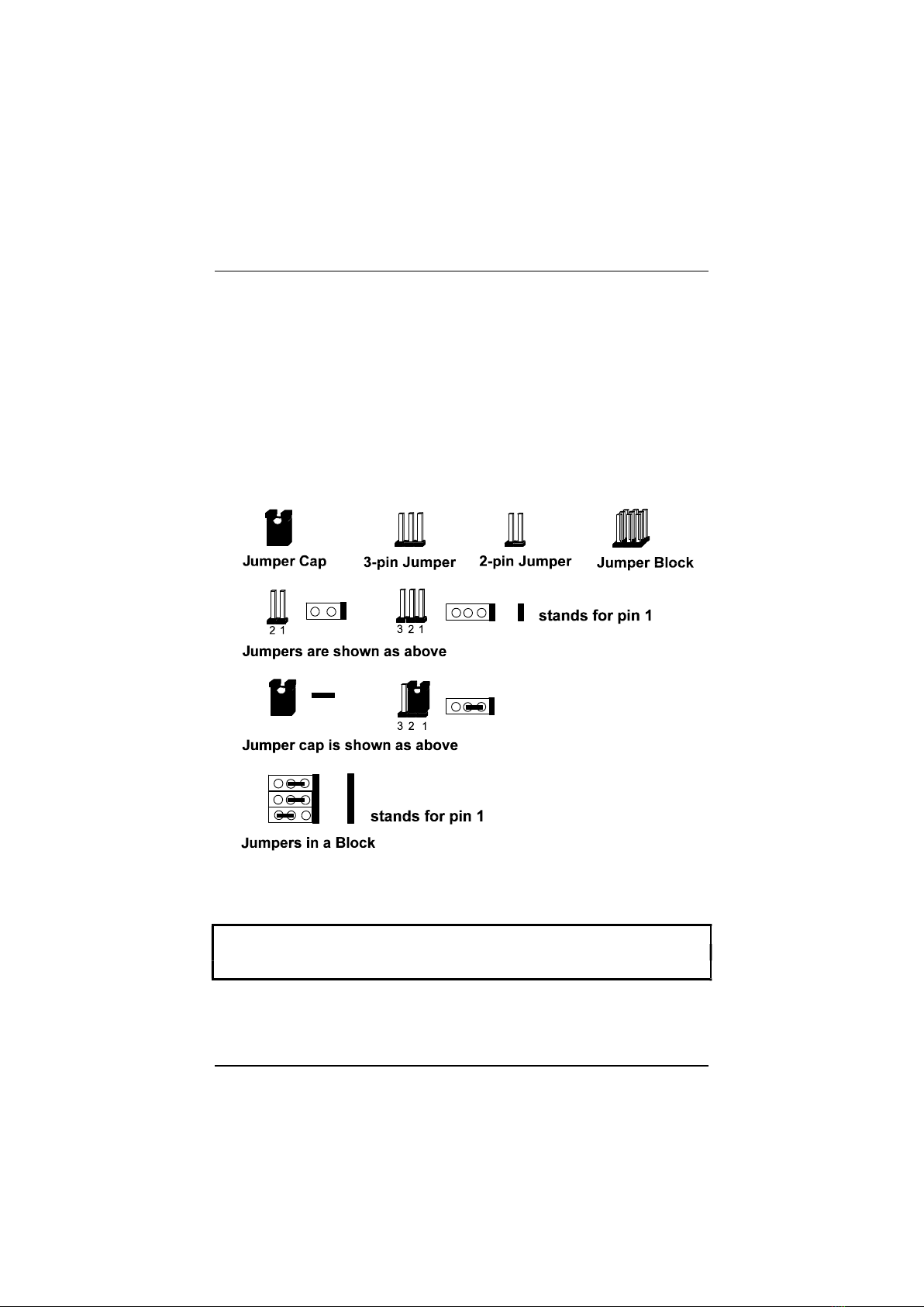
Jumpers are used to select the operation modes for your system. Some
jumpers on the board have three metal pins with each pin representing a
different function. To set a jumper, a black cap containing metal contacts is
placed over the jumper pin/s according to the required configuration. A
jumper is said to be shorted when the black cap has been placed on one or
two of its pins. The types of jumpers used in this manual are shown below:
NOTE : Users are not encouraged to change the jumper settings not listed in
this manual. Changing the jumper settings improperly may adversely affect
system performance.

VT-502 Mainboard Manual
12
Clear Password: CPW
This jumper allows you to set the password configuration to Enabled or
Disabled. You may need to enable this jumper if you forget your password.
Flash EPROM Type Selection: EP1, EP2
These two jumpers allow you to configure the Flash EPROM chip
Installation Procedures
13
2). Install System RAM Modules
DRAM and SDRAM
The working space of the computer is the Random Access Memory (RAM).
The system cannot act upon data unless it is loaded into RAM. When more
memory is added, the working memory of the computer is larger, thereby
increasing total performance.
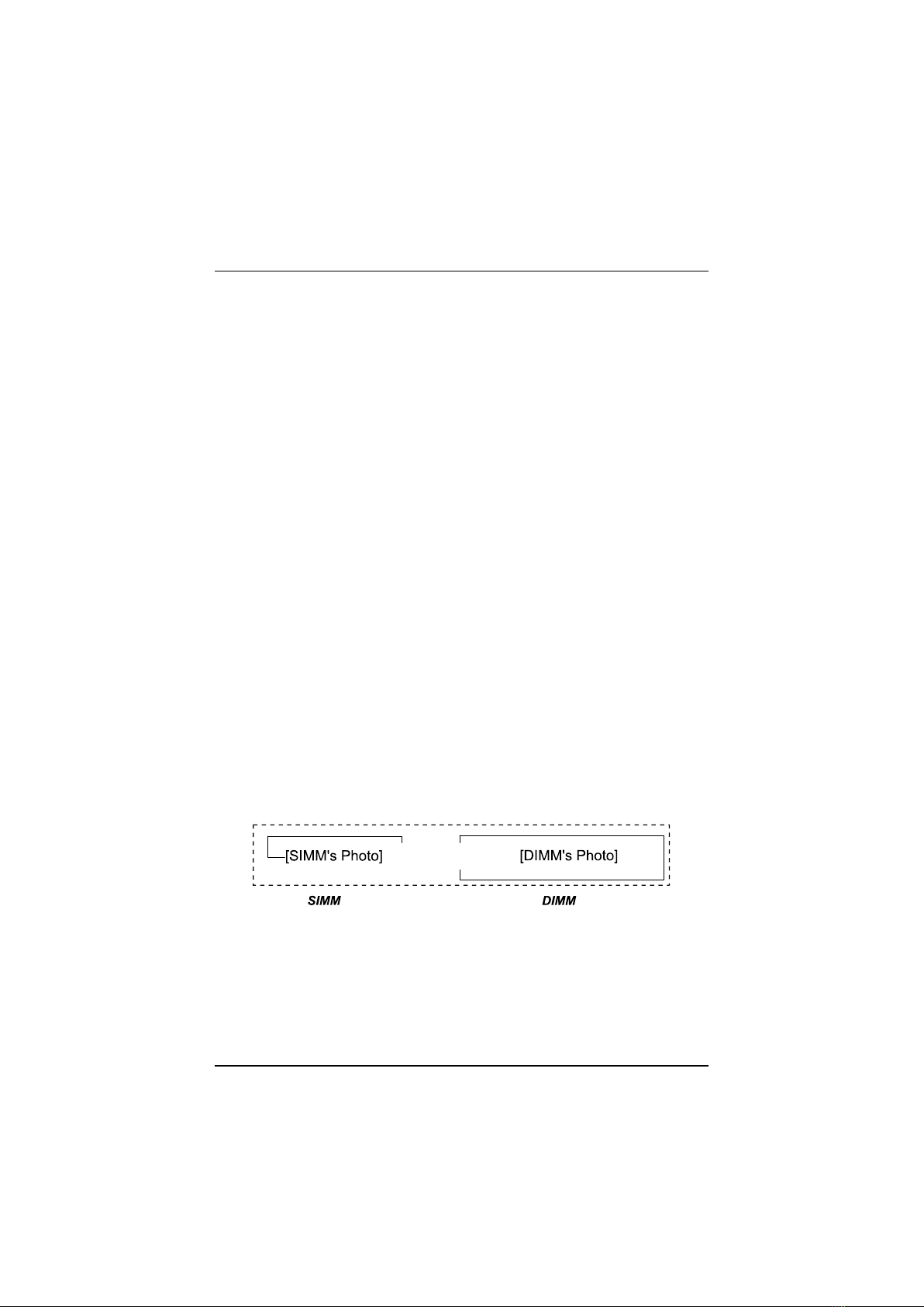
The VT-502’s RAM is comprised of four industry standard 72-pin Single
In-line Memory Modules (SIMMs) and two 168-pin Dual In-line Memory
Modules (DIMMs). Each SIMM socket supports from 4 to 128MB FPM (Fast
Page Mode) and high-speed EDO (Extended Data Out) DRAM. Each DIMM
socket is able to support up to 64MB EDO DRAM and lightning-fast SDRAM
(Synchronous DRAM).
SDRAM is an advanced new memory technology that boosts overall system
performance with its ability to synchronize all operations with the
processor clock signal. This makes the implementation of control interfaces
easier, and speeds up column access time. SDRAM features an on-chip burst
counter that can be utilized to increment column addresses for very fast
burst access, which means that SDRAM allows new memory access to be
initiated before the preceding access has been finished.
Before making DRAM upgrades you should verify the type and speed of the
RAM currently installed from your dealer. Installing mixtures of RAM types
other than those described in this manual, will have unpredictable results.
VT-502 Mainboard Manual
14
RAM Module Configuration
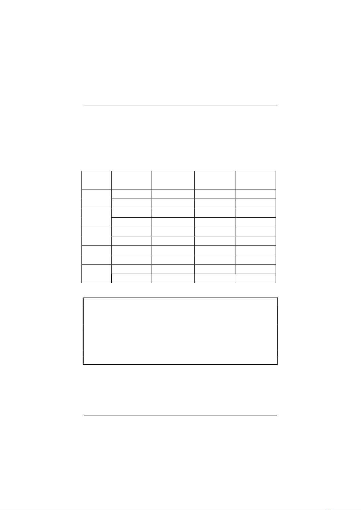
SIMMs and DIMMs in Bank 0 and Bank 1 can be installed in many
combinations. Some of them are listed in the following table. Please note
that SIMMs and DIMMs should not be installed at the same time.
(Unit : MB)
TOTAL
MEMORY
SIMM 1 & 2
(Bank 0)
SIMM 3 & 4
(Bank 1)
DIM1
(Bank 0)
DIM2
(Bank 1)
8 4 & 4
8
16 8 & 8
16
32 16 & 16
32
64 32 & 32
64*
128 64 & 64
64* 64*
NOTE :
1. * A RAM module of this size was not available for testing at press time.
2. DIM1 and DIM2 only support 3.3V (unbuffered) EDO and SDRAM |||||
modules.
3. DIM1 and SIMM1 are shared, so are DIM2 and SIMM2. That is, it is not
allowed to install RAM modules on DIM1 and SIMM1 at the same time,
or on DIM2 and SIMM2 at the same time.
4. This mainboard supports the SIMMs (without ECC support or parity
check) with latency time are 70ns, 60ns; and DIMMs with latency times
of 10ns, 12ns.
Installation Procedures
15
Install SIMMs
Complete the following procedures to install SIMMs:
CAUTION : Always turn the system power off before installing or removing
any device; and see “Handling Precautions” at the start of this manual.
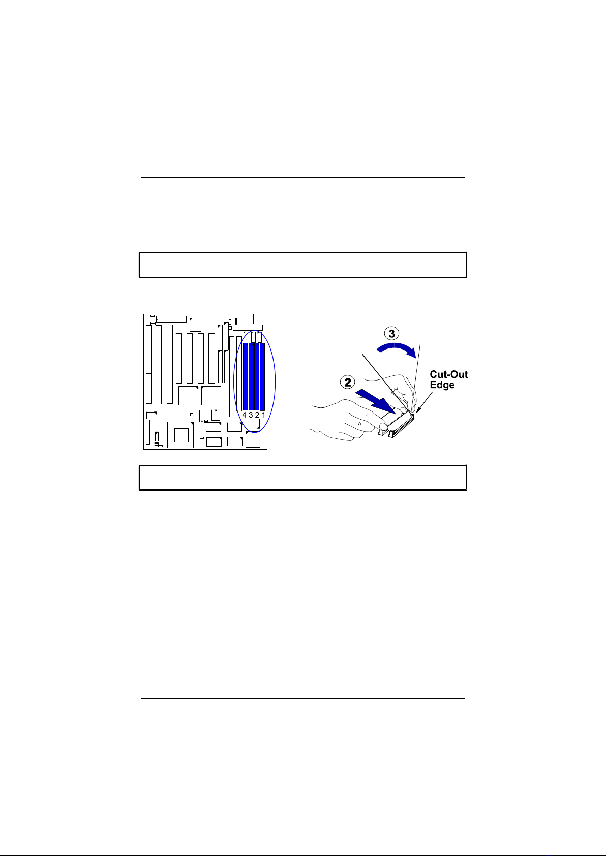
1. Locate the SIMM slots on the mainboard. (See figure below.)
NOTE : SIMMs in each bank must be of the same type; and the BIOS
automatically configures the memory size.
2. Carefully fit a SIMM at a 45 degree angle into each empty socket to be
populated. All the SIMMs must face the same direction.
3. Swing each SIMM into its upright, locked position.
When locking a SIMM in place, push on each end of the SIMM - do not
push in the middle, as shown above.
Remove SIMMs
To remove the SIMMs, pull the retaining latch on both ends of the socket
and reverse the procedure above.
VT-502 Mainboard Manual
16
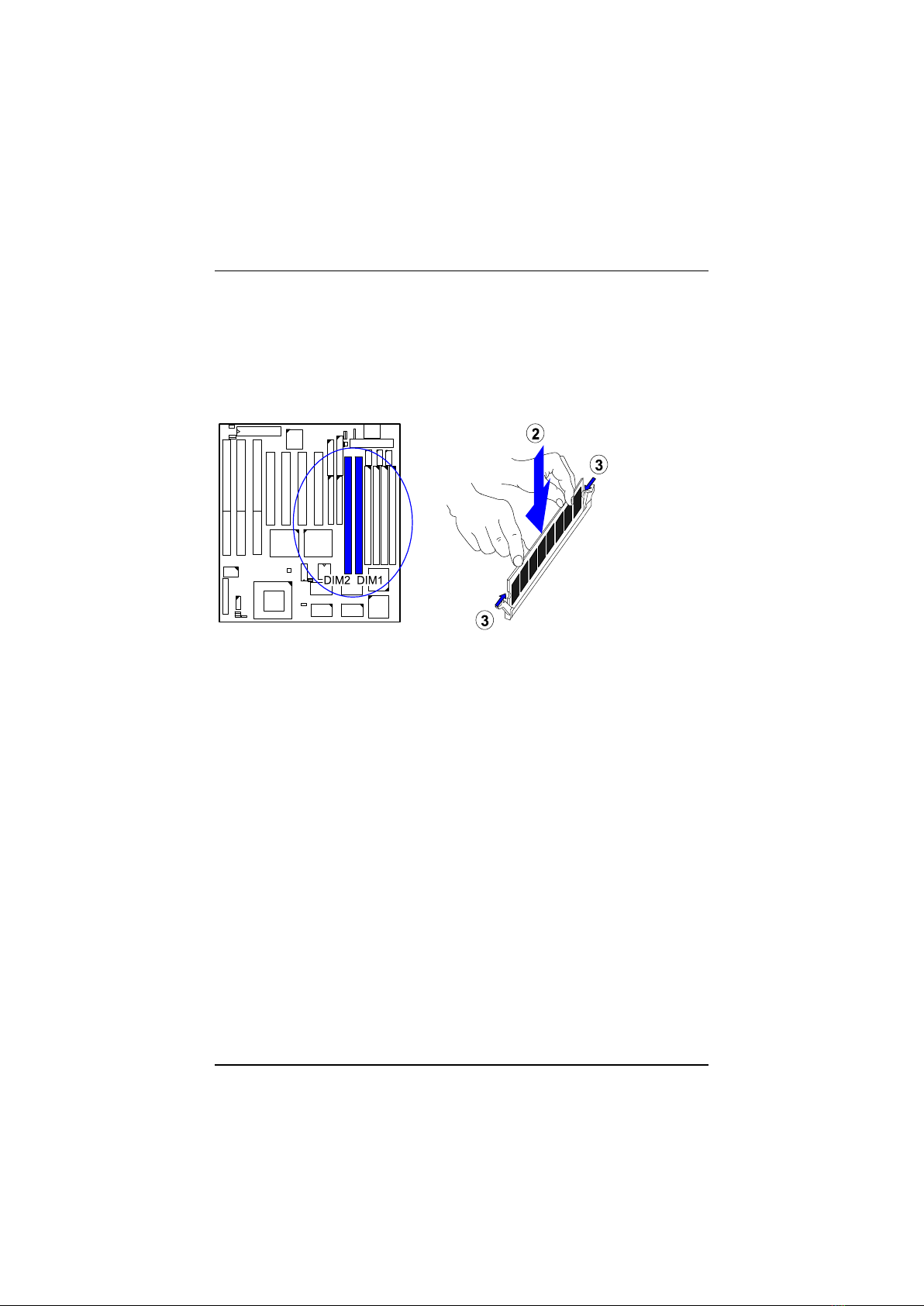
Install DIMMs
Complete the following procedures to install DIMMs:
1. Locate the DIMM slots on the mainboard.
2. Install the DIMM straight down into the DIMM slot with both hands.
3. The clips of the slot will close up to hold the DIMM in place when the
DIMM touches the slot’s bottom.
Remove DIMMs
Press the clips with both hands to remove the DIMM.
Table of contents
Other FIC Motherboard manuals


