FIC P4-875P MAX User manual

875 Dynasty
MAINBOARD
MANUAL
DOC No.: M03207
Rev. :A2
Date : 6, 2003
Part No. : 25-11242-02
P4-875P MAX

Handling Precautions
Warning:
1. Static electricity may cause damage to the integrated circuits on
the motherboard. Before handling any motherboard outside of its
protective packaging, ensure that there is no static electric charge
in your body.
2. There is a danger of explosion if the battery is incorrectly
replaced. Replace only with the same or an equivalent type
recommended by the manufacturer.
3. Discard used batteries according to the manufacturer’s
instructions.
4. Never run the processor without the heatsink properly and firmly
attached. PERMANENT DAMAGE WILL RESULT!
Observe the following basic precautions when handling the motherboard
or other computer components:
Wear a static wrist strap which fits around your wrist and is
connected to a natural earth ground.
Touch a grounded or anti-static surface or a metal fixture such as a
water pipe.
Avoid contacting the components on add-on cards, motherboards,
and modules with the golden fingers connectors plugged into the
expansion slot. It is best to handle system components by their
mounting brackets.
The above methods prevent static build-up and cause it to be discharged
properly.
Trademark
All trademarks mentioned in this manual are registered properly of
the respective owners.
Handling Precautions
This manual may not, in whole or in part, be photocopied, reproduced,
transcribed, translated, or transmitted in whatever form without the
written consent of the manufacturer, except for copies retained by the
purchaser for personal archival purposes.
Notice

i
Table of Contents
Table of Contents
Chapter 1 Overview
Package Checklist .......................................................................... 1-2
P4-875P MAX ............................................................................ 1-3
Main Features ................................................................................ 1-4
FIC Unique Innovation for Users (NOVUS) -
Enhanced Mainboard Features and System Support .................... 1-6
Chapter 2 Installation Procedures
1). Set System Jumpers .................................................................. 2-2
Clear CMOS ...................................................................... 2-2
BIOS Protect ...................................................................... 2-3
2). Install Memory Modules .......................................................... 2-4
3). Install the CPU .......................................................................... 2-5
Connect ATX Power .......................................................... 2-6
4). Install Expansion Cards ............................................................. 2-7
5). Connect Devices ....................................................................... 2-9
Floppy Diskette Drive Connector ...................................... 2-9
IDE Device Connectors ..................................................... 2-9
Fan Connectors ................................................................. 2-10
Power Connectors ............................................................. 2-11
System Chassis Open Alarm Connector ............................ 2-11
SPDIF Out Connector ....................................................... 2-12
Debug LEDDisplay Connector ......................................... 2-12
Front Panel Block, Power LED, IR, and Speaker Connector 2-13
Serial ATA Connectors ...................................................... 2-14
CDAudio-In Connector .................................................... 2-15
1394 Connectors ................................................................ 2-15
PS/2 Keyboard and Mouse Connector .............................. 2-16
RJ45 LAN Connector ........................................................ 2-16
Serial Port Connectors ....................................................... 2-17
Printer Connector .............................................................. 2-17

ii
875 Dynasty Mainboard Manual
Chapter 3 BIOS Setup
CMOS Setup Utility ....................................................................... 3-1
Standard CMOS Setup ................................................................... 3-2
Advanced BIOS Features .............................................................. 3-4
Advanced Chipset Features .......................................................... 3-8
Integrated Peripherals .................................................................... 3-10
Power Management Setup ............................................................. 3-14
PnP/PCI Configurations ................................................................. 3-18
PC Health Status ............................................................................ 3-19
Frequency/Voltage Control ............................................................ 3-20
Load Fail-Safe Defaults .................................................................. 3-21
Load Optimized Defaults ................................................................ 3-21
Supervisor/User Password ............................................................ 3-21
Save and Exit Setup ........................................................................ 3-22
Exit without Saving ........................................................................ 3-22
Audio I/O Jacks ................................................................ 2-18
Front Audio Connector ..................................................... 2-18
5.1 Audio Channel Feature ................................................ 2-19
Universal Serial Bus Connectors ....................................... 2-20

1 - 1
Overview
Overview
Chapter 1
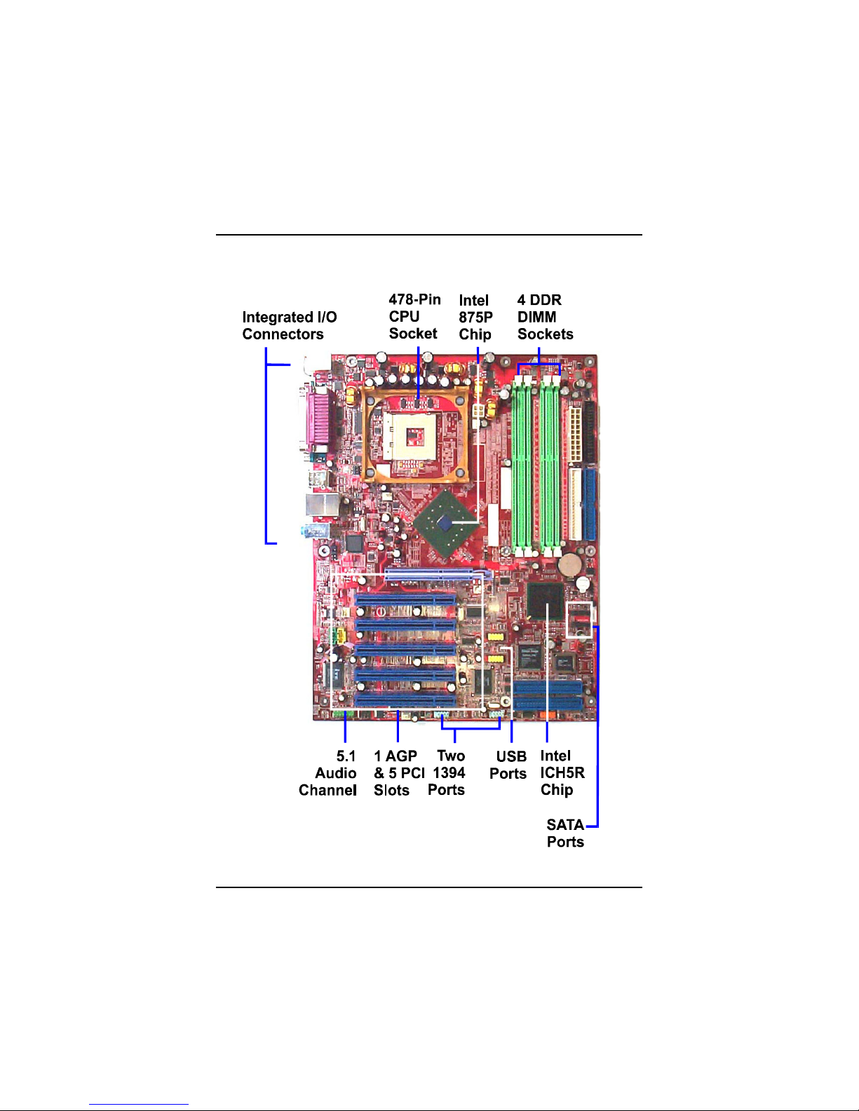
The new ATX, 478-pin 1stMainboard®supports a full range of the latest
generation Intel®Pentium®4 processors. The leading edge Intel®chipset
was designed for coworking with Pentium®4 (up to 3.0 GHz) in the 478-pin
package based on the VRM 10.0 spec and 533/ 800 MHz.Built using the leading
edge technology the Intel Pentium®4 processors provide a significant perfor-
mance over previous Pentium®III processors. Four DDR 333/400 SDRAM
sockets allow for up to 4 GB memory capacity. Support for the Ultra DMA/100
protocol and its high-speed interface further ensures that data transfer speeds
are improved, especially for long sequential transfers required by audio/visual
applications.
The board features onboard audio and LAN function; also, the serial ATA
feature replaces the standard parallel ATA physical storage interface and al-
lows future enhancements to the computing platform. It completely software
compatible with parallel ATA, requiring no mofication to your operating sys-
tem. Two types of RAID connections are provided: IDE (HPT 372) and SATA
(Intel ICH5R). The onboard serial ATA feature includes RAID function to
provide you with a more efficient storage backup. For more detail, please read
the help file in the lst Utilities CD.
The 1stMainboard comes with a versatile range of I/O features such as 2 serial
ports, 2 IDE RAID, 2 serialATA ports, 1 parallel port, 1 LAN, 2 IEEE 1394, 1 PS/
2 mouse and keyboard connector, 8 USB ports, 5.1 audio channel, 1 media
connector (front audio, Line-in, Line-out and Mic-in). In addition, the board is
equipped with 2 dual channel enhanced PCI bus master IDE connectors. Ample
expansion is available through 5 PCI and 1AGP to meet the requirement for
enjoying the P4 CPU benefits in internet applicatons, video/3D graphics per-
formance, and so forth.
Other key features are Remote On/Off, Auto Power Failure Recovery, inte-
grated temperature monitoring and system fan control. Included also is lst
Utilities CD with enhanced drivers and a few bundled soft-ware solutions.

1 - 2
875 Dynasty Mainboard Manual
NOTE: lst Utilities CD that contains patch files, onboard video/au-
dio chip drivers, related online help and other useful information
can be found in your mainboard package.
Please install it right after your Windows operating system installa-
tion is done.Place your lst Utility in the drive, an operating menu will
appears in your monitor. Please select Auto Installation. It will auto-
matically detect which software tools (patch files, drivers) that the
mainboard needs. Press OK button to go through the whole instal-
lation procedure in a very straight forward and easy way. It also
provides you with a custom way to select wanted patch files and
software drivers that for onboard chips use. The top menu of lst
Utilities lists all the functions that allowed by this board.
Package Checklist
If you discover any item below was damaged or lost, please contact your
vendor.
1 - 3
Overview
P4-875P MAX

1 - 4
875 Dynasty Mainboard Manual
Main Features
CPU
Pentium®4:
2.26 to 2.8 GHz (FSB 533) and up*
2.4 to 3.0 GHz (FSB 800) and up*
(*: not tested yet)
Chipset
North Bridge: Intel®875P
South Bridge: Intel®ICH5R
Memory
4 memory sockets :
support 184-pin DDR 333/ 400
memory size totally upto 4 GBz
The combinations of FSB/DDR: (must followed)
FSB DDR
800 400
800 333
533 333
Expansion Slots
1 AGP Slot : support 3.0 4X/8X (0.8V/1.5V);
5 PCI Slots
IDE Connections
2 IDE connectors - PIO mode, Ultra DMA 66/100
up to 4 devices
SATA Connections
2 ports controlled by embeded ICH5R®SATA function
level 0/1* RAID functions (*: not tested yet)

1 - 5
Overview
I/O Ports
2 IDE connectors -
PIO, Bus Master, Ultra DMA 66/100
up to 4 devices
2 serial ports COM1 and COM2
1 parallel port
PS/2 mouse and PS/2 keyboard
8 USB 2.0 ports
LAN
Two options: Intel Kenai 10/100 Ethernet or Giga-LAN
IEEE 1394 Ports
Agere FW323
2 ports
1 bracket with cable
Mounting Holes
9 holes
Mainboard Size
12 x 9.6 (unit: inch)
Audio Features
Realtek ALC650 controller
AC97 2.2 compliant
LINE_IN, LINE_OUT, MICROPHONE_IN Jack
5.1 audio channel
A73 audio bracket with cable (optional)
front audio pinheaders
RAID (IDE) Connections
2 ports controlled by HighPoint 372®RAID function
Level 0, 1, 0+1
up to 4 devices

1 - 6
875 Dynasty Mainboard Manual
BIOS Guardian
BIOS Guardian effectively acts as a fire-wall against viruses that can at-
tack the BIOS while the system is running and by default is enabled.
WARNING:
BIOS Guardi an must be disa bled bef ore refla s h BIOS.
NOTE:
Please read Page 3-7 for detail information.
FIC Unique Innovation for Users (NOVUS) -
Enhanced Mainboard Features and System Support
LogoGenie
A user friendly GUI supporting Windows 95/98SE (not Windows 2000/
NT/ME/XP), LogoGenie allows you to customize, create or select a Logo
which will be displayed when the system is booting.
NOTE:
Please read Page 3-7 for detail information.
Easy Key
Instead of completing the multi-layered BIOS setup process these 3 Easy
Key functions provide direct access to Sub-Menu when completing BIOS
settings adjustments.
Easy-Keys are as follows:
Ctrl + c: To enter clock settings menu.
Ctrl + p: To load Performance Default settings and restart.
Ctrl + f: To load Fail-Safe Default settings and restart.

2-1
Installation Procedures
Chapter2
Installation Procedures
Themainboardhasseveraluser-adjustablejumperson theboardthatallowyou to
configureyoursystemtosuit yourrequirements.Thischaptercontainsinformation
on thevariousjumpersettingson yourmainboard.
Tosetup yourcomputer,you mustcompletethefollowing steps:
Step1-Setsystemjumpers
Step2-Install memorymodules
Step3-Install theCentralProcessingUnit(CPU)
Step4-Install expansioncards
Step5-Connectribboncables,cabinetwires,and power supply
Step6-Setup BIOSsoftware
Step7-Install supportingsoftware tools
WARNING:Excessivetorque maydamage the mainboard.When
using an electricscrewdriveron the mainboard,makesurethat
the torque issettothe allowablerange of5.0~8.0kg/cm.
MainboardcomponentscontainverydelicateIntegrated Circuit
(IC)chips.Topreventstaticelectricityfromharming anyofthe
sensitivecomponents,you shouldfollowthe following precau-
tionswheneverworking on the computer:
1.Unplug the computerwhen working on the inside.
2.Holdcomponentsbythe edgesand trynottotouchthe IC
||||chips,leads,orcircuitry.
3.Wearan anti-staticwriststrap whichfitsaround the wrist.
4.Placecomponentson agrounded anti-staticpad oron the bag
thatcamewiththe componentwheneverthe componentsare
separated fromthe system.

2-2
875 DynastyMainboardManual
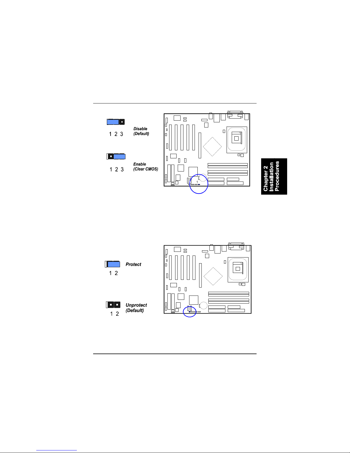
ClearCMOS
TheCMOSRAMispoweredby theonboardbutton cell battery.To
cleartheRTCdata:
(1)Turnoff yourcomputer;
(2)openthesystemcase,disconnecttheATXpowercable;
(3)place thejumpercapontothepinpair2-3atleast6secondstoenable
CMOSclearance;
NOTE:Usersarenotencouraged tochange the jumpersettings
notlisted inthismanual.Changing the jumpersettingsimproperly
mayadverselyaffectsystemperformance.
(4)place thejumpercapontothepinpair1-2todisabletheeffectofCMOS
clearance;
(5)connecttheATXpowercable;closethesystemcase;
(6)turnon yourcomputeruntil CMOSchecksumerrorappears;
(7)holddowntheDeletekeywhenboots;
(8)entertheBIOSSetup tore-enteruserpreferences.
1).SetSystemJumpers
Jumpersareusedtoselecttheoperation modesforyoursystem.Somejump-
erson theboardhavethree metalpinswitheachpinrepresenting adifferent
function.A1iswrittenbesidespin1on jumperswiththree pins.Toseta
jumper,ablackcapcontaining metalcontactsisplacedoverthejumperpin/s
according totherequiredconfiguration.Ajumperissaidtobeshortedwhen
theblackcaphasbeenplacedon oneortwoofitspins.
2-3
Installation Procedures
BIOSProtect
Thejumperhelpsuserstopreventthe64Kbootblocktablearea inthe
BIOSROMfrombeing overwrittenby mistake.
2-4
875 DynastyMainboardManual
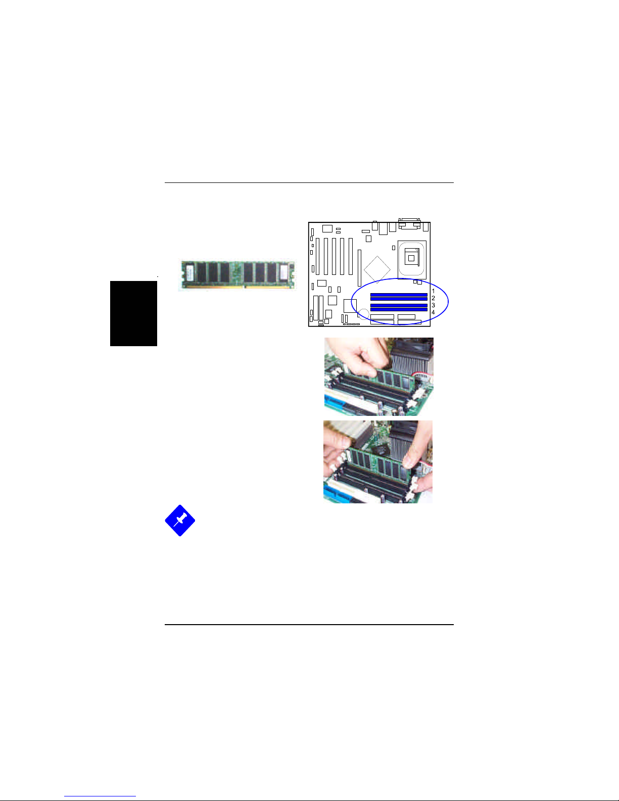
Press theclipswithbothhandstoremovetheDIMM.
2).Install MemoryModules
1.LocateDDRDIMM sockets
on themainboard.
2.InstallDDRDIMM straightdown
intothesocket1using bothhands,
thensocket2,and soforth.
3.Theclipon bothendsofthe
socketwill closeup toholdthe
DDRDIMM inplace whentheDDR
DIMM reachesthesocketbottom.
NOTE:
1.Toenabledualchannel,itmustbe-
samedensity(128/256MB,etc.);sametechnology(128/256Mb,etc.);
samebuswidth(x8,x16);bothsingle-(ordual-) sided;installed on
symmeticalmemoryslots.
2.If yoursystemusesan 800MHzCPUwithDDR333 memory,the
memoryinterfaceofthe chipsetwill run at320MHzonly.(Please
read Page 1-4,Memoryfordetails.)

2-5
Installation Procedures
3).Install theCPU
1.Swing theleverupwordto90 degree.
2.Install theCPUand makesurethethepin1
orientation by aligning thesocketcornermarking
withthesocketcornerclosesttothelevertip.
DonotinserttheCPUby force.Makesurethe
processorisfullyinsertedintothesocketon all
sides.
Applysomethermalmaterials,suchaspasteor
tape,on theCPUtop;and install afanwith
heatsink thatapprovedby CPUmanufacturer
toavoidCPUdamage.Fordetail information,
pleaserefertotheCPUmanufacturerwebsite.
Themainboardhasbuilt-inSwitching VoltageRegulatortosupportCPUVcore
autodetection.Thatis,Ithastheabilitytodetectand recognize theCPUvolt-
age,clock,ratioand enablesuserstosetup theCPUfrequencyfromtheBIOS
Setup Screen.Userscanadjustthefrequencythrough Frequency /Voltage
ControloftheBIOSSetup Screen.
Theproceduresbelowshowsyou howtoinstall yourCPUand itsfan
and heatsink.Firstofall,locatetheCPUsocketon thismainboard.
2-6
875 DynastyMainboardManual
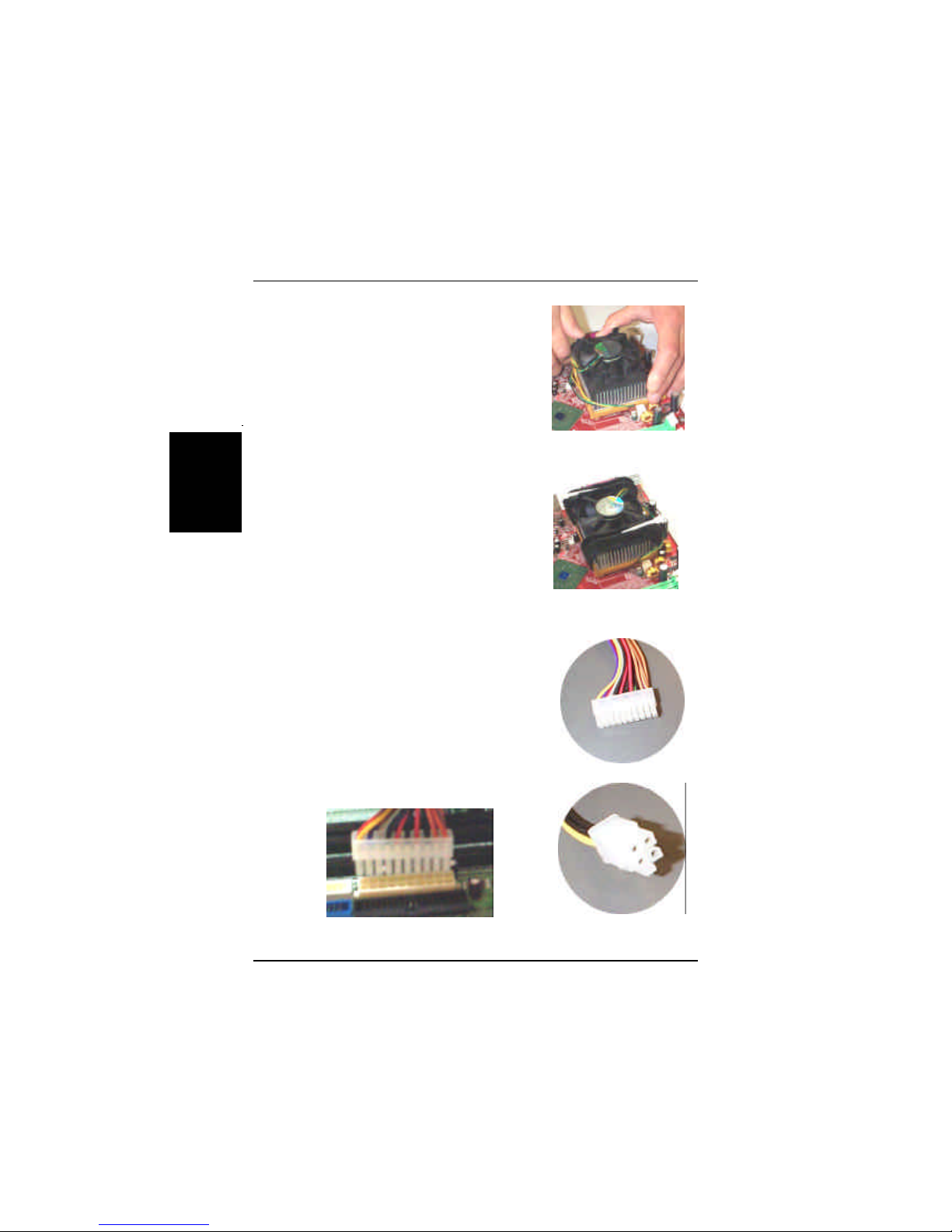
3.Place thefanwithheatsink on theCPUtop
and press downtwoplasticclipstohook up
withtheholeson theretention moduleon two
sides.
4.Press downthewhitebaron eachclipto
fastenthefanseton theretention module.
AffixtheCPUby pressing theleverdownward
and locking it besidethesocket.
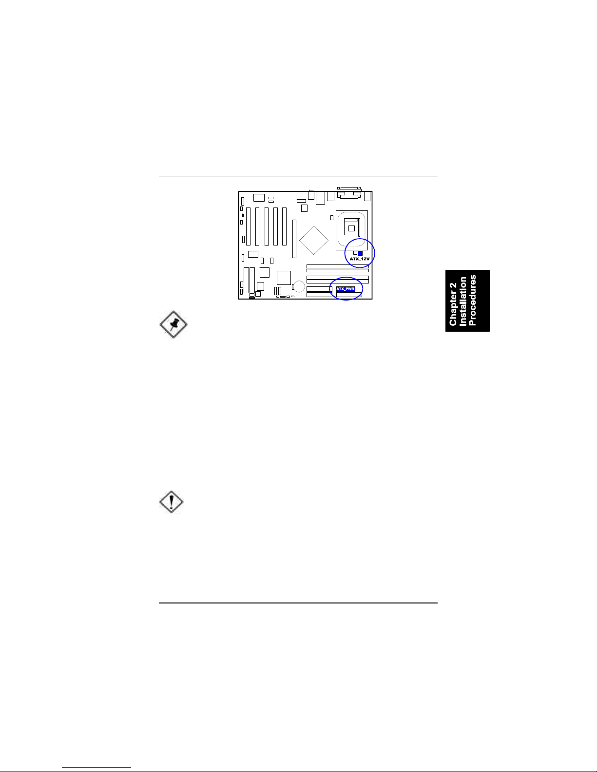
ConnectATXPower
The20-holepowerplug (top right)isconnected
totheATXpower20-pinpinheaders.The4-hole
12Vpowerplug (bottomright)isinsertedinthe
ATX_12Vpowerconnector.
Theplug fromthepowersupplywill onlyinsert
inoneorientation becauseofthedifferenthole
sizes.Find theproperorientation and pushdown
firmlymaking surethatthepinsarealigned.
2-7
Installation Procedures
CAUTION:
1.Makesuretounplug the powersupplywhen adding orremoving
expansion cardsorothersystemcomponents.Failuretodo so
maycauseseveredamage toboththe mainboardand expansion
cards.
2.Always observestaticelectricityprecautions.
3.Pleaseread Handling Precautionsatthe startofthismanual.
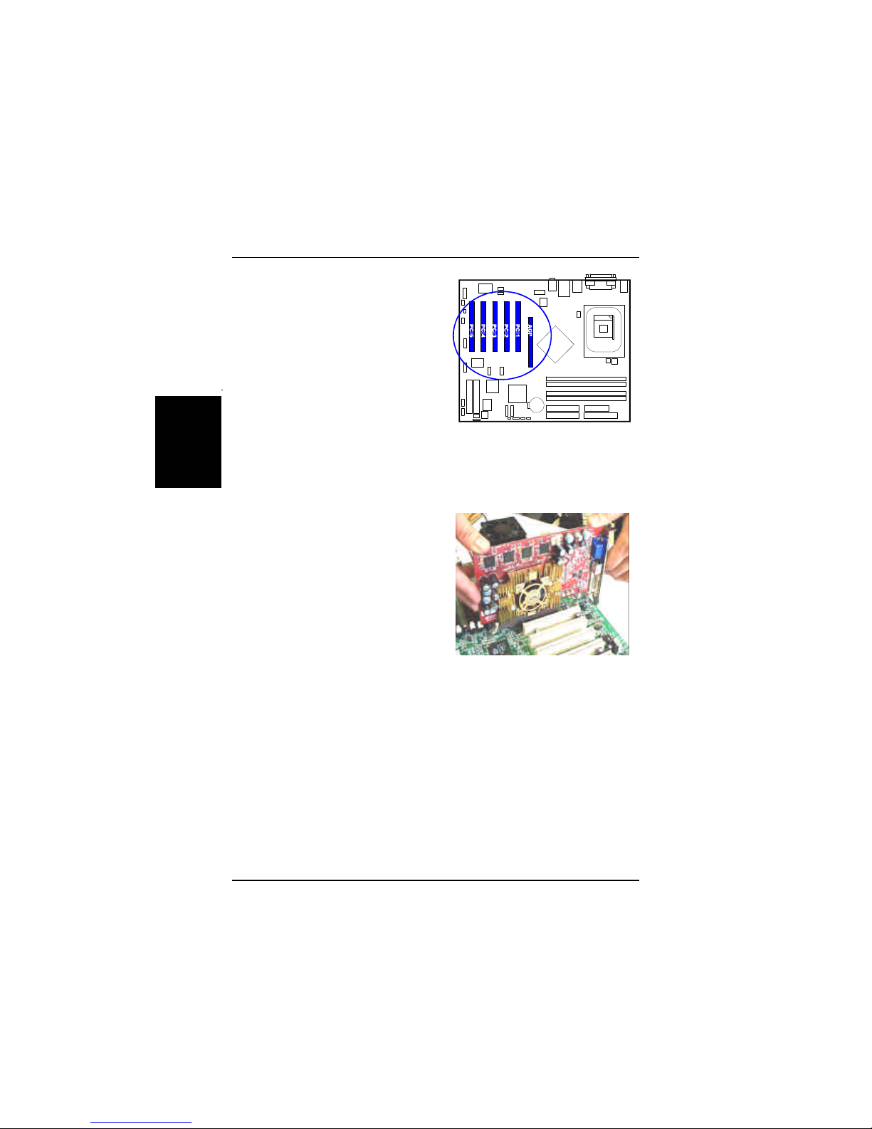
4).Install Expansion Cards
Thissection describeshowtoconnectanexpansion cardtooneofyour
systemexpansion slots.
Expansion cardsareprintedcircuit boardsthat,whenconnectedtothe
mainboard,increasethecapabilitiesofyoursystem.
Forexample,expansion cardscanprovidevideoand sound capabilities.The
mainboardfeaturesoneAGPand three PCIbusexpansion slots.
NOTE:UsersThe CPUinstalling proceduresshouldbe:
1.Insertthe CPU(withitsfansinkand retention module)on the
socket.
2.Connectthe 4-pinplug ofthe powersupply
3.Connectthe 20-pinplug ofthe powersupply.
Toremovethe processor,pleasedo itinreverseorder.
2-8
875 DynastyMainboardManual
1.Selectanavailableexpansion slot.
2.Removethecorresponding slotcoverfromthecomputerchassis.Un-
screwthemounting screwthatsecurestheslotcoverand pull theslotcover
outfromthecomputerchassis.Keeptheslotcovermounting screwnearby.
3.Pushthecardfirmlyintotheslot.
Pushdownon oneend oftheexpan-
sioncard,thentheother.Usethisrock-
ing motion until themcardisfirmly
seatedinsidetheexpansion slot.Se-
curethecardwiththescrewremoved
inStep2.
2-9
Installation Procedures
5).ConnectDevices
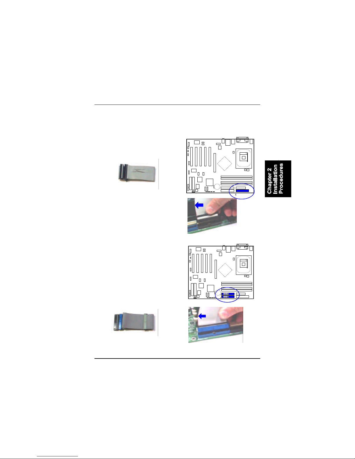
FloppyDisketteDrive Connector
Thisconnectorprovidestheconnection withyourfloppy diskdrive.
Insertthefloppy ribbon cable(below)
ontothefloppy connector.
Thecoloredstripe(indicatedby the
arrowhead,right)oftheribbon cable
mustbethesamesidewiththePin1.
Insertthefloppy ribbon cable(below)
ontothefloppy connector.
Thecoloredstripe(indicatedby the
arrowhead,right)oftheribbon cable
mustbethesamesidewiththePin1.
IDEDevice Connectors
Thetwoconnectors,PRIMARYandSEC-
ONDARY,areusedforyourIDEharddisk
drives,CDdrives,LS-120|drives,orIDE
ZIPdrives.Theredstripeoftheribbon
cablemustbethesamesidewiththePin
1.Thetwoconnectors,IDE3and IDE4,
areoptional.Theyarelinkedwithyour
RAIDdevices(level0,1,0+1).IDE3and
IDE4supportstorageharddisksonly.
2-10
875 DynastyMainboardManual
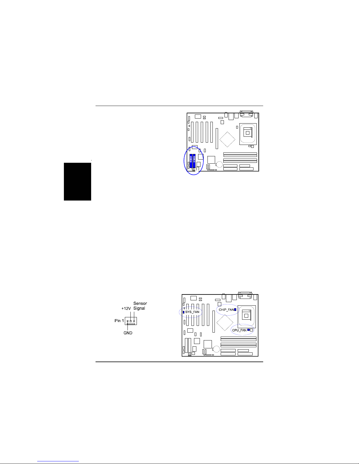
FanConnectors
Thetwoconnectors,CPU_FAN,SYS_FANarelinkedtotheCPUfan,casefan,
respectively.CHIP_FAN canbeusedwithNorthBridgechipfan.
Assumethatuserswanttoinstall their
operating systemsinabrand newhard
drivethatconnectedtoIDE3connec-
toroftheboard.Press thekeyCtrland
Hduring booting toentertheBIOS
utilityand seteachharddrivelevel.
Saveand exit.Rebootthesystem.Be-
gintoinstall theoperating systemand
drives.
If install Windows2000/NT/XPon aharddiskthatconnecttoIDE3orIDE4
connector:
1.Copy all filesinthesubdirectory\RAID\HighPointtofloppy diskon
anothercomputer.
[Forexample]
If driverCDisDdriveand thefloppy driveisA.
ExecuteWindowsExplorer\SelectAll\ Send toA:
orgo toDOSprompt,
D:\RAID\HighPoint>xcopy /s*.*A:tocopy all RAIDdrivers.
2.Asinstallation begins,press F6key,thenSkeytocopy filesfromA:.
3.Afterall filescopied,press Entertoinstall it.
4.Completetherestinstallation procedures.
Table of contents
Other FIC Motherboard manuals


 user manual")


