FIC 1stMainboard VC15 User manual

VC15
MAINBOARD
MANUAL
DOC No.: M01807
Rev. :A0
Date : 10, 2001
Part No. : 25-11632-00

Handling Precautions
Warning:
1. Static electricity may cause damage to the integrated circuits on
the motherboard. Before handling any motherboard outside of its
protective packaging, ensure that there is no static electric charge
in your body.
2. There is a danger of explosion if the battery is incorrectly
replaced. Replace only with the same or an equivalent type
recommended by the manufacturer.
3. Discard used batteries according to the manufacturer’s
instructions.
4. Never run the processor without the heatsink properly and firmly
attached. PERMANENT DAMAGE WILL RESULT!
Observe the following basic precautions when handling the motherboard
or other computer components:
nWear a static wrist strap which fits around your wrist and is
connected to a natural earth ground.
nTouch a grounded or anti-static surface or a metal fixture such as a
water pipe.
nAvoid contacting the components on add-on cards, motherboards,
and modules with the golden fingers connectors plugged into the
expansion slot. It is best to handle system components by their
monting brackets.
The above methods prevent static build-up and cause it to be discharged
properly.
Trademark
All trademarks mentioned in this manual are registered properly of
the respective owners.
Handling Precautions
This manual may not, in whole or in part, be photocopied, reproduced,
transcribed, translated, or transmitted in whatever form without the
written consent of the manufacturer, except for copies retained by the
purchaser for personal archival purposes.
Notice

i
Tableof Contents
Table of Contents
Chapter 1 Overview
Package Checklist .......................................................................... 1-1
The VC15 Mainboard ................................................................ 1-2
Main Features ................................................................................ 1-3
FIC Unique Innovation for Users (NOVUS) -
Enhanced Mainboard Features and System Support ..................... 1-5
Chapter 2 Installation Procedures
Quick Reference (from Page 2-2 to 2-4) .......................................... 2-2
Mainboard Layout .................................................................... 2-2
1). FSB Speed Select, Clear CMOS, Clear Password, ......... 2-3
2). Front Panel Block Cable Connection ............................ 2-3
3). CPU Fan Installation ..................................................... 2-4
1). Set System Switches ................................................................. 2-4
FSB Speed Select: FS1 ....................................................... 2-4
Clear CMOS: JP1 ............................................................... 2-5
Clear Password: JP1 .......................................................... 2-5
2). Install Memory Modules .......................................................... 2-6
3). Install the CPU .......................................................................... 2-6
4). Install Expansion Cards ............................................................. 2-7
5). Connect Devices ....................................................................... 2-9
Floppy Diskette Drive Connector ..................................... 2-9
IDE Device Connectors ..................................................... 2-10
Power Connectors ............................................................. 2-10
Fan Connectors ................................................................. 2-11
Wake-On-LAN Connector ................................................. 2-11
CD Audio-In Connector .................................................... 2-12
Quick Reference (German) G-1
Quick Reference (French) F-1
Quick Reference (Spanish) S-1
Quick Reference (Japanese) J-1
Quick Reference (Chinese) C-1
Quick Reference (Simplified Chinese) |||||||||||||SC-1

ii
VC15MainboardManual
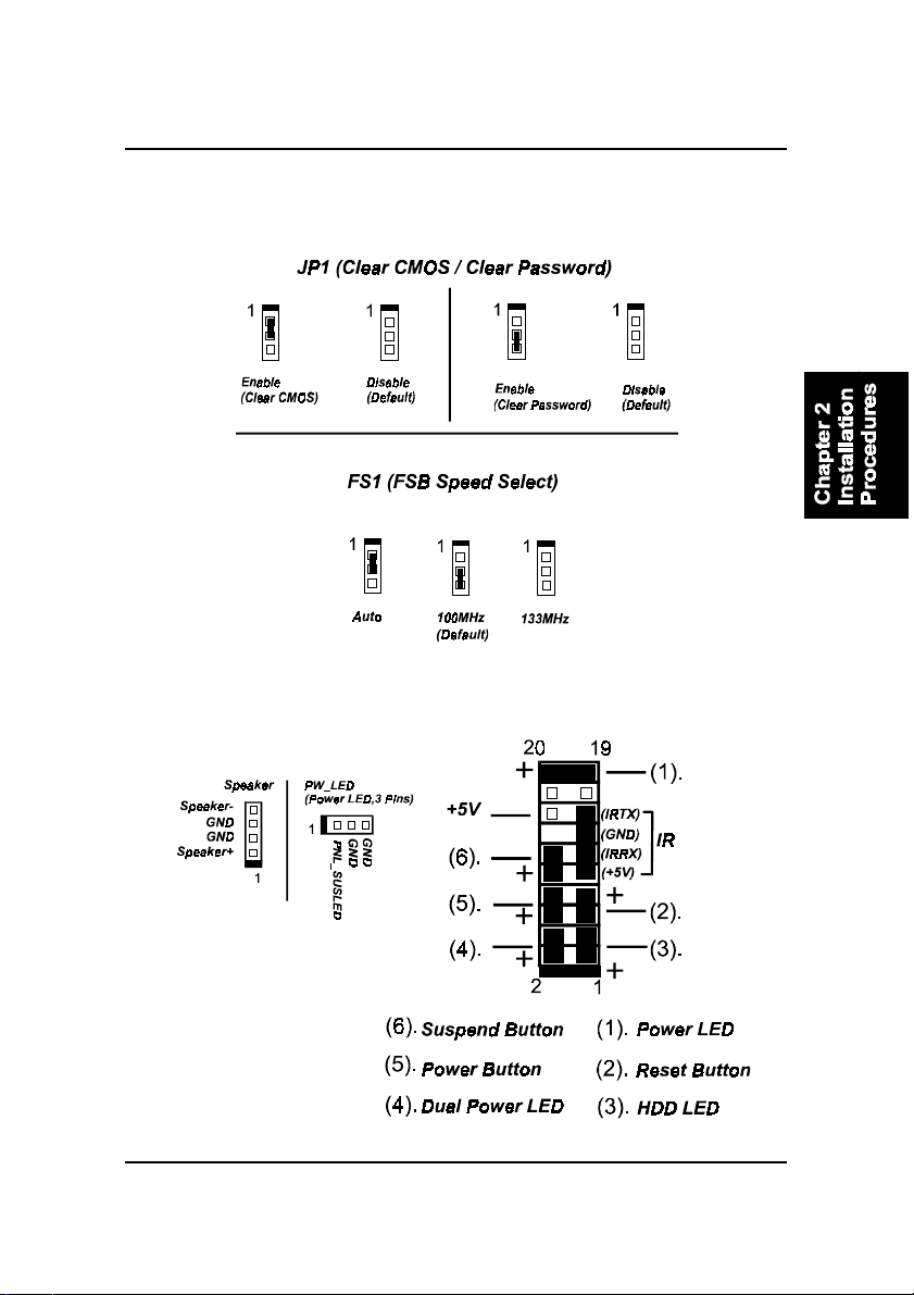
Front Panel Block, Power LED and Speaker Connector ..... 2-12
PS/2 Keyboard and Mouse Connector .............................. 2-13
Optional LAN Connector .................................................. 2-14
Universal Serial Bus Connectors ....................................... 2-14
Serial Port Connectors ....................................................... 2-15
Printer Connector .............................................................. 2-15
Audio I/O Jacks ................................................................ 2-16
Game/MIDI Connector ...................................................... 2-16
Chapter 3 BIOS Setup
CMOS Setup Utility ....................................................................... 3-1
Standard CMOS Setup ................................................................... 3-2
Advanced BIOS Features .............................................................. 3-4
Advanced Chipset Features .......................................................... 3-7
Integrated Peripherals .................................................................... 3-9
Power Management Setup ............................................................. 3-14
PnP/PCI Configurations ................................................................. 3-18
PC Health Status ............................................................................ 3-19
Frequency/Voltage Control ............................................................ 3-20
Load Fail-Safe Defaults .................................................................. 3-21
Load Optimized Defaults ................................................................ 3-21
Supervisor/User Password ............................................................ 3-21
Save and Exit Setup ....................................................................... 3-22
Exit without Saving ........................................................................ 3-22

1 - 1
Overview
Overview
Chapter 1
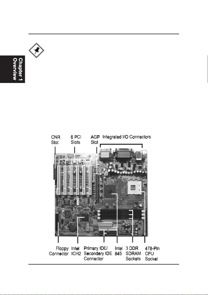
The new ATX, 478-pin 1stMainboard®VC15 supports a full range of the latest
generation Intel®Pentium®4 processors. The leading edge chipset Intel®845
MCH was designed for coworking with Pentium®4 (up to 2GHz) and
Northwood®processor (min 2GHz) in the 478-pin package based on the VRM
9.0 spec and 400MHz.Built using the leading edge technology the Intel
Pentium®4 processors provide a significant performance over previous
Pentium®III processors. Three (DDR 266MHz) PC-2100 SDRAM sockets al-
low for up to 2GB memory capacity. Support for the Ultra DMA/100protocol
and its high-speed interface further ensures that data transfer speeds are im-
proved, especially for long sequential transfers required by audio/visual ap-
plications. The board also features onboard audio and optional onboard LAN
function.
The 1stMainboard VC15 comes with a versatile range of I/O features such as
2 serial ports, 1 parallel port, 1 optional LAN, 1 PS/2 mouse and keyboard
connector, 4 USB connectors, 1 media connector (front audio, Line-in, Line-
out and Mic-in, game/MIDI port). Ample expansion is available through 6 PCI,
1AGP (only 1.5V 4X cards allowed) and 1 CNR to meet the requirement for
enjoying the P4 CPU benefits in internet applicatons, video/3D graphics per-
formance, and so forth. Other key features are Remote On/Off, Auto Power
Failure Recovery, integrated temperature monitoring and system fan control.
Included also is CD Pro with enhanced drivers and the new CD Plus package
containing a few bundled soft-ware solutions such as Norton®AntiVirus,
Norton Ghost, Norton Virtual Drive.
Package Checklist
If you discover any item below was damaged or lost, please contact your
vendor.
þThe mainboard þThis user manual
þOneFDDcable þOne HDD cable
þOneATA/100cable þ Two software CDs (CD Pro, CD Plus)
1 - 2
VC15MainboardManual
The VC15 Mainboard
NOTE: CD Pro that contains patch files, onboard video/audio chip
drivers, related online help and other useful information can be
found in your mainboard package.
Please install it right after your Windows operating system installa-
tion is done.
Place your CDPro in the drive, an operating menu will
appears in your monitor. Please select
Auto Installation
. It will auto-
matically detect which software tools (patch files, drivers) that the
mainboard needs. Press OK button to go through the whole instal-
lation procedure in a very straight forward and easy way. It also
provides you with a custom way to select wanted patch files and
software drivers that for onboard chips use. The top menu of the
CD Pro lists all the functions that allowed by this board.

1 - 3
Overview
Main Features
nEasy Installation
||BIOS with support for Plug and Play, auto detection of IDE hard drives,
||LS-120|drives, IDE ZIP drives, Windows 98SE, Windows ME, Windows
||NT, Windows 2000, Windows XP, and OS/2.
nLeading Edge Chipset
Intel®845 provides integrated DRAM controllers with new Dynamic
Power Management Architecture (DPMA), concurrent PCI, AGP and USB.
The built-in audio and vedio features of the Intel chipset 845 (MCH +
ICH2) provide better visual performance with the Dynamic Video Memory
Technology (DVMT) properties.
nVersatile Main Memory Support
Accepts up to 2 GB DDR SDRAM using thiree memory sockets for allow-
ing that from 64, 128, 256, 512MB with support for lightenning-fast PC-
2100 DDR SDRAM (266 MHz).
nCNR, AGP, and PCI Expansion Slots
One CNR, one AGP Bus expansion slot (only 1.5V 4X card allowed), and
six PCI Bus expansion slots provided the room to install a full range of
add-on cards.
nOnboard IrDA Connector
An IrDA port integrated with front panel block connector for wireless
infrared connections is available.
nFlexible Processor Support
Onboard CPU 478-pin socket supports:
Intel®Pentium 4 processor 1.4 GHz - 2.0 GHz and up*
/ Intel®Northwood processor*. (*: not test yet)
nSuper Multi Input/Output (I/O) Support
Integrated Plug and Play multi-I/O chipset features two high-speed UART
16550 compatible serial ports, one EPP/ECP capable parallel port, one
game port, and one FDD connector.

1 - 4
VC15MainboardManual
nIntegrated Audio Subsystem
Embedded audio features in the ICH2 with an integrated PCI audio con-
troller, DOS games compatible engine. The subsystem utilizes line-out,
line-in, and MIC external jacks, one joystick port with MIDI interface.
nOnboard Accelerated Graphics Port (AGP)
The motherboard is installed one 32-bit 1.5V AGP 4X bus with a dedi-
cated 66MHz/133MHz path from the graphics card to the system memory
offering much greater bandwidth than the 32-bit PCI bus does. AGP en-
abled 3D graphics cards can directly access main memory across this fast
path instead of using local memory.
nEnhanced PCI Bus Master IDE Controller with Ultra DMA 33/66/100
Support
Integrated Enhanced PCI Bus Master IDE controller features two dual-
channel connectors that up to four Enhanced IDE devices, including CD-
ROM and Tape Backup Drives, as well as Hard Disk Drives supporting
the new Ultra DMA 100 protocol. Standard PIO Mode 3, PIO Mode 4,
DMA Mode 2, DMA Mode 4, UltraDMA-100 Mode 5 devices are also
supported.
nConvenient Rear Panel USB Connection Support
Two USB ports integrated in the rear I/O panel and two extra USB ports for
either front or rear panel connection allow convenient and high-speed
Plug and Play connections to the growing number of USB compliant
peripheral devices on the market.
nLAN Support (optional)
Onboard optional LAN controller with one optional jack integrated with
other rear panel I/O connectors pvovides users with a convenient con-
nection with network environment.

1 - 5
Overview
FIC Unique Innovation for Users (NOVUS) -
Enhanced Mainboard Features and System Support
nLogoGenie
A user friendly GUI supporting Windows 95/98/98SE (not Windows 2000/
NT/ME), LogoGenie allows you to customize, create or select a Logo
which will be displayed when the system is booting.
NOTE:
1. LogoGenie supports Award BIOS only.
2. If you create a Logo file (.bmp) by LogoGenie, the file size must
||||be 640 x 464 x 256 colors.
To enable this utility, please proceed as follows:
1. Insert CD Pro. Select LogoGenie from the Menu and
follow the installation instructions.
2. After LogoGenie has been installed, go to Windows Start Box.
In Programs Menu, select LogoGenie (ver.), then select LogoGenie.
3. Press F1 to read Help file to understand how to use this software if
it is new to you.
nBIOS Guardian
BIOS Guardian by default is enabled. It must be disabled in order to
reflash BIOS, thus effectively acts as a fire-wall against viruses that can
attack the BIOS while the system is running.
WARNING: While excute Step3 below, please do not turn off the
sytsem power in order to avoid BIOS damage.
BIOS Guardian can be disabled as follows:
1. Go to BIOS Set Up Menu. (Press Del key while booting.)
2. Go to Advanced BIOS Features Set Up Submenu.
3. Disable BIOS Guardian.
4. Save the setting, and restart system.

1 - 6
VC15MainboardManual
nOverclock Partner
Should the system not start because clock speed settings have been
increased to a speed incompatible with the system, the Overclock Partner
allows you to reboot at system default settings, protecting hardware from
any damages.
Complete the following steps:
1. Turn the system off.
2. Restart while holding down the Insert key. It is important that the
Insert key is held down until the default clock speed is shown on
the POST screen.
3. Enter BIOS settings menu, and re-set clock speed desired or default.
nEasy Key
Instead of completing the multi-layered BIOS setup process these 3 Easy
Key functions provide direct access to Sub-Menus when completing
BIOS settings adjustments.
Easy-Keys are as follows:
Ctrl + c: To enter clock settings menu.
Ctrl + p: To load Performance Default settings and restart.
Ctrl + f: To load Fail-Safe Default settings and restart.
NOTE: However, if it is disabled and while boot the system, the
POST screen will be held and shows you the message to let you
know the current status of BIOS Guardian. To press G key will en-
able the BIOS Guardian again; or simply to press the space bar
will continue the booting process.

2 - 1
Installation Procedures
Chapter 2
Installation Procedures
The mainboard has several user-adjustable jumpers on the board that allow you to
configure your system to suit your requirements. This chapter contains information
on the various jumper settings on your mainboard.
To set up your computer, you must complete the following steps:
nStep 1 - Set system jumpers
nStep 2 - Install memory modules
nStep 3 - Install the Central Processing Unit (CPU)
nStep 4 - Install expansion cards
nStep 5 - Connect ribbon cables, cabinet wires, and power supply
nStep 6 - Set up BIOS software
nStep 7 - Install supporting software tools
WARNING: Excessive torque may damage the mainboard. When
using an electric screwdriver on the mainboard, make sure that
the torque is set to the allowable range of 5.0 ~ 8.0kg/cm.
Mainboard components contain very delicate Integrated Circuit
(IC) chips. To prevent static electricity from harming any of the
mainboard’s sensitive components, you should follow the
following precautions whenever working on the computer:
1. Unplug the computer when working on the inside.
2. Hold components by the edges and try not to touch the IC
||||chips, leads, or circuitry.
3. Wear an anti-static wrist strap which fits around the wrist.
4. Place components on a grounded anti-static pad or on the bag
that came with the component whenever the components are
separated from the system.
2 - 2
VC15MainboardManual
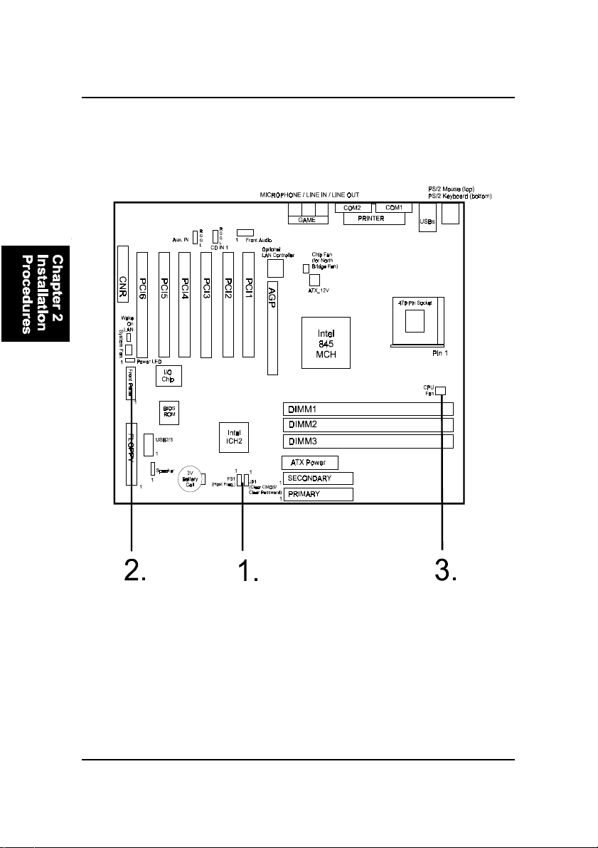
Mainboard Layout
Quick Reference (from Page 2-2 to 2-4)
2 - 3
Installation Procedures
1). Clear CMOS, Clear Password,
FSB Speed Select
2). Front Panel Block Cable Connection
2 - 4
VC15MainboardManual
1). Set System Jumpers
NOTE: Users are not encouraged to change the jumper/switch set-
tings not listed in this manual. Changing the settings improperly
may adversely affect system performance.
3). CPU Fan Installation
This connector is linked to the CPU fan. When the system is in some power saving
mode, the CPU fan will turn off; when it reverts back to full on mode, the fan will turn
back on. Without sufficient air circulation, the CPU may overheat resulting in
damage to both the CPU and the mainboard.
Damage may occur to the mainboard and/or the CPU fan if these pins are
used incorrectly. These are not jumpers, do not place jumper caps over these
pins.
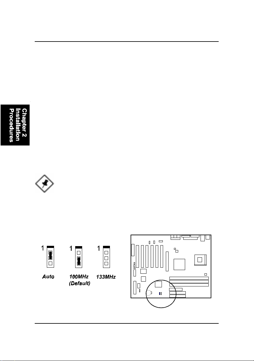
FSB Speed Select: FS1
The jumper allows you to select the host frequency of your mainboard.
2 - 5
Installation Procedures
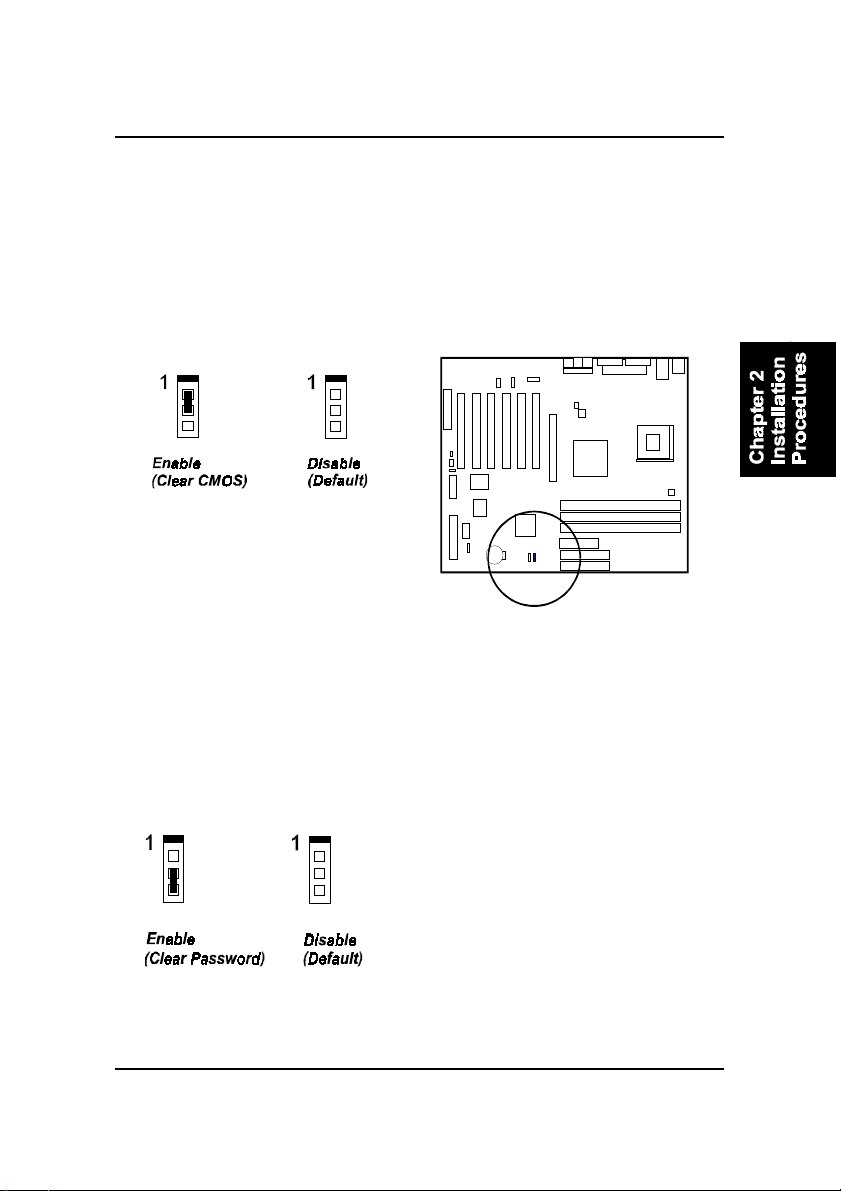
Clear Password: JP1
This jumper allows you to enable or disable the password configuration. You
may need to enable it if you forget your password. To clear the password
setting: (1) Turn off your computer. (2) Move the jumper cap pinpair 2-3. (3)
Turn on your computer. (4) Hold down the Delete key during bootup and enter
BIOS Setup to re-enter user preferences. (5) Turn off your computer, (6) Re-
move the jumper cap to disable this function. (7) Turn on your computer for
the new settings to take effect.
Clear CMOS: JP1
The CMOS RAM is powered by the onboard button cell battery. To clear the
RTC data: (1) Turn off your computer. (2) Place the jumper cap onto the pinpair
1-2 to clear CMOS. (3) Turn on your computer until CMOS checksum error
appears. (4) Turn off your computer. (5) Take off the jumper cap to disable it.
(6) Turn on your computer. (7) Hold down the Delete key when boots. (8) Enter
the BIOS Setup to re-enter user preferences.
2 - 6
VC15MainboardManual
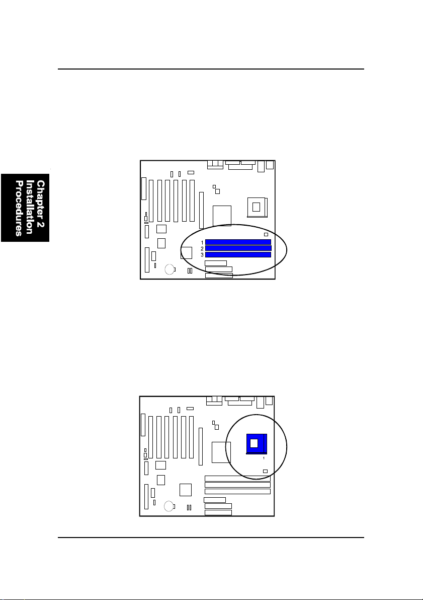
3). Install the CPU
The mainboard has built-in Switching Voltage Regulator to support CPU Vcore
autodetection. That is, It has the ability to detect and recognize the CPU
voltage, clock, ratio and enables users to set up the CPU frequency from the
BIOS Setup Screen. Users can adjust the frequency through Frequency /
Voltage Control of the BIOS Setup Screen.
Press the clips with both hands to remove the DIMM.
2). Install Memory Modules
1. Locate the DIMM slots on the mainboard.
2. Install the DIMM straight down into the DIMM slot using both hands.
3. The clip on both ends of the DIMM slot will close up to hold the DIMM
in place when the DIMM reaches the slot bottom.

2 - 7
Installation Procedures
To install the CPU, do the following:
1. Lift the lever on the side of the CPU socket.
2. Handle the chip by its edges and try not to touch any of the pins.
3. Place the CPU in the socket. Do not force the chip. The CPU should slide
easily into the socket.
4. Swing the lever to the down position to lock the CPU in place.
5. Place the cooling fan with heatsink on top of the installed CPU.
When you install the CPU on this mainboard, please use a power supply that
designed and manufactured only for your CPUs use. Your CPU fansink com-
bined with its retention module must be completely closed and firmly attached
on the top of the processor.
NOTE: Users The CPU installing procedures should be:
1. Insert the CPU (with its fansink and retention module) on the
socket.
2. Connect the 20-pin plug of the power supply
3. Connect the 4-pin plug of the power supply.
To remove the processor, please do it in reverse order.
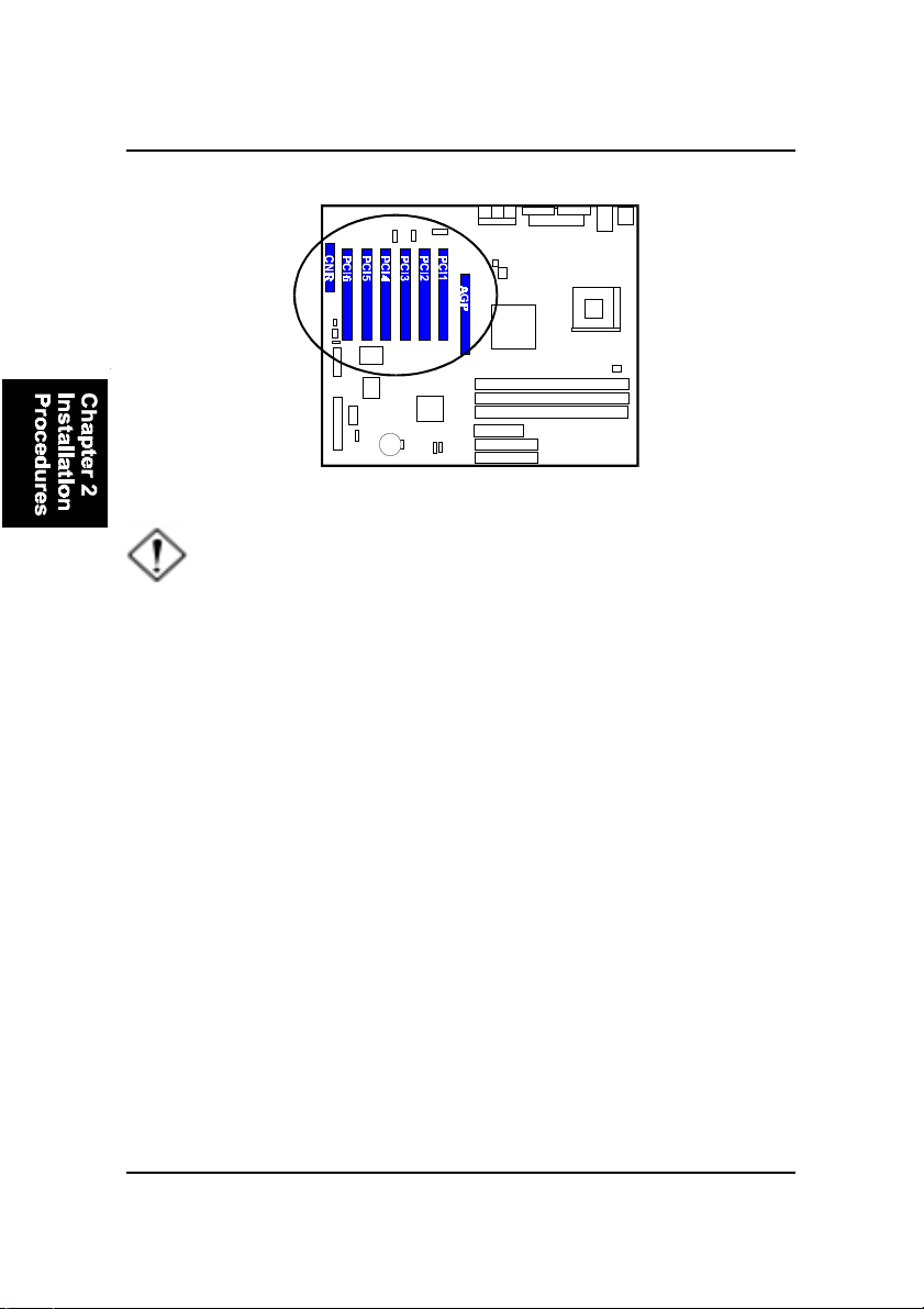
4). Install Expansion Cards
This section describes how to connect an expansion card to one of your
system expansion slots. Expansion cards are printed circuit boards that, when
connected to the mainboard, increase the capabilities of your system. For
example, expansion cards can provide video and sound capabilities. The
mainboard features one CNR, one AGP, and six PCI bus expansion slots.
2 - 8
VC15MainboardManual
CAUTION: Make sure to unplug the power supply when adding or
removing expansion cards or other system components. Failure to
do so may cause severe damage to both the mainboard and
expansioncards.
Always observe static electricity precautions.
Please read Handling Precautions at the start of this manual.
This mainboard supports 1.5V AGP 4X card only; other type cards
may damage card and mainboard.
To install an expansion card, follow the steps below:
1. Remove the computer chassis cover and select an empty expansion
slot.
2. Remove the corresponding slot cover from the computer chassis.
Unscrew the mounting screw that secures the slot cover and pull
the slot cover out from the computer chassis. Keep the slot cover
mounting screw nearby.
2 - 9
Installation Procedures
5. Secure the board with the mounting screw removed in Step 2. Make
sure that the card has been placed evenly and completely into the
expansion slot.
6. Replace the computer system cover.
7. Setup the BIOS if necessary.
8. Install the necessary software drivers for the expansion card.
3. Holding the edge of the peripheral card, carefully align the edge
connector with the expansion slot.
4. Push the card firmly into the slot. Push down on one end of the
expansion card, then the other. Use this rocking motion until the add
on card is firmly seated inside the expansion slot.
5). Connect Devices
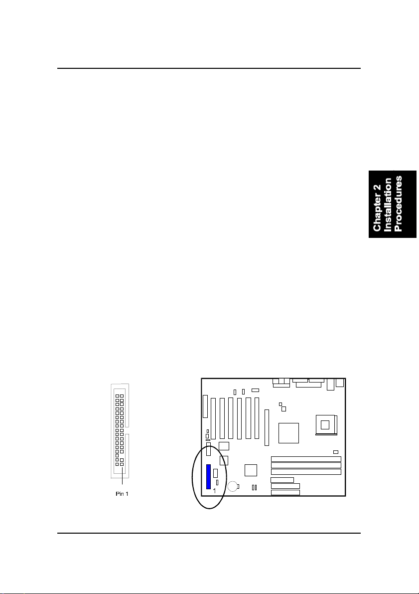
Floppy Diskette Drive Connector
This connector provides the connection with your floppy disk drive.
The red stripe of the ribbon cable must be the same side with the Pin 1.
2 - 10
VC15MainboardManual
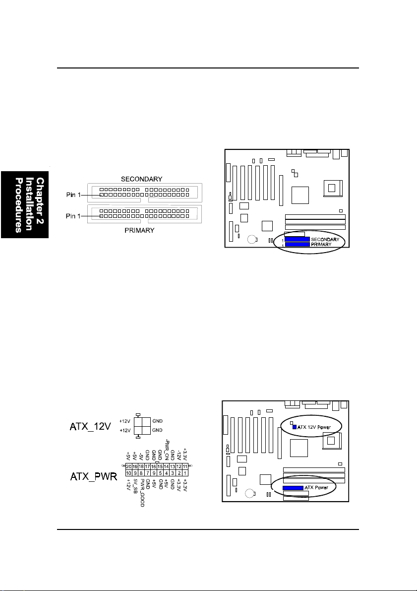
Power Connectors
The 20-pin male block connector is connected to the ATX power supply. The
neighboring socket is for the auxiluary power plug use. The 4-pin male block
connector is for the 12V power use. All the three connectors are linked with
your ATX power supply. The plug from the power supply will only insert in
one orientation because of the different hole sizes. Find the proper orientation
and push down firmly making sure that the pins are aligned.
IDE Device Connectors
These two connectors are used for your IDE hard disk drives, CD drives, LS-
120|drives, or IDE ZIP drives. The red stripe of the ribbon cable must be the
same side with the Pin 1.
Table of contents
Other FIC Motherboard manuals


