FIC CW33 User manual

CW33
CW33+
MAINBOARD
MANUAL
DOC No.: M99301
Rev. :A0
Date : 6, 1999
Part No. : 25-10962-20

i
Tableof Contents
Table of Contents
Chapter 1 Overview
CW33 Mainboard .......................................................................... 1-1
CW33+Mainboard ........................................................................ 1-2
Package Checklist .......................................................................... 1-2
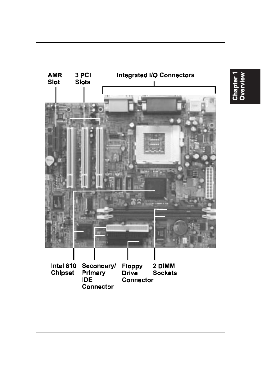
The Mainboard .............................................................................. 1-3
Main Features................................................................................ 1-4
Intelligent Properties...................................................................... 1-6
ACPIReady ................................................................................... 1-7
Chapter 2 Installation Procedures
1). Set System Jumpers .................................................................. 2-2
QuickReference............................................................................. 2-3
Mainboard Layout .................................................................... 2-7
Password Clearance Function: CLR_PSWD ..................... 2-9
CMOSClearanceFunction:CLR_CMOS .......................... 2-9
BIOSTop Block Lock Selection:TBL ................................ 2-9
System Bus Frequency Selection: FS1, FS2 ...................... 2-10
FrontPanelUSB Connector Selection: FNT_USB ............ 2-11
2). Install RAM Modules .............................................................. 2-11
RAM Module Configuration..................................................... 2-11
Install and Remove DIMMs ...................................................... 2-12
3).Installthe CPU .......................................................................... 2-13
4). Install Expansion Cards............................................................. 2-14
5). Connect Devices ....................................................................... 2-15
FloppyDiskette Drive Connector: FLOPPY ...................... 2-15
IDEHDD DeviceConnectors: PRIMARY,SECONDARY .. 2-16
ATX Power Connector:POWER ....................................... 2-17
CPUFan Connector:CPU_FAN ........................................ 2-17
System Case Fan Connector: CHS_FAN........................... 2-17
Wake-On-Ring Connector: WOR ...................................... 2-18
Wake-On-LAN Connector: WOL ...................................... 2-19
InfraredConnector:IR....................................................... 2-19
CDAudio-Out Connectors: CD_IN1, CD_IN2 .................. 2-19
TVVideo Port Connector:RGB_OUT ............................... 2-20
FrontPanel Block Connector: F_PNL ............................... 2-20
Video Graphics AcceleratorConnector: VGA ................... 2-21
PS/2 Keyboard and Mouse Connector: KB, MS ............... 2-22

ii
CW33/CW33+MainboardManual
UniversalSerial BusConnectors: FNT_USB,Back USBs . 2-22
PrinterConnector: LPT...................................................... 2-23
SerialPort Connectors: COM1, COM2 .............................. 2-23
Joystick/MIDIConnector:GAME..................................... 2-24
AudioI/O Jacks:LINE_OUT, LINE_IN,MIC_IN .............. 2-24
Chapter 3 BIOS Setup
Chapter 4 FAQs
GeneralFAQs................................................................................. 4-1
BIOSFAQs .................................................................................... 4-5
Windows 98 FAQs ......................................................................... 4-7
Windows 95 FAQs ......................................................................... 4-8
IntelCPU FAQs ............................................................................. 4-9

1 - 1
Overview
Overview
Chapter 1
CW33 Mainboard
The1stMainboard CW33 is a microATX sized Socket 370 Mainboard support-
ingthe Intel® Celeron™ PPGA 300A-500 MHz processor. A highly integrated
and feature rich Mainboard it offers the very latest in cutting edge onboard
features.Based around theadvancedarchitecture of thenew Intel® 810 chipset,
the 1stMainboard CW33 is equipped with high quality onboard audio and
video capabilities.
The onboard video function benefits significantly from the state of the art
Dynamic Video Memory Technology (DVMT), which ensures more efficient
use of the system memory. The DVMT feature builds upon AGP technology
to automatically size video memory to meet the appropriate functional and
performance requirements of any application.
With the advanced new Suspend to RAM function (must run an operating
system which allows ACPI, such as Windows 98), all data is stored to the
DRAM when the system goes to suspend mode- greatly reducing the system’s
power consumption. When the system is woken from the suspend mode, all
data is instantly available, meeting the user-friendly requirements of the
1stMainboard Instantly Available PC. The CW33 also supports the Ultra
DMA33/66* protocol and its high-speed interface, which significantly im-
proves hard drive performance and data transfer speeds. This is especially the
case for long sequential data transfers typically associated with audio/visual
applications.
The 1stMainboard CW33 boasts a complete range of standard I/O connec-
tions including the new Audio Modem Riser Card connection, TV-Out pin-
header, Digital Flat Panel pin header, VGA connector and Media connector.
Other advanced features include Auto Power Failure Recovery and Keyboard/
Mouse Power On. The 1stMainboard CW33 has 3 PCI expansion slots, 2
DIMM for up to 512 MB of SDRAM, and is PC98 and Y2K compliant. The
1stMainboard CD Pro provides users with easy ‘one-touch’ access to the
latest advanced onboard drivers.

1 - 2
CW33/CW33+MainboardManual
Package Checklist
If you discover any item below was damaged or lost, please contact your
vendor.
Ö Themainboard
Ö Thisuser manual
Ö Onefloppy disk driveribboncable
Ö OneIDEribbon cable
Ö Software utilities
The 1stMainboard CW33+ is a microATX sized Socket 370 Mainboard sup-
porting the Intel® Celeron™ PPGA 333-500 MHz processor. A highly inte-
grated and feature rich Mainboard it offers the very latest in cutting edge
onboard features. Based around the advanced architecture of the new Intel®
810 chipset, the 1stMainboard CW33+ is equipped with high quality onboard
audio and video capabilities. Onboard video comes with an impressive 4 MB
display cache. With the advanced newSuspend to RAM function (must run an
operating system which allows ACPI, such as Windows 98), all data is stored
to the DRAM when the system goes to suspend mode- greatly reducing the
system’s power consumption. When the system is woken from the suspend
mode, all data is instantly available, meeting the user-friendly requirements of
the 1stMainboard Instantly Available PC. The CW33+ also supports the Ul-
tra DMA/66 protocol and its high-speed interface, which significantly im-
proves hard drive performance and data transfer speeds. This is especially the
case for long sequential data transfers typically associated with audio/visual
applications.
The 1stMainboard CW33+ boasts a complete range of standard I/O connec-
tions including the new Audio Modem Riser Card connection, TV-Out pin-
header, Digital Flat Panel pin header, VGA connector and Media connector.
Other advanced features include Auto Power Failure Recovery and Keyboard/
Mouse Power On. The 1stMainboard CW33+ has 3 PCI expansion slots and
one AMR slot, 2 DIMM for up to 512 MB of SDRAM, and is PC98 and Y2K
compliant. The 1stMainboard CD Pro provides users with easy ‘one-touch’
access to the latest advanced onboard drivers.
CW33+ Mainboard
1 - 3
Overview
The Mainboard

1 - 4
CW33/CW33+MainboardManual
Main Features
■Easy Installation
||BIOS with support for Plug and Play, auto detection of IDE hard drives,
||LS-120|drives,IDE ZIP drives, Windows 95, Windows98,WindowsNT,
||andOS/2.
■Leading Edge Chipset
Intel 810 chipset includes a CPU interface controller, integrated memory
controller, integrated power management unit, concurrent PCI (PCI v.2.0,
2.1,2.2), 3D video, IDE and ISA bus controller.
■Flexible Processor Support
Onboard Socket 370 supports leading-edge processors:
Celeron™PPGA processors 333/366/400/433/466/500MHz and up.
|■Various External Bus and CPU/Bus Frequency Ratio Support
The board supports the Bus frequency of 66 / 75 / 83 / 90 / 95 / 100 / 112
/124 /133MHz and theCPU/Bus frequency ratioof 2x/ 2.5x /3x / 3.5x/ 4x
/ 4.5x / 5x / 5.5x / 6x / 6.5x / 7x / 7.5x / 8x by a switching voltage regulator
whichaccepts 1.8V to 2.8V.|||(Please read InstalltheCPU in Chapter 2for
moreinformation).
■Versatile Main Memory Support
Acceptsup to 512MB (total)RAM using two DIMMs of8, 16, 32, 64,128,
256MBwith support for lightning-fast SDRAM (66/100MHz).
■PCI Expansion Slots and AMR Slot
Three 32-bit PCI Bus expansion slots provide the room to install a full
range of add-on cards and an AMR slot for modem riser card.
■Onboard IrDA Connector
An IrDA connector for wireless infrared connections is available.

1 - 5
Overview
■Enhanced PCI Bus Master IDE Controller with Ultra DMA/33 and Ultra
|||||||||DMA/66Support (CW33 optionalsupport)
Integrated Enhanced PCI Bus Master IDE controller features two dual-
channel connectors that accept up to four Enhanced IDE devices, includ-
ing CD-ROM and Tape Backup Drives, as well as Hard Disk Drives sup-
porting the new Ultra DMA/66 protocol (CW33 optional support). Stan-
dard PIO Mode 3, PIO Mode 4, DMA Mode 2/4 devices are also sup-
ported.
■USB Support
Two USB jackss for rear panel connection and one pinhead for front
panel connection provide you with convenient, high-speed Plug and Play
connections (up to four USB ports) to the growing number of USB com-
pliant external peripheral devices on the market.
■■
■■
■Remote Wake-Up Support
One LAN wake-up connector, WOL, supports LAN cards equipped for
remote wake-up functionality; also, an additional Wake-On-Ring connec-
tor, WOR, awakes the system while the ring signal via modem.
■■
■■
■Super Multi Input/Output (I/O) Support
IntegratedPlug and Play multi-I/O chipset features two high-speed UART
16550 compatible serial ports, one IR connector, one EPP/ECP capable
parallel port, and one FDD connector.
■■
■■
■Compact ESS Solo-1 Audio Subsystem for Sound and Game (optoinal)
The onboard audio provides DirectMusic accelerator. It also provides
OPL3,Sound Blaster Pro,MPU401 UART mode andJoystick function for
various PC games on real DOS mode that without software drivers. The
board came with three audio jacks: MIC_IN, LINE_IN, LINE_OUT; and
one connector for joystick with MIDI interface.
■■
■■
■Advanced Suspend to RAM Function for Saving Power Consumption
If your operating system supports ACPI, such as Windows 98, this fea-
ture allows all data to be kept in the DRAM to make sure all data instantly
available for reducing the system power consumption.

1 - 6
CW33/CW33+MainboardManual
Intelligent Properties
This mainboard comes equipped with the most advanced new features that
not only optimize the performance of the latest processors but also enhance
the manageablity, power management capabilities, and user-friendliness of
your system. This section provides detailed information on these features,
and how they are implemented on the mainboard.
■■
■■
■Advanced Multi-Media Properites of Intel 810 Chipset
The built-in audio and vedio features of the Intel chipset 810 on the
mainboard CW33 and CW33+ (with 4MB display cache) provides better
visualperformance withthe DynamicVideoMemoryTechnology (DVMT)
properties.
■■
■■
■OptimizedCeleronÔPPGAProcessor Performance
The mainboard utilizes the advanced features of the Intel 810 chipset to
optimize the unrivaled performance of the CeleronÔPPGA processor
with MMXÔtechnology, allowing you to enjoy a richer video, audio,
digitalimaging and communications experience from the latestgeneration
ofmultimedia software.
■Using TV as Monitor (optional)
The connector, RGB_OUT, makes use of a television as a monitor for
software games and other tasks by a cable from the mainboard to your TV.

1 - 7
Overview
ACPI Ready
Thismainboard fully implements the new ACPI (Advanced Configuration and
PowerInterface) 1.0Hardware andBIOS requirement.If youinstall ACPIaware
operating system, such as Windows 98, you fully utilized the power saving
under ACPI.
It is compatible with all other none ACPI operating systems. If you want to
setup ACPI feature under Windows 98, please follow the description below:
Run Windows 98 setup by using setup/p j on the command line for installing
Windows 98 with the ACPI control feature.
If you type setup without the parameter /p j, Windows 98 will be installed as
APM, PnP mode, no ACPI will be used.
For more detail information, please visit the web site of Microsoft. Its address
is:www.microsoft.com/hwtest/.
The major features of ACPI were listed as follows:
■Soft-Off Support
The mainboard’s Soft-Off feature allows you to turn off your computer
using the operating system. This feature requires a power supply witha
soft-off power controller.
■RemoteRing-On
The Remote Ring-On function allows your computer to be turned on
remotely via a modem while it is in sleep mode. This feature is particularly
usefully when you are expecting a fax late night and leave only your
modem on to minimize power consumption. As soon as possible the phone
rings, the modem automatically turn on the system, which answers the
phone and downloads the fax. Then the computer shuts off again, thereby
minimizing its consumption of power. The Remote Ring-On function
requires a power supply with a soft-off power controller.
■RTCAlarm
The RTC alarm feature allows you to preset the computer to wake-up at a
certaintime allowing you to implement a number of useful functions, such
as automatically sending out a fax late at night.

1 - 8
CW33/CW33+MainboardManual
This Page Left Blank for Note

2 - 1
Installation Procedures
Chapter 2
Installation Procedures
The mainboard has several user-adjustable jumpers on the board that allow you to
configure your system to suit your requirements. This chapter contains information
on the various jumper settings on your mainboard.
To set up your computer, you must complete the following steps:
■ Step 1 - Set system jumpers
■ Step 2 - Install system RAM modules
■ Step 3 - Install the Central Processing Unit (CPU)
■ Step 4 - Install expansion cards
■ Step 5 - Connect ribbon cables, cabinet wires, and power supply
■ Step 6 - Set up BIOS software (see Chapter Three)
■ Step 7 - Set up supporting software tools
WARNING: Excessive torque may damage the mainboard. When
using an electric screwdriver on the mainboard, make sure that
the torque is set to the allowable range of 5.0 ~ 8.0kg/cm.
Mainboard components contain very delicate Integrated Circuit
(IC) chips. To prevent static electricity from harming any of the
mainboard’s sensitive components, you should follow some
precautions whenever working on the computer:
1. Unplug the computer when working on the inside.
2. Hold components by the edges and try not to touch the IC
||||chips, leads, or circuitry.
3. Wear an anti-static wrist strap which fits around the wrist.
4. Place components on a grounded anti-static pad or on the bag
that came with the component whenever the components are
separated from the system.

2 - 2
CW33/CW33+MainboardManual
1). Set System Jumpers
Jumpers are used to select the operation modes for your system. Some jump-
ers on the board have three metal pins with each pin representing a different
function. A “1” is written besides pin 1 on jumpers with three pins. To set a
jumper, a black cap containing metal contacts is placed over the jumper pin/s
according to the required configuration. A jumper is said to beshorted when
the black cap has been placed on one or two of its pins. The types of jumpers
used in this manual are shown below:
NOTE: Users are not encouraged to change the jumper settings
not listed in this manual. Changing the jumper settings improperly
may adversely affect system performance.

2 - 3
Installation Procedures
This Chapter is intended to aid quick and easy installation.
In the event that more detailed information is required, please
consult the Installation Procedures Chapter.
2 - 4
CW33/CW33+MainboardManual

2 - 5
Installation Procedures
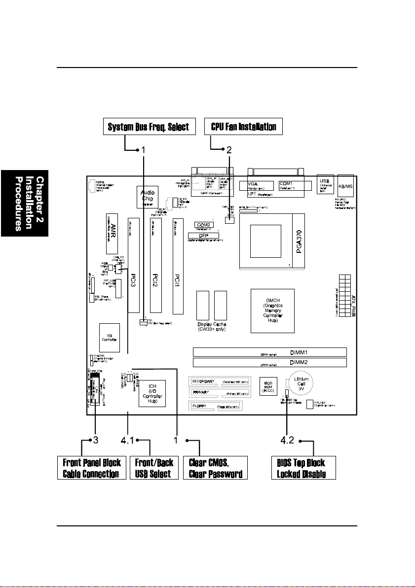
1). System Bus Frequency Select, CPU Ratio Select,
2). CPU Fan Installation
This connector is linked to the CPU fan. When the system is in suspend mode, the
CPU fan will turn off; when it reverts back to full on mode, the fan will turn back on.
Without sufficient air circulation, the CPU may overheat and cause damage to
both the CPU and the mainboard.
Damage may occur to the mainboard and/or the CPU fan if these pins are
incorrectlyused.Thesearenotjumpers,do not place jumper caps over these
pins.
3). Front Panel Block
Clear CMOS, Clear Password
Cable Connection

2 - 6
CW33/CW33+MainboardManual
5). Load BIOS Setup Default
Load Fail-Safe Defaults
BIOS defaults contain the most appropriate values of the system parameters
thatallow minimum system performance. The OEM manufacturermay change
the defaults through AMIBCP before the binary image burns into the ROM.
Load Optimized Defaults (recommended)
Selecting this field loads the factory defaults for BIOS and Chipset Features
which the system automatically detects.
1. Formata bootable system floppy diskette by typing the command format
a:/sin command mode.
2. Visit the the web site of the vendor and visit the BIOS Update page in the
related Technical Support section.
3. Select the BIOS file you need and download it to your bootable floppy
diskette.
4. Insert the bootable diskette containing the BIOS file into the floppy dis-
kette drive.
5. Assuming that the floppy diskette drive is A, reboot the system by using
the A: drive. At the A: > prompt, run the BIOS upgraded file by executing
the Flash BIOS utility and the BIOS file with its appropriate extension.
Do not turn off or reset the computer during the flash process or if there is
a problem.
6). How to Upgrade BIOS
4). Other Enabled/Disabled Jumpers
2 - 7
Installation Procedures
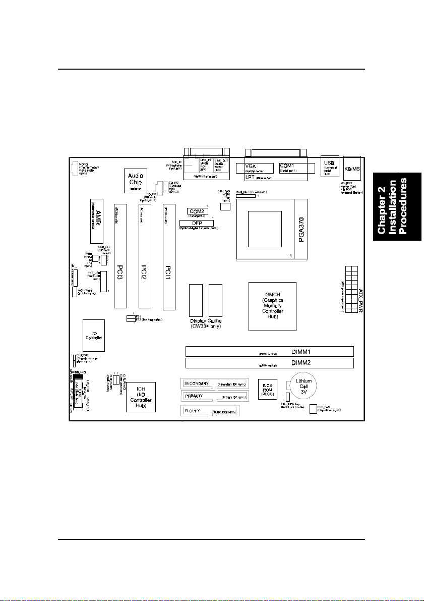
Mainboard Layout

2 - 8
CW33/CW33+MainboardManual
ONBOARDMARK MEANING PAGE
Jumpers
CLR_CMOS Clear CMOS Data 2 - 9
CLR_PSWD Clear Password 2 - 9
TBL BIOS Top Block Lock Select 2 - 10
FS1, FS2 System Bus Frequency Select 2 - 10
FNT_USB Front Panel USB Connector Select 2 - 11
Slots
DIMM1/2 DIMM Memory Module Support 2 - 12
PGA370 Celeron CPU Socket 2 - 13
AMR Audio Modem Riser Card Slot 2 - 14
PCI1/2/3 PCI Bus Expansion Slot (32-bit) 2 - 14
Connectors
FLOPPY Floppy Diskette Drive Connector 2 - 15
PRIMARY, SECONDARY IDE HDD Device Connectors 2 - 16
POWER ATX Power Connector 2 - 16
CPU_FAN CPU Fan Connector 2 - 17
CHS_FAN System Case Fan Connectors 2 - 17
WOR Wake on Ring Connector 2 - 18
WOL Wake on LAN Connector 2 - 18
IR Infrared Port Module Connector 2 - 19
CD_IN1/2 CD Audio-Out Connector 2 - 19
RGB_OUT TV Video Port Connector 2 - 20
F_PNL Connectors for Front Panel LEDs
and Switches on Front Panel 2 - 20
VGA VGA Connector 2 - 21
KB, MS PS/2 Keyboard and Mouse Connector 2 - 22
FNT_USB, Back USBs Universal Serial Bus Connectors 2 - 22
LPT Printer Connector 2 - 23
COM1/2 Serial Port Connector 2 - 23
GAME Joystick/MIDI Device Connector 2 - 24
LINE_OUT, LINE_IN,
MIC_IN Audio I/O Jacks 2 - 24

2 - 9
Installation Procedures
Password Clearance Function: CLR_PSWD
This jumper allows you to enable or to disable the password configuration.
You may need to enable this jumper by shorting it with a jumper cap if you
forget your password. To clear the password setting: (1). Turn off your com-
puter, (2). Set the jumper to Enable, (3). Turn on your computer after booting,
(4). Turn off your computer, (5). Turn on your computer for the new settings to
take effect.
CMOS Clearance Function: CLR_CMOS
The CMOS RAM is powered by the onboard button cell battery. To clear the
RTC data: (1). Turn off your computer, (2). Move this jumper to Enable, (3).
Move the jumper back to Disable, (4). Turn on your computer, (5). Hold down
the Delete key during boot and enter BIOS Setup to re-enter user preferences.
This manual suits for next models
1
Table of contents
Other FIC Motherboard manuals


