FIC KT-400A User manual

KT-400A / KT-600
Dynasty
MAINBOARD
MANUAL
KT-400A
KT-400A Pro
KT-600 Pro
DOC No.: M03208/M032A8/M03503
Rev. : A1
Date : 8, 2003
Part No. : 25-11705-01

i
Table of Contents
Table of Contents
Chapter 1 Overview
Package Checklist .......................................................................... 1-2
KT-400APro / KT-400A/ KT-600 Pro ........................................ 1-3
Main Features................................................................................ 1-4
FIC Unique Innovation for Users (NOVUS) -
Enhanced Mainboard Features and System Support ..................... 1-6
Chapter 2 Installation Procedures
1). Set System Jumpers .................................................................. 2-2
ClearCMOS ...................................................................... 2-2
BIOSAnti-Reflash Protect................................................. 2-3
FSB Frequency Select ....................................................... 2-3
2). Install Memory Modules .......................................................... 2-4
3). Install the CPU .......................................................................... 2-4
Connect ATX Power.......................................................... 2-6
4). Install Expansion Cards ............................................................. 2-7
5). ConnectDevices ....................................................................... 2-9
Floppy Diskette Drive Connector ...................................... 2-9
IDEDevice Connectors ..................................................... 2-9
Fan Connectors ................................................................. 2-10
Power Connectors ............................................................. 2-10
Front Panel Block, Power LED, IR, and Speaker Connector 2-10
SPDIF_OUT Connector .................................................... 2-12
SerialATAConnectors (KT-600 Pro only) ......................... 2-12
CDAudio-In Connectors................................................... 2-13
1394 Connectors (optional) ............................................... 2-13
PS/2 Keyboard and Mouse Connector.............................. 2-14
RJ45 LAN Connector ........................................................ 2-14
Serial Port Connectors....................................................... 2-15
Printer Connector .............................................................. 2-15
Audio I/O Jacks ................................................................ 2-16
Front Audio Connector ..................................................... 2-16
Universal Serial Bus Connectors....................................... 2-17

ii
KT-400A/KT-600Dynasty Mainboard Manual
Chapter 3 BIOS Setup
CMOS Setup Utility ....................................................................... 3-1
Standard CMOS Setup ................................................................... 3-2
Advanced BIOS Features .............................................................. 3-4
Advanced Chipset Features .......................................................... 3-8
Integrated Peripherals.................................................................... 3-11
Power Management Setup ............................................................. 3-15
PnP/PCI Configurations................................................................. 3-19
PC Health Status ............................................................................ 3-21
Frequency/Voltage Control ............................................................ 3-22
Load Fail-SafeDefaults .................................................................. 3-22
Load OptimizedDefaults ................................................................ 3-22
Supervisor/User Password ............................................................ 3-23
Save and Exit Setup........................................................................ 3-23
Exit without Saving ........................................................................ 3-23

1 - 1
Overview
Overview
Chapter 1
This new mainboard is an ATX sized board supporting the latest generation of
AMD®processors at industry leading speeds. By utilizingDDR (Double Data
Rate) transfer rate of the system bus effectively reaches Front Side Bus speeds
in 200/266/333MHz (KT-600 Pro reaches 400MHz.)As to system memory, it is
uptoDDR333(KT-600ProtoDDR400)MHzandhas3PC2100/PC2700/PC3200*
DIMMs for up to 3GB. The board provides users with an ATA133 data trans-
action for peripheral IDE drives .
(*: If you use PC3200 DDR DIMM, only DIMM1/2 socket is allowed.)
The board is based upon the high performance VIAKT400A(KT-400A Pro
and KT-400A) / KT600A(KT-600 Pro) as North Bridge and the VIA
VT8235CE(KT-400APro) / VT8235CD(KT-400A) /VT8237 (KT-600
Pro) as South Bridge. ItsAGP functions supported AGP 3.0 interface and the
most robust 3D games with software environments. The AGP slot onboard
accepts 4X/8X AGP card.
The board comes with a versatile range of I/O features such as 2 serial ports, 1
parallel port, 1 LAN, 2 optional IEEE 1394, 1 PS/2 mouse and keyboard connec-
tor, 6 USB ports (KT-600 Pro has 8 USB ports and two SATA connectors), 1
media connector (front audio, Line-in, Line-out and Mic-in). In addition, the
board is equipped with 2 dual channel enhanced PCI bus master IDE connectors.
Ample expansion is available through 5 PCI and 1AGP to meet the requirement
for enjoying the CPU benefits in internet applicatons, video/3D graphics per-
formance, and so forth.
Other key features are Remote On/Off, Auto Power Failure Recovery, inte-
grated temperature monitoring and system fan control. Included also is lst
Utilities CD with enhanced drivers and a few bundled soft-ware solutions.

1 - 2
KT-400A/KT-600Dynasty Mainboard Manual
NOTE: lst Utilities CD that contains patch files, onboard video/au-
dio chip drivers, related online help and other useful information
can be found in your mainboard package.
Please install it right after your Windows operating system installa-
tion is done.Place your lst Utility in the drive, an operating menu will
appears in your monitor. Please select Auto Installation. It will auto-
matically detect which software tools (patch files, drivers) that the
mainboard needs. Press OK button to go through the whole instal-
lation procedure in a very straight forward and easy way. It also
provides you with a custom way to select wanted patch files and
software drivers that for onboard chips use. The top menu of lst
Utilities lists all the functions that allowed by this board.
Package Checklist
If you discover any item below was damaged or lost, please contact your
vendor.

1 - 3
Overview
KT-400A Pro / KT-400A / KT-600 Pro

1 - 4
KT-400A/KT-600Dynasty Mainboard Manual
Main Features
CPU
KT-400A Pro and KT-400A
support AMDCPU FSB 200/266/333MHz -
AthlonXP : |||||1500+ to 3000+,
Athlon:|||||||||||||||900MHz to1.4GHz
Duron:|||||||||||||||||900MHz to1.3GHz
KT-600 Pro
support AMDCPU FSB 200/266/333/400MHz -
AthlonXP : |||||1500+ to 3200+,
Athlon:|||||||||||||||900MHz to1.4GHz
Duron:|||||||||||||||||900MHz to1.3GHz
Chipset
North Bridge: VIA®KT400A (KT-400A Pro, KT-400A)
||||||VIA®KT600A (KT-600 Pro)
South Bridge: VIA®8235CE (KT-400A Pro)
|||||||||||VIA®8235CD (KT-400A )
|||||||||||VIA®8237 (KT-600 Pro)
Memory
3 memory sockets :
support184-pin PC2100/PC2700/PC3200*DDRSDRAM
memory size totally upto 3GBs
(*: If you use PC3200 DDR DIMM, only DIMM1/2 socket is allowed.)
ExpansionSlots
1AGPSlot : Spec. 3.0 4X/8X (0.8 /1.5V);
5 PCI Slots (PCI5 Slot is slave)
IDEConnections
2 IDE connectors - PIO mode, UltraDMA66/100/133
up to 4 devices

1 - 5
Overview
I/O Ports
2 IDE connectors -
PIO, Bus Master, UltraDMA66/100/133
up to 4 devices
2 serial ports COM1 and COM2
1 parallel port
PS/2 mouse and PS/2 keyboard
6 USB ports (KT-600 Pro has 8 USB ports)
LAN
VT6103L10/100 Ethernet
IEEE 1394 Ports (optional)
VT6307L
2 ports
1 bracket with cable
MountingHoles
6 holes
MainboardSize
12 x 9 (unit: inch)
SATAConnections (only KT-600 Pro support)
VT8237
2 ports
2 optional cables
AudioFeatures
RealtekALC650/655 (dual layout) controller;AC97
LINE_IN,LINE_OUT,MICROPHONE_INJack
5.1 audio channel
Front audio pinheaders

1 - 6
KT-400A/KT-600Dynasty Mainboard Manual
BIOSGuardian
BIOSGuardian effectively acts as a fire-wall against viruses that can attack
the BIOS while the system is running and by default is enabled. Please
read Page 3-7 formoredetailinformation.BIOSGuardianmustbedisabled
before reflash BIOS.
Easy Key
Instead of completing the multi-layered BIOS setup process these 3 Easy
Key functions provide direct access to Sub-Menu when completing BIOS
settings adjustments.
Easy-Keys are as follows:
Ctrl + c: To enter clock settings menu.
Ctrl+p: To load Performance Default settings and restart.
Ctrl + f: To load Fail-Safe Default settings and restart.
FIC Unique Innovation for Users (NOVUS) -
Enhanced Mainboard Features and System Support

2 - 1
Installation Procedures
Chapter 2
Installation Procedures
The mainboard has several user-adjustable jumpers on the board that allow you to
configure your system to suit your requirements. This chapter contains information
on the various jumper settings on your mainboard.
To set up your computer, you must complete the following steps:
Step 1 - Set system jumpers
Step 2 - Install memory modules
Step 3 - Install the Central Processing Unit (CPU)
Step 4 - Install expansion cards
Step 5 - Connect ribbon cables, cabinet wires, and power supply
Step 6 - Set up BIOS software
Step 7 - Install supporting software tools
WARNING: Excessive torque may damage the mainboard. When
using an electric screwdriver on the mainboard, make sure that
the torque is set to the allowable range of 5.0 ~ 8.0kg/cm.
Mainboard components contain very delicate Integrated Circuit
(IC) chips. To prevent static electricity from harming any of the
sensitive components, you should follow the following precau-
tions whenever working on the computer:
1. Unplug the computer when working on the inside.
2. Hold components by the edges and try not to touch the IC
||||chips, leads, or circuitry.
3. Wear an anti-static wrist strap which fits around the wrist.
4. Place components on a grounded anti-static pad or on the bag
that came with the component whenever the components are
separated from the system.

2 - 2
KT-400A/KT-600Dynasty Mainboard Manual
1). Set System Jumpers
NOTE: Users are not encouraged to change the jumper/switch set-
tings not listed in this manual. Changing the settings improperly
may adversely affect system performance.
Clear CMOS
The CMOS RAM is powered by the onboard button cell battery. To
clear the RTC data:
(1) Turn off your computer;
(2) open the system case, disconnect the ATX power cable;
(3) place the jumper cap onto the pinpair 2-3 at least 6 seconds to enable
CMOS clearance;
(4) place the jumper cap onto the pinpair 1-2 to disable the effect of
CMOS clearance;
(5) connect the ATX power cable; close the system case;
(6) turn on your computer until CMOS checksum error appears;
(7) hold down the Delete key when boots;
(8) enter the BIOS Setup to re-enter user preferences.

2 - 3
Installation Procedures
BIOS Anti-Reflash Protect
The jumper helps users to prevent the BIOS ROM from being overwrit-
ten by mistake.
FSB Frequency Select
These two jumpers allow you to select the front side bus frequency of the
board.

2 - 4
KT-400A/KT-600Dynasty Mainboard Manual
3). Install the CPU
The mainboard has built-in SwitchingVoltage Regulator to support CPUVcore
autodetection. That is, it has the ability to detect and recognize the CPU volt-
age, clock, ratio. Users can view the report about CPU frequency through
Frequency / Voltage Control of the BIOS Setup Screen.
2). Install Memory Modules
1. LocateDDRDIMM sockets
on the mainboard.
2. InstallDDRDIMM straight down
into the socket 1 using both hands,
then socket 2, and so forth.
3. The clip on both ends of the
socket will close up to hold the
DDRDIMM in place when theDDR
DIMM reaches the socket bottom.
NOTE:
If you use PC3200 DDR DIMM, only DIMM1 and DIMM2 sockets are
allowed.
2 - 5
Installation Procedures
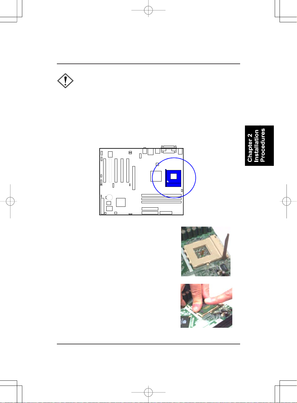
The procedures below shows you how to install your CPU and its fan
and heatsink. First of all, locate the CPU socket on this mainboard.
1. Swing the lever upward to 90 degree.
2. Install the CPU and make sure the the pin 1
orientation by aligning the socket corner marking
with the socket corner closest to the lever tip.
Do not insert the CPU by force. Make sure the
processor is fully inserted into the socket on all
sides.
Apply some thermal materials, such as paste or
tape, on the CPU top; and install a fan with
heatsink that approved by CPU manufacturer
to avoid CPU damage. For detail information,
please refer to the CPU manufacturer website.
CAUTION:
1. The heat sink and fan you installed must be approved by AMD.
2. The mainboard must be placed on a solid place to avoid shaking
|||||while install the heat sink and fan on the board.
3. The heat sink must be contact with the CPU top tightly.
4. Never run the processor without the heat sink properly and firmly
attached. PERMANENT DAMAGE WILL RESULT!

2 - 6
KT-400A/KT-600Dynasty Mainboard Manual
3. Place the fan with heatsink on the CPU top
and press down two plastic clips to hook up
with the holes on the retention module on two
sides.
4. Press down the white bar on each clip to
fasten the fan set on the retention module.
Affix the CPU by pressing the lever downward
and locking it beside the socket.
Connect ATX Power
The 20-hole power plug (top right) is connected
to theATX power 20-pin pinheaders. The 4-hole
12V power plug (bottom right) is inserted in the
ATX_12V power connector.
The plug from the power supply will only insert
in one orientation because of the different hole
sizes. Find the proper orientation and push down
firmly making sure that the pins are aligned.

2 - 7
Installation Procedures
CAUTION:
1.Make sure to unplug the power supply when adding or removing
expansion cards or other system components. Failure to do so
may cause severe damage to both the mainboard and expansion
cards.
2. Always observe static electricity precautions.
3. Please read Handling Precautions at the start of this manual.
4). Install Expansion Cards
This section describes how to connect an expansion card to one of your
system expansion slots.
Expansion cards are printed circuit boards that, when connected to the
mainboard, increase the capabilities of your system.
For example, expansion cards can provide video and sound capabilities. The
mainboard features one AGP and five PCI bus expansion slots.
NOTE: Users The CPU installing procedures should be:
1. Insert the CPU (with its fansink and retention module) on the
|||||||||||||socket.
2. Connect the 4-pin plug of the power supply
3. Connect the 20-pin plug of the power supply.
To remove the processor, please do it in reverse order.

2 - 8
KT-400A/KT-600Dynasty Mainboard Manual
1. Select an available expansion slot.
2. Remove the corresponding slot cover from the computer chassis. Un-
screw the mounting screw that secures the slot cover and pull the slot cover
out from the computer chassis. Keep the slot cover mounting screw nearby.
3. Push the card firmly into the slot.
Push down on one end of the expan-
sion card, then the other. Use this rock-
ing motion until them card is firmly
seated inside the expansion slot. Se-
cure the card with the screw removed
in Step 2.

2 - 9
Installation Procedures
IDE Device Connectors
The two connectors, PRIMARY
and SECONDARY, are used for
your IDE hard disk drives, CD drives,
LS-120|drives, or IDE ZIP drives.
5). Connect Devices
Floppy Diskette Drive Connector
This connector provides the connection with your floppy disk drive.
Insert the floppy ribbon cable
(below) onto the floppy connector.
The colored stripe (indicated by the
arrow head, right) of the ribbon cable
must be the same side with the Pin 1.
Insert the floppy ribbon cable
(below) onto the floppy connector.
The colored stripe (indicated by the
arrow head, right) of the ribbon cable
must be the same side with the Pin 1.

2 - 10
KT-400A/KT-600Dynasty Mainboard Manual
Front Panel Block, Power LED, IR, and Speaker Connector
This block connector includes the connectors for linking with Power LED (3-
pin), HDD LED, power button, power/sleep/message waiting button, reset
buttonon the front panel of the system case. Please identify polarities of plug
wires for the case speaker and LEDs. Please ask vendor about this information
when you buy them and install the system by yourself. The plug wires (next
page) polarities of these buttons will not affect the function.
Fan Connectors
The two connectors, CPU_FAN, SYSTEM_FAN are linked to the CPU fan,
case fan, respectively.
Power Connectors
The 20-pin male block connector is connected to the ATX power supply. The
4-pin male block connector is for theATX_12V power use.All two connectors
are linked with yourATX power supply. The plug from the power supply will
only insert in one orientation because of the different hole sizes. Find the
proper orientation and push down firmly making sure that the pins are aligned.

2 - 11
Installation Procedures
(1) Reset Switch is connected to the reset button. Push this switch to reboot
the system instead of turning the power button off and on.
(2) HDD LED is connected to the IDE device indicator. This LED will blink
when the hard disk drives are activated.
NOTE: Users that want to use IR port must adjust BIOS feature
UART Mode Select to set COM2 at some IR mode upon your IR
device.
(3)Power(Single andDual) /SleepLED
Please refer to the tables below for the representations of LED states.
There is another 3-Pin Power LEDconnector on board for some cases that with
a 3-pin plug.
(4) Power Button is connected with power button. Push this switch allows the
system to be turned on and off rather than using the power supply button.
This manual suits for next models
2
Table of contents
Other FIC Motherboard manuals


