FIC K7M-400A User manual

First International Computer, Inc.
NEW APPROVAL SHEET
RELEASE FROM:FIC R&D
Form update:2002/11/1 QP-R705-F02
FILE NO.
25-11141-00
□
FIC PRODUCT
□
COMPONENT
▓MANUAL □
MECHANICAL
□
P.C.B □
PURCHASE
□
POWER SUPPLY □
SOFTWARE
DATE 2003.11.21
PART NO 25-11141-00
DESCRIPTION
MANU M/B AM39-LS ENG USER' VA0
MODEL AM39-LS
REV.
VENDOR 力捷
REMARK
oApproved by NHRD ▓Approved by FIC-SZ
LINKO □DCC □QA □PMC □CSD
FIC-SZ ▓DCH □R&D ▓VENDOR ▓QA1
□QA2 □IE
NEI-HU □RDCC □VENDOR □FAE □CE
WORLD WIDE □FIC-TX □FIC-BZ □FIC-CZ ▓FIC-GZ
MANAGER
楊博丞 2003.11.21
LEADER
張新政 2003. 11.21
CHECK
謝群根 2003. 11.21
INITIAL
謝群根 2003. 11.21

FIRST
INTERNATIONAL
COMPUTER
COMPONENT
APPROVAL
SHEET
PART NUMBER 25-11141-00 APPLICANT
DESCRIPTION MANU M/B AM39-LS ENG USER' VA0
WHERE USED
BRAND VENDOR 力捷
MODEL(S) AM39-LS MARK P/N
CONTACT 周宇清PHONE (0769) 7313082
COMPONENT OKNG
FUNCTIONAL TEST
RELABLITY TEST
COMPATIBILY TEST
COMMENTS:
CE BY:
CE CHECK: 謝群根
H/W OK NG
ELECTRICAL SPEC
ENVIONMENTAL
COMPATIBILITY FEATURE
COMMENTS:
H/W BY: 謝群根
M/E OK NG
DIMENSION CHECK
MATERIAL CHECK
COATING CHECK
IE CHECK
;
;
COMMENTS:
M/E BY: 謝群根
EMI & SAFETY OK NG
SAF-ETY FEATURE
EMI FEATURE
MATERIAL CHECK
LABELING CHECK
SAFETY BY:
EMI BY: 謝群根
ATTACHMENTS ;SAMPLE DRAWING ;SPEC PHOTO ECN
APPROVAL
;
TEMPORARY
REMARK:
Failure Rateλ(Failure/106hours)= Vendor MIL-HDBK-217F REJECT
1'ST SOURCE 2'ND SOURCE
承 認 書
客 戶
品 名
料 號
客戶確認簽章
工程部 品管部 品管部經理
本公司確認簽章
送樣日期: 月日
______
東莞力捷紙品有限公司
地 址: 東莞市清溪鎮重河管理區河柏橋村
電 話: 0769-7313082088
傳 真: 0769-7313080
E-mail: [email protected]
年_____ _____
才 眾
說 明 書
25-11141-00
曹菊蘭 陳文華 胡培基
2003 11 19

東莞力捷紙品有限公司
產 品 基 本 資 料
確
認
意
見
附樣:
生 產 技 術 資 料 表
產 品
編 號 25-11141-00 品 名 說明書 材 質 封頁: 200P 銅西卡
內頁: 70P 蘭白模造
顏 色 BK+877C 表 面
處 理 OPP 膜(正面) 條碼值:
實測值: 無
尺 寸
規 格 148*210mm 成型方式 裁切, 折頁, 膠裝
核 准 胡 培 基 審 核 曹 菊 蘭 填 表 李 先 芳

K7M-400A
MAINBOARD
MANUAL
DOC No.: M03603
Rev. :A0
Date : 11, 2003
Part No. : 25-11141-00

Handling Precautions
Warning:
1. Static electricity may cause damage to the integrated circuits on
the motherboard. Before handling any motherboard outside of its
protective packaging, ensure that there is no static electric
||||||charge in your body.
2. There is a danger of explosion if the battery is incorrectly
replaced. Replace only with the same or an equivalent type
||||||recommended by the manufacturer.
3. Discard used batteries according to the manufacturer’s
instructions.
4. Never run the processor without the heatsink properly and firmly
attached. PERMANENT DAMAGE WILL RESULT!
Observe the following basic precautions when handling the motherboard
or other computer components:
Wear a static wrist strap which fits around your wrist and is
|||||||||connected to a natural earth ground.
Touch a grounded or anti-static surface or a metal fixture such as a
water pipe.
Avoid contacting the components on add-on cards, motherboards,
and modules with the golden fingers connectors plugged into the
expansion slot. It is best to handle system components by their
mounting brackets.
The above methods prevent static build-up and cause it to be discharged
properly.
Trademark
All trademarks mentioned in this manual are registered properly of
the respective owners.
Handling Precautions
This manual may not, in whole or in part, be photocopied, reproduced,
transcribed, translated, or transmitted in whatever form without the
written consent of the manufacturer, except for copies retained by the
purchaser for personal archival purposes.
Notice

i
Table of Contents
Table of Contents
Chapter 1 Overview
Package Checklist .......................................................................... 1-2
The K7M-400A Mainboard ....................................................... 1-3
Main Features................................................................................ 1-4
FIC Unique Innovation for Users (NOVUS) -
Enhanced Mainboard Features and System Support ..................... 1-6
Chapter 2 Installation Procedures
1). Set System Jumpers .................................................................. 2-2
ClearCMOS ...................................................................... 2-2
BIOS Protect...................................................................... 2-2
Front Side Bus Frequency................................................. 2-3
2). Install Memory Modules .......................................................... 2-4
3). Install the CPU .......................................................................... 2-5
Connect ATX Power.......................................................... 2-6
4). Install Expansion Cards ............................................................. 2-7
5). ConnectDevices ....................................................................... 2-8
Floppy Diskette Drive Connector ...................................... 2-8
IDEDevice Connectors ..................................................... 2-9
Power Connectors ............................................................. 2-9
Front Panel Block, Power LED, IR and Speaker Connector 2-10
1394 Connectors (optional) ............................................... 2-12
CDAudio-In Connector .................................................... 2-12
SPDIF Out Connector ....................................................... 2-13
Serial IRQ Connector......................................................... 2-13
Chassis Intrusion Connector ............................................ 2-14
Fan Connectors ................................................................. 2-14
Serial ATA Connectors ...................................................... 2-15
PS/2 Keyboard and Mouse Connector.............................. 2-16
Printer Connector .............................................................. 2-16
Universal Serial Bus Connectors....................................... 2-17
RJ45 LAN Connector ........................................................ 2-17
Serial Port Connector ........................................................ 2-18
Audio I/O Jacks ................................................................ 2-18
Front Audio Connector ..................................................... 2-19
CRT Connector.................................................................. 2-19

ii
K7M-400AMainboard Manual
Chapter 3 BIOS Setup
CMOS Setup Utility ....................................................................... 3-1
Standard CMOS Setup ................................................................... 3-2
Advanced BIOS Features .............................................................. 3-4
Advanced Chipset Features .......................................................... 3-7
Integrated Peripherals.................................................................... 3-11
Power Management Setup ............................................................. 3-15
PnP/PCI Configurations................................................................. 3-18
PC Health Status ............................................................................ 3-20
Load OptimizedDefaults ................................................................ 3-20
Supervisor/User Password ............................................................ 3-20
Save and Exit Setup........................................................................ 3-21
Exit without Saving ........................................................................ 3-21
1 - 1
Overview
Overview
Chapter 1
The new microATX 462-pin board supports a full range of the latest generation
AMD®Athlon XPprocessors. The leading edge VIA®chipset was de-
signed to work in the 462-pin package running at the FSB 200/266/333/400
MHz. Built using leading edge technology, the AMD®Athlon XPproces-
sors provide a significant improvement in performance over previous proces-
sors. TwoDDR 200/266/333/400 SDRAM sockets allow for up to 2GB memory
capacity. Support for Ultra DMA/133 protocol and its high-speed interface
further ensures that data transfer speeds are improved, especially for the long
sequential transfers required by audio/visual applications.
The board features onboard audio and LAN function; also, the serial ATA
feature replaces the standard parallel ATA physical storage interface and al-
lows future enhancements to the computing platform. It is completely soft-
ware compatible with parallelATA, requiring no modification to your operat-
ing system. For more details, please read the help file in the lst Utilities CD.
The board comes with a versatile range of I/O features such as serial port COM
port,1CRTport,1parallelport,1 LAN,2optional IEEE 1394, 1 PS/2 mouse and
keyboard connector, 8 USB ports, 1 media connector (front audio, Line-in,
Line-out and Mic-in). In addition, the board is equipped with 2 dual channel
enhanced PCI bus master IDE connectors.Ample expansion is available through
3 PCI and 1AGP to allow enjoyment of the AMD CPU’s benefits in internet
applicatons, video/3D graphics performance, and so forth.
Other key features are Remote On/Off, Auto Power Failure Recovery, inte-
grated temperature monitoring and system fan control.Also included are a lst
Utilities CD with enhanced drivers and a few bundled software solutions.
1 - 2
K7M-400AMainboard Manual
NOTE: A 1st Utilities CD, which contains patch files, onboard video/
audio chip drivers, related online help and other useful information,
can be found in your mainboard package.
Please install it immediately after your Windows operating system
installation is complete. Place your 1st Utilities CD in the drive and
an operating menu will appear on your monitor. Please select Auto
Installation. It will automatically detect which software tools (patch
files, drivers) the mainboard needs. Press OK to go through the
whole installation procedure in a very straight forward and easy
way. It will also provide you with a custom installation feature to
select the patch files and software drivers you want for the onboard
chip’s use. The top menu of the 1st Utilities CD lists all the func-
tions that are allowed by this board.
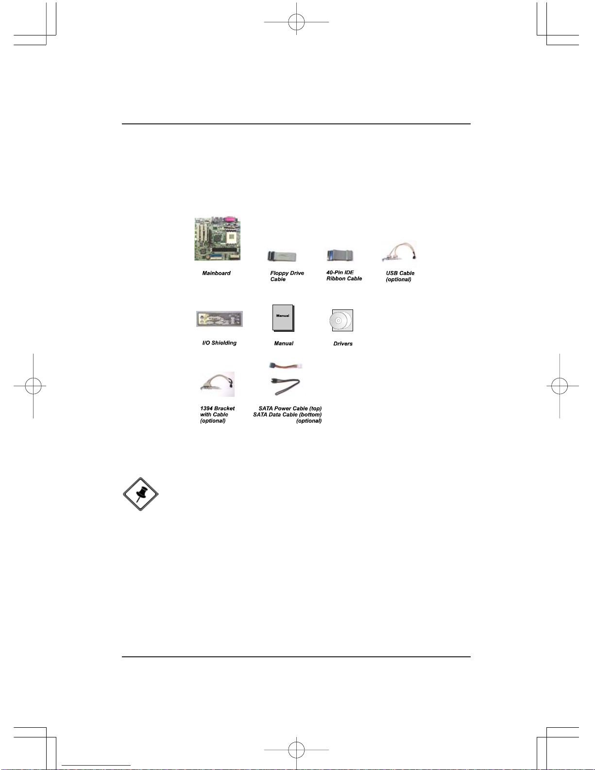
Package Checklist
If you discover any item below was damaged or lost, please contact your
vendor.
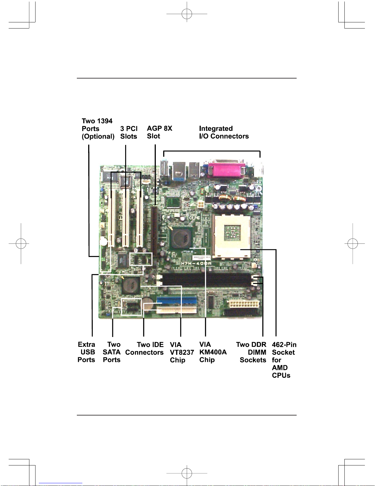
1 - 3
Overview
The K7M-400A Mainboard

1 - 4
K7M-400AMainboard Manual
Main Features
CPU
Duron: 1.0- 1.3GHzatFSB 200MHz
1.6- 1.8GHzatFSB 266MHz
Athlon : 1.0-1.4GHzat FSB200/266 MHz
Athlon XP:
PalominoCore: 1500+ - 2100+ at FSB266MHz
Thoroughbred Core: 1700+- 2600+ atFSB266/333 MHz
Barton Core: 2500+- 3200+ atFSB333/400 MHz
Chipset
North Bridge: VIA®KM400A
South Bridge: VIA®VT8237
Memory
2 Memory Sockets:
Support184-pinDDR200/266/333/400 MHz
total Memory Size up to 2GBs
ExpansionSlots
AGP Slot: Support 2.0 4X/8X (0.8 - 1.5V)
3 PCI Slots
IDEConnections
2 IDE Connectors - PIO Mode, UltraDMA66/100/133
Up to 4Devices
SATAConnections
2 Ports Controlled by embedded VIAVT8237®SATAFunction

1 - 5
Overview
AudioFeatures
AC97 2.2 compliant
LINE_IN,LINE_OUT,MICROPHONE_INJack
Front Audio Pinheaders
I/O Ports
2 IDE Connectors -
PIO, Bus Master, UltraDMA66/100/133
up to 4 Devices
- 1 Serial Port COM1 / 1 CRTPort
2 Serial ATA Connectors
1 Floppy Connector
1 Parallel Port
PS/2 Mouse and PS/2 Keyboard
8 USB 1.1/2.0 Ports
LAN
VT6103L10/100M Fast Ethernet
RTL8110SGiga-bit Ethernet (optional)
MountingHoles
6 Holes
MainboardSize
9.0 x 9.6 (unit: inch)
IEEE 1394 Ports (optional)
VT6307L
2 Ports
1 Bracket with Cable
1 - 6
K7M-400AMainboard Manual
BIOSGuardian
BIOS Guardian effectively acts as a fire-wall against viruses that can at-
tack the BIOS while the system is running and when default is enabled.
WARNING:
BIOSGuardian must be disabled before reflashing the BIOS.
NOTE:
Please read Page 3-7 for detail information.
FIC Unique Innovation for Users (NOVUS) -
Enhanced Mainboard Features and System Support
Easy Key
Instead of completing the multi-layered BIOS setup process, these 3 Easy
Key functions provide direct access to the Sub-Menu when completing
BIOS setting adjustments.
Easy-Keys are as follows:
Ctrl+p: To load Performance Default settings and restart.
Ctrl + f: To load Fail-Safe Default settings and restart.

2 - 1
Installation Procedures
Chapter 2
Installation Procedures
The mainboard has several user-adjustable jumpers on the board that allow you to
configure your system to suit your requirements. This chapter contains information
on the various jumper settings on your mainboard.
To set up your computer, you must complete the following steps:
Step 1 - Set system jumpers
Step 2 - Install memory modules
Step 3 - Install the Central Processing Unit (CPU)
Step 4 - Install expansion cards
Step 5 - Connect ribbon cables, cabinet wires, and power supply
Step 6 - Set up BIOS software
Step 7 - Install supporting software tools
WARNING: Excessive torque may damage the mainboard. When
using an electric screwdriver on the mainboard, make sure that
the torque is set to the allowable range of 5.0 ~ 8.0kg/cm.
Mainboard components contain very delicate Integrated Circuit
(IC) chips. To prevent static electricity from harming any of the
sensitive components, you should follow the following precau-
tions whenever working on the computer:
1. Unplug the computer when working on the inside.
2. Hold components by the edges and try not to touch the IC
||||chips, leads, or circuitry.
3. Wear an anti-static wrist strap which fits around the wrist.
4. Place components on a grounded anti-static pad or on the bag
that came with the component whenever the components are
separated from the system.
2 - 2
K7M-400AMainboard Manual
1). Set System Jumpers
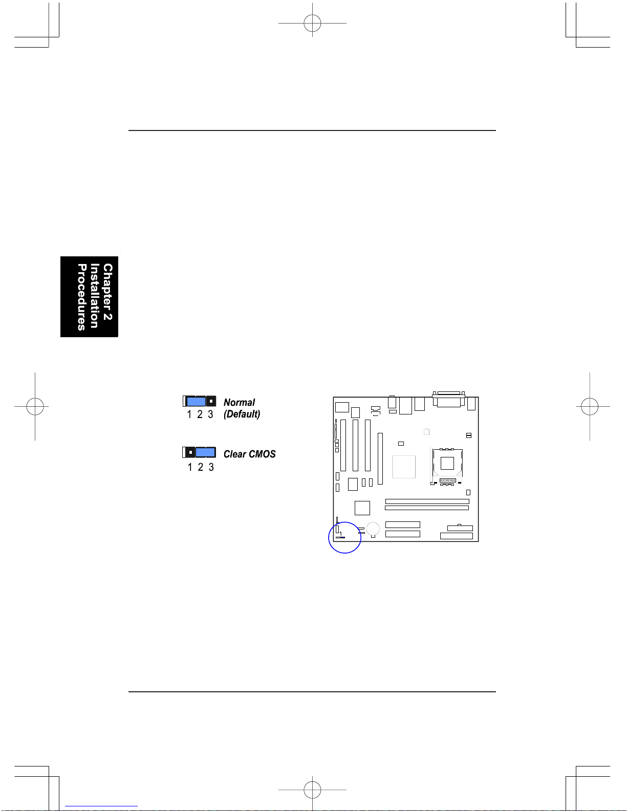
BIOS Protect
The jumper helps to prevent the BIOS ROM from being overwritten by
mistake.
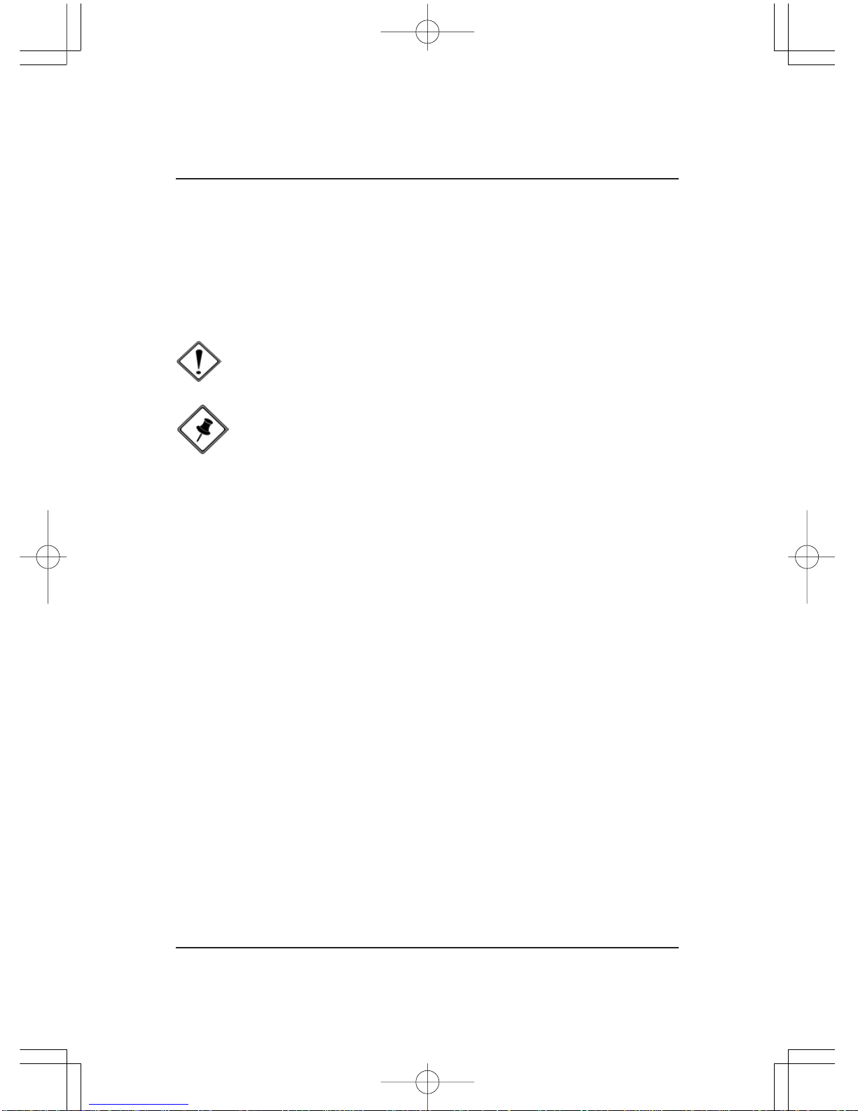
Clear CMOS
The CMOS RAM is powered by the onboard button cell battery.
To clear the RTC data:
(1) Turn off your computer;
(2) Open the system case and disconnect the ATX power cable;
(3) Place the jumper cap onto the pinpair 2-3 for at least 6 seconds
to clear CMOS data;
(4) Place the jumper cap onto the pinpair 1-2 to normal operation;
(5) Close the system case and connect the ATX power cable;
(6) Turn on your computer until CMOS checksum error appears;
(7) Press the Delete key as it boots;
(8) Enter the BIOS Setup to re-enter user preferences.
2 - 3
Installation Procedures
Front Side Bus Frequency
The jumpers together decide the setting of FSB frequency of the mainboard.

2 - 4
K7M-400AMainboard Manual
Press the clips outward with both hands to remove the DIMM.
3. The clip on both ends of the
socket will close up to hold the
DDRDIMM in place when theDDR
DIMM reaches the socket bottom.
2. InstallDDRDIMM straight
down into the socket 1 using both
hands, then socket 2, and so forth.
1. LocateDDRDIMM sockets
on the mainboard.
2). Install Memory Modules

2 - 5
Installation Procedures
1. Swing the lever upward to 90 degree.
2. Install the CPU, making sure of the pin 1
orientation by aligning the socket corner marking
with the socket corner closest to the lever tip.
Do not insert the CPU by force. Make sure the
processor is fully inserted into the socket on all
sides.
3). Install the CPU
The mainboard has a built-in Switching Voltage Regulator to support CPU
Vcore autodetection. That is, it has the ability to detect and recognize the CPU
voltage, clock, ratio. Users can view the report about CPU frequency through
Frequency / Voltage Control on the BIOS Setup Screen.
The procedures below shows you how to install your CPU and its fan
and heatsink. First of all, locate the CPU socket on the mainboard.
CAUTION:
1. The heat sink and fan you installed must be approved by AMD.
2. The mainboard must be placed on a solid surface to avoid shak
ing while install the heat sink and fan are installed on the board.
3. The heat sink must make tight contact with the CPU top.
4. Never run the processor without the heat sink properly and firmly
attached. PERMANENTDAMAGE WILL RESULT!
Apply some thermal materials, such as paste or
tape, on the CPU top; and install a fan with a
heatsink is approved by the manufacturer to
avoid CPU damage. For detail information,
please refer to the CPU manufacturer website.
Affix the CPU by pressing the lever downward
and locking it beside the socket.
2 - 6
K7M-400AMainboard Manual
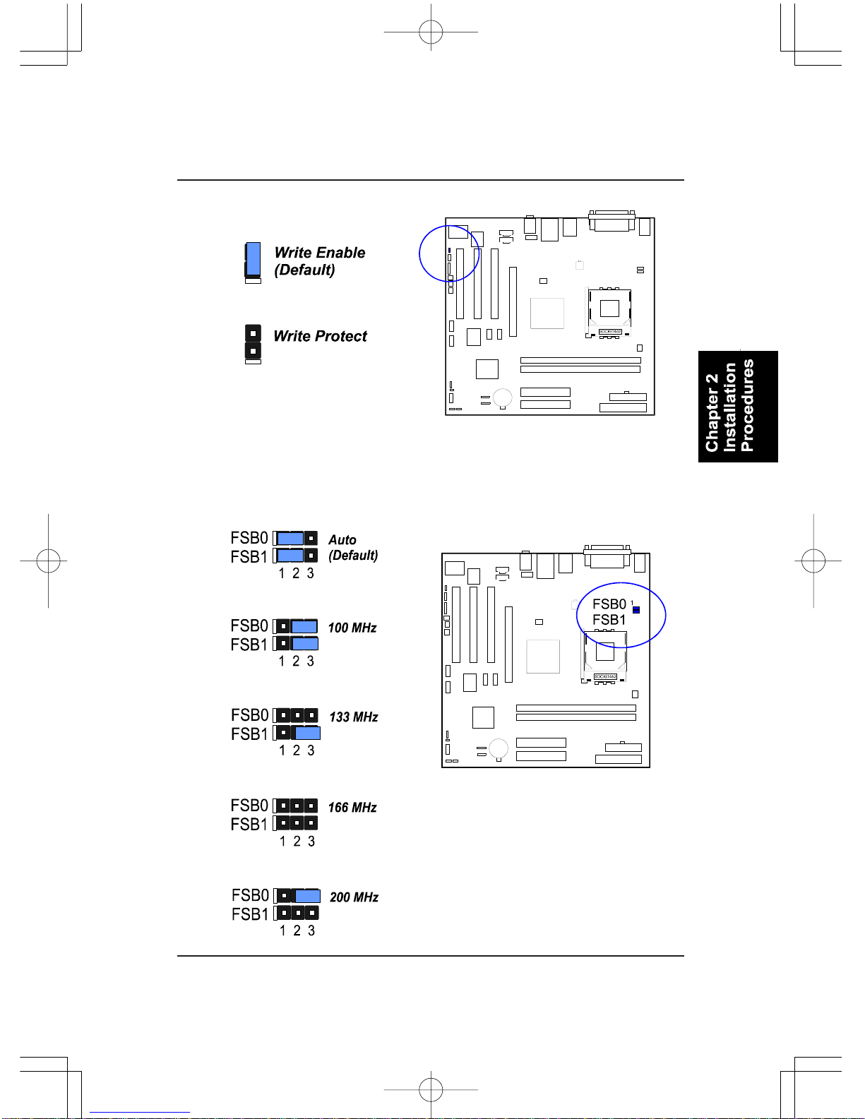
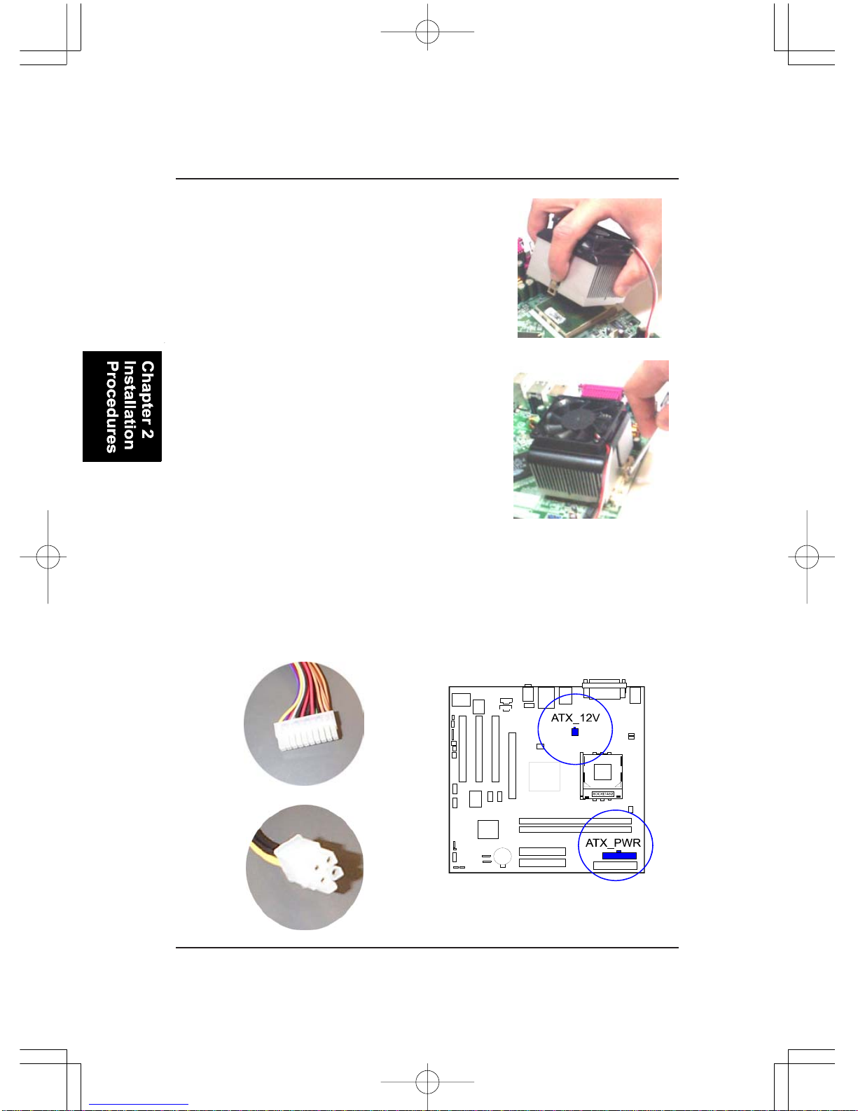
Connect ATX Power
The 20-hole power plug (1st figure) is connected to the ATX power 20-pin
pinheaders. The 4-hole 12Vpower plug (2nd figure) is inserted in theATX_12V
power connector.
3. Place the fan with heatsink on the CPU top
and press down on the two plastic clips,
hooking them up with the holes on the two
sides of the retention module.
4. Press the white bar on each clip down to
fasten the fan set on the retention module.
Table of contents
Other FIC Motherboard manuals


