FIC AN19E User manual

AN19E/AN19C
MAINBOARD
MANUAL
DOC No.: M02811
Rev. : A0
Date : 9, 2002
Part No. : 25-11659-00

Handling Precautions
Warning:
1. Static electricity may cause damage to the integrated circuits on
the motherboard. Before handling any motherboard outside of its
protective packaging, ensure that there is no static electric charge
in your body.
2. There is a danger of explosion if the battery is incorrectly
replaced. Replace only with the same or an equivalent type
recommended by the manufacturer.
3. Discard used batteries according to the manufacturer’s
instructions.
4. Never run the processor without the heatsink properly and firmly
attached. PERMANENT DAMAGE WILL RESULT!
Observe the following basic precautions when handling the motherboard
or other computer components:
nWear a static wrist strap which fits around your wrist and is
connected to a natural earth ground.
nTouch a grounded or anti-static surface or a metal fixture such as a
water pipe.
nAvoid contacting the components on add-on cards, motherboards,
and modules with the golden fingers connectors plugged into the
expansion slot. It is best to handle system components by their
mounting brackets.
The above methods prevent static build-up and cause it to be discharged
properly.
Trademark
All trademarks mentioned in this manual are registered properly of
the respective owners.
Handling Precautions
This manual may not, in whole or in part, be photocopied, reproduced,
transcribed, translated, or transmitted in whatever form without the
written consent of the manufacturer, except for copies retained by the
purchaser for personal archival purposes.
Notice

1 - 1
Overview
Overview
Chapter 1
The new 1stMainboard®AN19E/AN19CÔis an ATX sized motherboard sup-
porting the latest generation of AMD®processors at industry leading speeds.
By utilizing DDR ( Double Data Rate ) transfer rate the 100/133 MHz system bus
effectively reaches Front Side Bus speeds of 200/266/333 MHz. The board
provides users with an ATA133 data transaction for hard drives and has 3
PC1600/PC2100/PC2700 DDR333 DIMMs for up to 3 GB.
The optional serial ATA feature replaces the standard parallel ATA physical
storage interface and allows future enhancements to the computing platform.
It completely software compatible with parallel ATA, requiring no mofication
to your operating system.The board is equipped with 2 dual channeled en-
hanced PCI bus master IDE connectors, plus two optional IDE RAID ATA133
connectors for supporting more efficient data backup.
The board is based around the high performance VIA KT400Ôas North Bridge
and the VIA VT8235Ô as South Bridge. Its AGP 8X functions supported AGP
3.0 interface and the most robust 3D games with software environments. The
AGP slot allows 1.5 volt AGP card only and Maximum AGP interface bandwith
2.1 GB/s.

1 - 2
AN19E/AN19CMainboardManual
IMPORTANT:AMDCPUHEATSINKINSTALLATION
Be ware finish heat sink install. Before you boot system, please
check the heat sink is complete contact with die of CPU.
The poor contact will bring about over heat, it may damage your
processor.
Itis strongly recommendedthatat least a250-wattATX powerpupply
be used for this motherboard. Make sure that your ATX power sup-
ply can supply at least 20 amperes on teh +5-Volt lead and 10mA
on the +5-Volt standby lead (+5VSB). Your system may become
unstable / unreliable and may experience difficulty in powering up if
your power supply is inadequate.
Package Checklist
If you discover any item below was damaged or lost, please contact your
vendor.
þThe mainboard þThis user manual
þFDDcable þ Drivers CD þATA-66/100 cable
oRAIDATA-100 cable(optional)
oUSB cable (optional) oI/O shield (optional)
oGameport cable(optional) oSPD650 cable (optional)
oSerialATA cable(optional) oBluetooth module(optional)
1 - 3
Overview
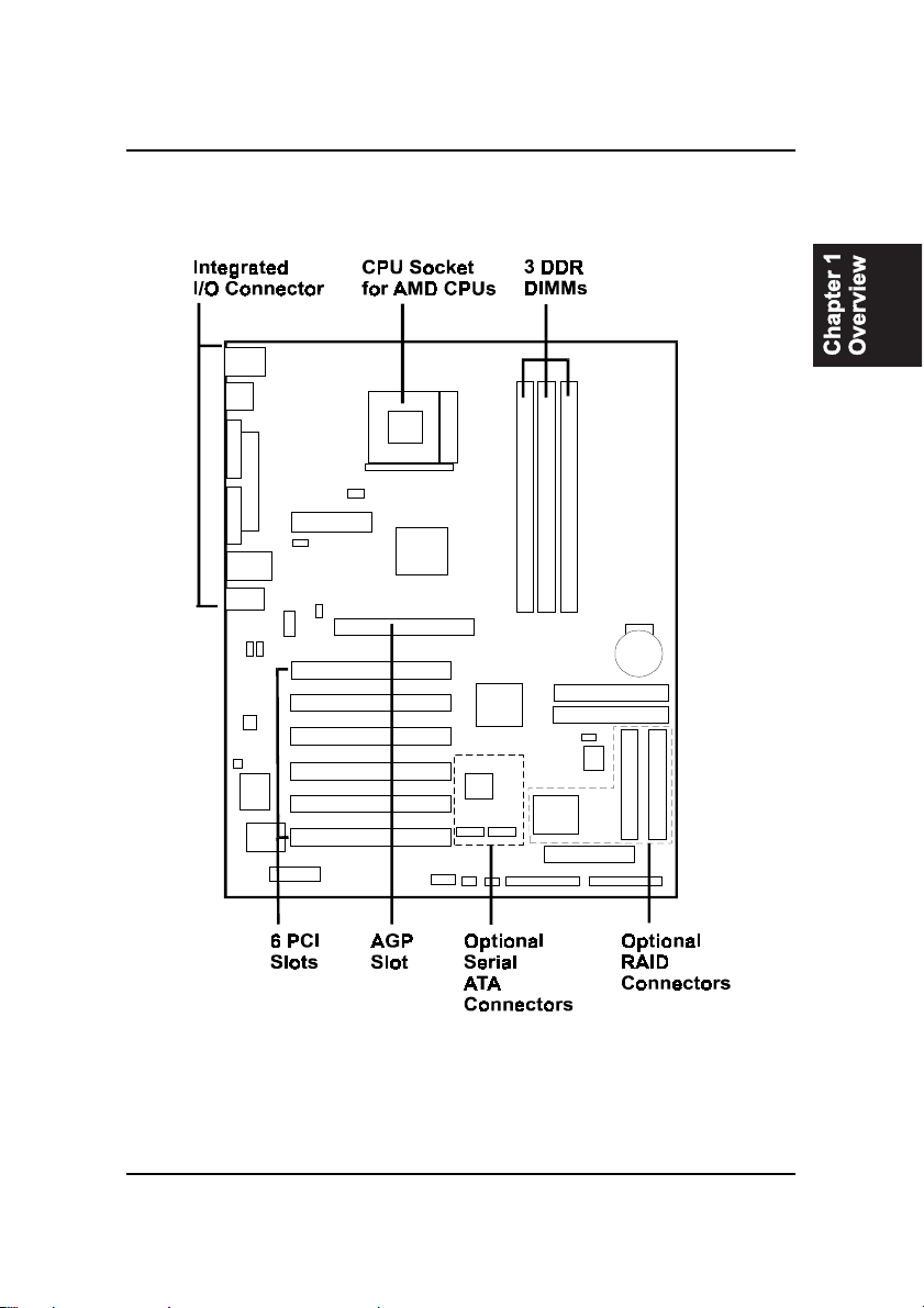
The AN19E/AN19C Mainboard

1 - 4
AN19E/AN19CMainboardManual
Main Features
nEasy Installation
||BIOS with support for Plug and Play, auto detection of IDE hard drives,
||LS-120|drives, IDE ZIP drives, Windows 98SE, Windows ME, Windows
||NT, Windows 2000, Windows XP, and OS/2.
nLeading Edge Chipset
VIA KT400 is a single-chip North Bridge for AMD CPUs with 200/266/333
MHz Front Side Bus with AGP 8X and PCI plus advanced memory con-
troller that supports PC1600/PC2100/PC2700 DDR SDRAM. VIA VT8235
is a Vlink client highly integrated controller that supports PC99-compliant
system. The VT8235 supports ATA133 protocol.
nVersatile Main Memory Support
Accepts up to 3 GB DRAM using three DDR333 DIMMs from 256 MB to 3
GB with support for lightenning-fast (PC1600/PC2100/PC2700) DDR
SDRAM .
nEnhanced PCI Bus Master IDE Controller with UltraDMA/33/66/100/
133 Support
Integrated Enhanced PCI Bus Master IDE controller features two dual-
channel connectors that up to four Enhanced IDE devices, including CD-
ROM and Tape Backup Drives, as well as Hard Disk Drives supporting
the new UltraDMA/133 Mode 6 protocol, standard PIO Mode 3, PIO
Mode 4, DMA Mode 2, DMA Mode 4, UltraDMA/100 Mode 5 devices
are also supported.
nAMD Processors Support
The socket A compatible AMD AthlonÔXP processor 1500+ to 2000+,
600MHz to 1.4GHz AMD AthlonÔand AMD DuronÔprocessor up to
1.3GHz.
nOptional IDE RAID Level 0/1 Support
The optional Promise IDE RAID controller and two connectors offer
ATA100 and Level 0, 1 for backing up huge amount data in a more effi-
cient way.

1 - 5
Overview
nAGP and PCI Expansion Slots
One AGP Bus and six PCI Bus expansion slots provided the room to
install a full range of add-on cards.
nCompact Onboard Audio Subsystem
Built-in AC97 digital audio by Realtek ALC650 (5.1 channel) that com-
plaint with AC97 2.2 specification. It provides 5.1-channel which is slot
selectable DAC (Digital Analog Converter) output for multi-channel ap-
plications. It also supports digital SPDIF functions.
nSuper Multi Input/Output (I/O) Support
Integrated Plug and Play multi-I/O chipset features two high-speed UART
16550 compatible serial ports, one EPP/ECP capable parallel port, one
game port, and one FDD connector.
nOnboard Accelerated Graphics Port (AGP)
The motherboard is installed one 32-bit 1.5V AGP 8X bus with a dedi-
cated 66MHz/133MHz path from the graphics card to the system memory
offering much greater bandwidth than the 32-bit PCI bus does. AGP en-
abled 3D graphics cards can directly access main memory across this fast
path instead of using local memory.
nConvenient Rear Panel USB Connection Support
Four USB 2.0 ports integrated in the rear I/O panel and two extra USB 2.0
ports for either front or rear panel connection allow convenient and high-
speed Plug and Play connections to the growing number of USB 2.0
compliant peripheral devices on the market.
nLAN Support (optional)
Onboard optional LAN controller with one optional jack integrated with
other rear panel I/O connectors provides users with a convenient con-
nection with network environment. The integrated 10/100MB fast Ethernet
controller in chipset with external VIA VT6103Ôphysical Layer by RJ-45
connector.

1 - 6
AN19E/AN19CMainboardManual
nIDE RAID Support (optional)
The optional feature allows this board to back up huge amount data in an
economic way. The chip on this board is a PCI-to-IDE UDMA/ATA133
RAID controller and designed for mainboard use. It offers features that of
level 0, 1, 0+1 and supports the most popular operating systems, such as
Windows 95/98/ME/NT 4.0/2000/XP and Linux.
nSerial ATA Support (optional)
The optional feature offers up to Serial ATA device for replacing the
parallel ATA interface and providing greater throughput. It supports cur-
rent operating systems, software, and all ATA and ATAPI devices includ-
ing high capacity removable devices, optical devices, tape storage de-
vices, and zip drives.

2-1
Installation
The mainboard has several user-adjustable jumpers on the board that allow
you to configure your system to suit your requirements. This chapter
contains information on the various jumper settings on your mainboard.
To set up your computer, you must complete the following steps:
?
?nStep 1 -Set system jumpers
?nStep 2 - Install memory modules
?nStep 3 - Install the Central Processing Unit (CPU)
?nStep 4 - Install expansion cards
?nStep 5 - Connect ribbon cables, cabinet wires, and power
?supply
?nStep 6 - Set up BIOS software
?nStep 7 - Install supporting software tools
WARNING: Excessive torque may damage the
mainboard. When using an electric screwdriver on the
mainboard, make sure that the torque is set to the
allowable range of 5.0 ~ 8.0kg/cm.
Mainboard components contain very delicate Integrated
Circuit (IC) chips. To prevent static electricity from
harming any of the sensitive components, you should
follow the following precautions whenever working on the
computer:
1. Unplug the computer when working on the inside.
2. Hold components by the edges and try not to touch the
IC chips, leads, or circuitry.
3. Wear an anti-static wrist strap which fits around the
wrist.
4.Place components on a grounded anti-static pad or on
the bag that came with the component whenever the
components are separated from the system.
Chapter 2

AN19E/AN19C Mainboard Manual
2-2
Mainboard Layout

Installation
2-3
Easy Installation Procedure
The following must be completed before powering on your new
system:
CPU Installation
Jumper Settings
System Memory Configuration
Device Connectors
External Modem Ring-in Power ON and Keyboard Power ON
Functions (KBPO)
STR Function
CPU Overheating Protection
CPU Installation
CPU Insertion: (use AMD AthlonTM as reference)
Step 1
Open the socket by raising the actuation lever.
Step 2
Insert the processor.
Ensure proper pin 1 orientation by aligning the FC-PGA corner
marking with the socket corner closest to the actuation arm tip. The
pin field is keyed to prevent mis-oriented insertion. Do not force
processor into socket. If it does not go in easily, check for mis-
orientation and debris.
Make sure the processor is fully inserted into the socket on all sides.

AN19E/AN19C Mainboard Manual
2-4
Step 3
Close the socket by lowering and locking the actuation
lever.
Thermal compound and qualified heatsink recommended by AMD
are a must to avoid CPU overheat damage. For more information
about installing your CPU, please refer to the AMD website article
socket A AMD processor and Heatsink Installation Guide”
http://www.amd.com/products/cpg/athlon/pdf/23986.pdf.
Jumper Settings
JBAT
CMOS Clear
1-2: Normal (Default)
2-3: Clear CMOS
JCK1
CPU Host Clock Select
1-2: BIOS Setting (Default)
2-3: 133MHz

Installation
2-5
System Memory Configuration
Memory Layout
The mainboard accommodates three PC1600/2100/2700 184-pin
DIMMs (Dual In-line Memory Modules):
•Supports up to 3.0GB of 200/266/333MHz DDR SDRAM
•Supports up to 1GB per DIMM with maximum memory size
up to 3GB (refer to Table 1)
•Supports DDR 200/266/333 unregistered 184-pin non-ECC
DDR SDRAM DIMMs
•Supports configurations defined in the JEDEC DDR DIMM
specification
NOTE: Use DDR SDRAM (Double-Data-Rate Synchronous
DRAM) modules only.
The figure and table below show several possible memory
configurations.
DDR DIMM 1
DDR DIMM 3
DDR DIMM 2 Bank 0/1
Bank 4/5
DDR
Synchronous
DRAM
Bank 2/3
Total Memory DDR DIMM 1
(Bank 0/1) DDR DIMM 2
(Bank 2/3) DDR DIMM 3
(Bank 4/5)
= 1GB
Maximum
DDR SDRAM*
64MB, 128MB, 256MB,
512MB, 1GB* X 1 None None
= 2GB
Maximum
DDR SDRAM*
64MB, 128MB, 256MB,
512MB, 1GB* X 1
DDR SDRAM*
64MB, 128MB, 256MB,
512MB, 1GB* X 1 None
= 3GB
Maximum
DDR SDRAM*
64MB, 128MB, 256MB,
512MB, 1GB* X 1
DDR SDRAM*
64MB, 128MB, 256MB,
512MB, 1GB* X 1
DDR SDRAM*
64MB, 128MB, 256MB,
512MB, 1GB* X 1

AN19E/AN19C Mainboard Manual
2-6
*DDR SDRAM supports 64, 128, 256, 512MB and 1GB DIMM
modules using 512Mb technology.
NOTES:
•DO NOT MIX the unbuffered and registered DDR SDRAM
on DIMM1, DIMM2 and DIMM 3 socket.
•Using non-compliant memory with higher bus speeds
(overclocking) may severely compromise the integrity of the
system.
DIMM Module Installation
DIMMs have 184 pins and one notch thatmatches with the DDR
DIMM socket. DIMM modules are installed by placing the chip
firmly into the socket and pressing straight down until the white
clips close and the module fits tightly into the DIMM socket.
To remove the DIMM module press down the white clips
and the module is released from the socket.
FAN1 / FAN2 / FAN3:
CPU/Chassis/Power Fan Power Connectors
FAN1:
CPU Fan
GND
+12V
Rotation
FAN2:
Chassis Fan
GND
+12V
Rotation

Installation
2-7
FAN3:
PW Fan
GND
+12V
NC
WOL1:WOL (Wake On LAN) Connector
Reserved for an NIC (Network Interface Card) to wake the system
from power saving mode.
GND
PME
+5V Standby
IDE1/2: Ultra DMA-66/100/133 Primary/Secondary IDE
Connector (Blue)
IDE3/4: Ultra DMA-66/100/133 & RAID Primary/Secondary IDE
Connector (Red) (Optional)
Supported by the HPT372 chipset
FDD1: Floppy Controller Connector (Black)
PW1: ATX Power Connector
(20-pin power connector)
GAME1: Game Port Connector

AN19E/AN19C Mainboard Manual
2-8
CD1: CD Audio_IN Connector
CD_IN_Left
1
CD_IN_Right
CD_Reference
AUX1:Auxiliary Line_IN Connector
AUX_IN_Left1
AUX_IN_Right
GND
AUD2: Front Panel Audio Connector
When headphones are plugged into the front panel headphone jack,
the rear panel audio output connectors are disabled.
If the front panel interface board is not connected to the front panel
audio header, short pins 5 - 6 and 9 -10 on the front panel audio
header.
If these pins are not shorted, the rear panel audio connectors
are inoperative.
Settings
Pins (5-6) & (9-10) Short (default): Only the Onboard Rear
Audio Speaker can be used.
Pins (5-6) & (9-10) Open: Only Front Panel Audio Speaker can
be used.

Installation
2-9
SPDIF1: Sony/Philips Digital InterFace
This connector is the digital link between the mainboard and
your audio devices, such as CD player, sampler or DAT recorder.
It allows the digital transmission of audio data in SPDIF format.
1
5
2
6
VCC
NC
GND
SPDIF_IN
SPDIF_OUT
SATA1 / SATA2: (Optional )
1.5Gbps serial ATA Connectors
SATA1 and SATA2 enable you to connect two serial ATA devices
that conform to the Serial ATA specification.
Serial ATA supports all ATA and ATAPI devices, including high
capacity removable devices, optical devices, tape storage
devices, and zip devices.
USB3:USB port header for two USB2.0 ports. The USB3 is
used to connect bluetooth module for wireless connection.
1
VCC
VCC
GND
GND
-Data
-Data
+Data
+Data
5
6
10

AN19E/AN19C Mainboard Manual
2-10
USB port header pin descriptions.
PIN# Wire color Signal Name Comment
1Red Vcc Cable Power
2White -Data Data
3Green +Data Data
4Black Ground Cable Ground
5Black Ground Case Ground
6Black Ground Case Ground
7Black Ground Cable Ground
8Green +Data Data
9White -Data Data
10 Red Vcc Cable Power
LED1: 80 Port Debug LED (Optional)
80 Port Debug 7-segment LED display.
CAUTION !
Please make sure the USB cable has the same pin
assignment. The different pin assignment may be caused
damage of system.

Installation
2-11
wPower On/Off
This is connected to the power button on the case. Using the
Soft-Off by Pwr-BTTN feature, you can choose either Instant Off
(turns system off immediately), or 4 sec delay (push the button for
4 seconds before the system turns off). When the system is in 4
sec delay mode, suspend mode is enabled by pushing the button
momentarily.
wTurbo LED indicator
wIDE LED indicator
LED on when onboard PCI IDE Hard disks are being accessed.
wIR Connector
1. VCC 4. GND
2. CIRRX 5. IRTX
3. IRRX
wPower LED
Power LED connector
1. Power LED(+) 4. NC
2. N/C 5. GND
3. GND

AN19E/AN19C Mainboard Manual
2-12
External Modem Ring Power ON and
Keyboard Power ON Functions (KBPO)
Modem Ring Power ON Function
The I/O chipset provides the two serial ports with the External
Modem Ring-in Power ON function. Once you connect an external
modem to COM1 or COM2, the mainboard enables you to turn on
the system through remote and host dial-up control.
Keyboard Power ON Function
The mainboard features a keyboard power on function that enables
you to turn on the power supply using a keypress. Follow these
instructions to enable the Keyboard Power ON function .
Step : Use the Keyboard Power ON function (KBPO) to turn on the
system by using password, or hot key combination as set in the
BIOS IRQ/Event Activity Detect submenu of Power Management
Setup menu. The BIOS default setting is keyboard <Ctrl> + <F1>.
To power off the system, use the soft-OFF function under Windows
2000/98/95 (refer to Windows online help).
NOTES:
•Intel ATX version 2.0 specification recommends you use a
power supply that supplies >=1.0 A in 5 VSB. However, this
mainboard supports a 5 VSB standby power supply > = 0.1A
(100mA).
We recommend you use the power supply with 1.0 A in 5
VSB, which supports PCI 2.2 specification for remote power-
on and wake-up functions.
Other manuals for AN19E
1
This manual suits for next models
1
Table of contents
Other FIC Motherboard manuals


