FIC PA-2007 User manual

1
Installation Procedures
The PA-2007 has several user-adjustable jumpers on the board that allow you to
configure your system to suit your requirements. This chapter contains
information on the various jumper settings on your mainboard.
To set up your computer, you should follow these installation steps:
nStep 1 -
Set system jumpers Read this chapter for jumper settings.
nStep 2 -
Install RAM modules. Please consult Install RAM modules of the
English manual.
nStep 3 -
Install the CPU. Read this chapter for jumper settings.
nStep 4 -
Install expansion cards. Please consult Install expansion cards of
the English manual.
nStep 5 -
Connect cables and power supply. Please consult Connect cables
and power supply of the English manual.
nStep 6 -
Set up BIOS features. Please read Chapter Two of this manual.
CAUTION : If you use an electric drill to install this mainboard on your
chassis, please wear a static wrist strap. The recommended torque is from
5.0 to 8.0 kg/cm to avoid damaging the chips’ pins.
Chapter 1

PA-2007 Mainboard Manual
2
Setting the System Jumpers
Jumpers
Jumpers are used to select the operation modes for your system. Some jumpers
on the board have three metal pins with each pin representing a different
function. To set a jumper, a black cap containing metal contacts is placed over
the jumper pins according to the required configuration. A jumper is said to be
shorted when the black cap has been placed on one or two of its pins. The types
of jumpers used in this manual are shown below:
NOTE : Users are not encouraged to change the jumper settings not listed in
this manual. Changing the jumper settings improperly may adversely affect
system performance.
Clear Password: CPW
This jumper allows you to set the password configuration to Enabled or
Disabled. You may need to enable this jumper if you forget your password.
Installation Procedures
3
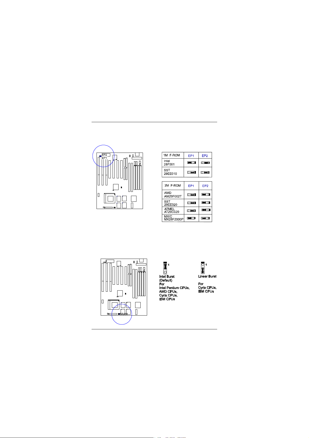
Flash ROM Type Selection: EP1, EP2
These two jumpers allow you to select the flash ROM type (1MB).
CPU to SRAM Data Transacting Mode Selection: SRAM
This jumper allows you to select the CPU-to-SRAM data read/write mode.
If you install a Cyrix or IBM processor on this mainboard, please set at 2-3 pin
pair and set the Linear Burst feature of Chipset Features Setup, Chapter 2.
PA-2007 Mainboard Manual
4
Installing the CPU
The CPU module resides in the Zero Insertion Force (ZIF) socket on the
mainboard. Follow the tables below to set the jumpers for your processor. For
specific jumpers settings for Intel Pentium® MMX, Pentium®, AMD-K5/K6
and Cyrix/IBM 6x86MX™/6x86™ processors, please consult the English
manual.
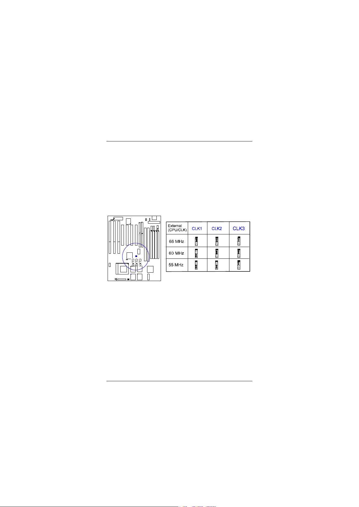
CPU External Clock (BUS) Frequency: CLK1, CLK2, CLK3
The table below shows the jumper settings for the different CPU speed
configurations.

Installation Procedures
5
CPU to Bus Frequency Ratio: FREQ1, FREQ2, FREQ3
These three jumpers are used in combination to decide the ratio of the internal
frequency of the CPU to the bus clock.

PA-2007 Mainboard Manual
6
This Page Intentionally Left Blank

7
Award BIOS Setup
The mainboard comes with the Award BIOS chip that contains the ROM Setup
information of your system. This chip serves as an interface between the
processor and the rest of the mainboard's components. This chapter explains the
information contained in the Setup program and tells you how to modify the
settings according to your system configuration.
CMOS Setup Utility
A Setup program, built into the system BIOS, is stored in the CMOS RAM that
allows the configuration settings to be changed. This program is executed when
the user changes system configuration; the user changes system backup battery;
or the system detects a configuration error and asks the user to run the Setup
program. At power-on RAM testing, the message Press DEL to enter Setup
appears. Use the arrow keys to select and press Enter to run the selected
program.
Chapter 2

PA-2007 Mainboard Manual
8
Standard CMOS Setup
The Standard CMOS Setup screen is displayed above. System BIOS
automatically detects memory size, thus no changes are necessary. It has a few
items for setting. Each item may have one or more option settings. It allows you
to change the system Date and Time, IDE hard disk, floppy disk drive types for
drive A: and B:, boot up video display mode, and POST error handling
selection. Use the arrow keys to highlight the item and then use the PgUp, or
PgDn keys to select the value you want in each item.
Hard Disk Configurations
TYPE:
Select from 1 to 45 to fill remaining fields with predefined values of disk
drives. Select User to fill the remaining fields. Select Auto to detect the
HDD type automatically.
SIZE:
The hard disk size. The unit is Mega Bytes.
CYLS:
The cylinder number of the hard disk.

Award BIOS Setup
9
HEAD:
The read/write head number of hard disk.
PRECOMP:
The cylinder number at which the disk drive changes the write timing.
LANDZ:
The cylinder number that the disk drive heads (read/write) are seated
when the disk drive is parked.
SECTOR:
The sector number of each track defined on the hard disk.
MODE:
Select Auto to detect the mode type automatically. If your hard disk supports
the LBA mode, select LBA or Large. However, if your hard disk cylinder is
more than 1024 and does not support the LBA function, you have to set at
Large. Select Normal if your hard disk supporting cylinders is below 1024.
Please read page 60 of this manaul for more information.
Software Turbo Speed
The BIOS supports Software Turbo Speed feature. Instead of pressing the
Turbo Speed Button on the front panel, simply press the Alt, Ctrl, and +
keys at the same time to enable the Turbo Speed feature; and press the Alt,
Ctrl, and - keys at the same time to disable the feature.

PA-2007 Mainboard Manual
10
BIOS Features Setup
Moving around the BIOS and Chipset Features (refer to the next section) Setup
programs shown above works the same way as moving around the Standard
CMOS Setup program. Users are not encouraged to run the BIOS and Chipset
Features Setup programs. Your system should have been fine-tuned before
shipping. Improper Setup may cause the system to fail, consult your dealer
before making any changes.
Virus Warning
When enabled, assigns the BIOS to monitor the master boot sector and the
DOS boot sector of the first hard disk drive.
The options are: Enabled, Disabled (Default).
CPU Internal Cache
When enbled, improves the system performance. Disable this item when
testing or trouble-shooting.
The options are: Enabled (Default), Disabled.
External Cache
When enabled, supports an optional cache SRAM.
The options are: Enabled (Default), Disabled.
Quick Power On Self Test
When enabled, allows the BIOS to bypass the extensive memory test.
The options are: Enabled, Disabled (Default).

Award BIOS Setup
11
Boot Sequence
Allows the system BIOS to first try to boot the operating system from the
selected disk drive.
The options are: A, C (Default); C, A; C, CDROM, A; CDROM, C, A.
Swap Floppy Drive
When enabled, allows you to switch the order in which the operating system
accesses the floppy drives during boot up.
The options are: Enabled, Disabled (Default).
Boot Up Floppy Seek
When enabled, assigns the BIOS to perform floppy diskette drive tests by
issuing the time-consuming seek commands.
The options are: Enabled (Default), Disabled.
Boot Up Numlock Status
When set to On, allows the BIOS to automatically enable the Num Lock
Function when the system boots up.
The options are: On (Default), Off.
Port 92H Fast A20G
When enabled, allows the A20G bus line signal generated from the chipset
VT82C586A PC/AT to directly pass to port 92H, instead of the keyboard
controller. It will speed up the system performance.
The options are: Fast (Default), Normal.
Typematic Rate Setting
The term typematic means that when a keyboard key is held down, the
character is repeatedly entered until the key is released. When this item is
enabled, you may change the typematic repeat rate.
The options are: Disabled (Default), Enabled.
Typematic Rate (Chars/Sec)
Sets the rate of a character repeat when the key is held down.
The options are: 6 (Default), 8, 10, 12, 15, 20, 24, 30.
Typematic Delay (Msec)
Sets the delay time before a character is repeated.
The options are: 250 (Default), 500, 750, 1000 millisecond.

PA-2007 Mainboard Manual
12
Security Option
Allows you to set the security level of the system.
The options are: Setup (Default), System.
PCI/VGA Palette Snoop
When enabled, allows you install an enhanced graphics adapter card. If your
graphics adapter card does not support the Pallete Snoop function, please set
at Disable to avoid system malfunctions.
The options are: Enabled, Disabled (Default).
OS Select For DRAM > 64MB
If your operating system (OS) is OS2, select the option OS2; otherwise, stay
with the default setting Non-OS2.
The options are: Non-OS2 (Default), OS2.
Video BIOS Shadow
When enabled, allows the BIOS to copy the video ROM code of the add-on
video card to the system memory for faster access.
The options are: Enabled (Default), Disabled.
C8000-CBFFF to DC000-DFFFF Shadow
When enabled, allows the BIOS to copy the BIOS ROM code of the add-on
card to system memory for faster access. It may improve the performance of
the add-on card. Some add-on cards will not function properly if its BIOS
ROM code is shadowed. To use these options correctly, you need to know
the memory address range used by the BIOS ROM of each add-on card.
The options are: Enabled, Disabled (Default).

Award BIOS Setup
13
Chipset Features Setup
Video BIOS Cacheable
When enabled, allows the system to use the video BIOS codes from SRAMs,
instead of the slower DRAMs or ROMs.
The options are: Enabled (Default), Disabled.
System BIOS Cacheable
When enabled, allows the ROM area F000H-FFFFH to be cacheable when
cache controller is activated. The recommended setting is Disabled
especially for high speed CPUs (200 MHz and above).
Memory Hole At 15MB Addr.
When enabled, the memory hole at the 15MB address will be relocated to
the 15~16MB address range of the ISA cycle when the processor accesses
the 15~16MB address area.
When disabled, the memory hole at the 15MB address will be treated as a
DRAM cycle when the processor accesses the 15~16MB address.
The options are: Enabled, Disabled (Default).
Sustained 3T Write
When enabled, allows the CPU to compele the memory writes in 3 clocks.
The options are: Enabled (Default), Disabled.

PA-2007 Mainboard Manual
14
CPU Pipeline
When enabled, allows the CPU to execute the pipeline function.
The options are: Enabled (Default), Disabled.
DRAM Timing Control
Allows you to speed up the data access of VT82C586A.
The options are: Normal, Fast (Default), Turbo.
Enhanced Page Mode
When enabled, it allows the system BIOS to pre-determine the next access is
on or off page. This leads the start of precharge time if off page.
The options are: Enabled (Default), Disabled.
SDRAM Cycle Length
This feature appears only when SDRAM DIMMs are installed (BIOS auto
dection). If the CAS latency of your SDRAM DIMMs is 2, set at 2 to
enhance the system performance. If the CAS latency of your SDRAM
DIMMs is 3, stay with the default setting, 3.
The options are: 2, 3 (Default).
SDRAM Bank Interleave
This feature appears only when SDRAM DIMMs are installed (BIOS auto
dection). When the bank interleave function of the SDRAMs is enabled, the
data transacting performance is better than when it is disabled.
The options are: Enabled (Default), Disabled.
Linear Burst Mode
When enabled, allows you to configure the CPU to SRAM data read/wirte
mode. If you use a Cyrix CPU, select Enabled; if you use an Intel CPU or
AMD-K5 CPU, please stay with the default value, Disabled. Please refer to
page 14, SRAM.
OnChip IDE First Channel
When enabled, allows the IDE drive to use the first channel of the primary
IDE.
The options are: Enabled (Default), Disabled.
OnChip IDE Second Channel
When enabled, allows the IDE drive to use the second channel of the primary
IDE.
The options are: Enabled (Default), Disabled.
IDE Prefetch Mode

Award BIOS Setup
15
When enabled, allows the system BIOS to utilize the prefetch buffer of the
onboard IDE controller to prefetch the next sequential data of the current
access.
The options are: Enabled (Default), Disabled.
IDE HDD Block Mode
When enabled, allows the system to execute read/write requests to hard disk
in block mode.
The options are: Enabled (Default), Disabled.
IDE Primary Master PIO
Allows you to select first PCI IDE channel of the primary master hard disk
mode or to detect it by the BIOS.
The options are: Auto (Default), Mode 0, Mode 1, Mode 2, Mode 3, Mode
4.
IDE Primary Slave PIO
Allows you to select the first PCI IDE channel of the primary slave hard disk
mode or to detect it by the BIOS.
The options are: Auto (Default), Mode 0, Mode 1, Mode 2, Mode 3, Mode
4.
IDE Secondary Master PIO
Allows you to select first PCI IDE channel of the secondary master hard disk
mode or to detect it by the BIOS.
The options are: Auto (Default), Mode 0, Mode 1, Mode 2, Mode 3, Mode
4.
IDE Secondary Slave PIO
Allows you to select the first PCI IDE channel of the secondary slave hard
disk mode or to detect it by the BIOS.
The options are: Auto (Default), Mode 0, Mode 1, Mode 2, Mode 3, Mode
4.
Onboard FDD Controller
When enabled, the floppy diskkette drive (FDD) controller is activated.
The options are: Enabled (Default), Disabled.
Onboard Serial Port 1

PA-2007 Mainboard Manual
16
If the serial port 1 uses the onboard I/O controller, you can modify your serial
port parameters. If an I/O card needs to be installed, COM3 and COM4 may
be needed.
The options are: 3F8/IRQ4 (Default), 3E8/IRQ4, 2E8/IRQ3, 2F8/IRQ3,
Disabled.
Onboard Serial Port 2
If the serial port 2 uses the onboard I/O controller, you can modify your serial
port parameters. If an I/O card needs to be installed, COM3 and COM4 may
be needed.
The options are: 2F8/IRQ3 (Default), 3E8/IRQ4, 2E8/IRQ3, 3F8/IRQ4,
Disabled.
UART 2 Mode
Allows you to select the IR modes if the serial port 2 is used as an IR port.
Set at Standard, if you use COM2 as the serial port, instead as an IR port.
The options are: HPSIR, ASKIR, Standard (Default).
IR Function Duplex
If the option ASKIR of UART 2 Mode is selected, this feature will be shown
in your monitor for allowing you to select the infrared transmaction modes.
The options are: Half (Default), Full.
RxD , TxD Active
If the option ASKIR of UART 2 Mode is selected, this feature will be shown
in your monitor for allowing you to select the active level of the reception
end (RxD) and tranmission end (TxD). The Hi stands for Active, the Lo
stands for Non-active.
The options are: Hi, Hi (Default); Hi, Lo; Lo, Hi; Lo, Lo.
Onboard Parallel Port
Allows you to select from a given set of parameters if the parallel port uses
the onboard I/O controller.
The options are: 378H/IRQ7 (Default), 278H/IRQ5, 3BCH/IRQ7, Disabled.
Onboard Parallel Mode
Allows you to connect with an advanced printer I/O mode.
The options are: SPP (Default), EPP/SPP, ECP, ECP/EPP.
ECP Mode Use DMA 3

Award BIOS Setup
17
Allows you to select the DMA channel number 3 or 1 for the ECP printer
mode.
The optoions are: 1, 3 (Default).
Parallel Port EPP Type
Allows you to select the EPP version.
The options are: EPP1.7, EPP1.9 (Default).
OnChip USB
If you connect an external USB device, please set at Enabled.
The options are: Disabled (default), Enabled.
BIOS Support USB Keyboard
This item appears after the above item is set at Enabled. If your USB
keyboard cannot be detected automatically by the system BIOS or some
driver diskettes came with your USB keyboard, please set at DOS to allow
you to install the driver.
The options are: Setup (default), DOS.

PA-2007 Mainboard Manual
18
Power Management Setup
Power Management
When enabled, allows you to use Power Management features.
The options are: Enabled, Disabled (Default).
PM Control by APM
The option No allows the BIOS to ignore the APM (Advanced Power
Management) specification. Selecting Yes will allow the BIOS wait for
APM's prompt before it enters Doze mode, Standby mode, or Suspend mode.
If the APM is installed, it will prompt the BIOS to set the system into the
power saving mode after all tasks are done.
The options are: Yes (Default), No.
Video Off Option
This feature provides the selections of the video display power saving mode.
The option Suspend - Off allows the video display to go blank if the system
enters Suspend mode. The option All Modes - Off allows the video display
to go blank if the system enters Doze mode or Suspend mode. The option
Always On allows the video display to stay in Standby mode even when the
system enters Doze or Suspend mode.
The options are: Suspend - Off (Default), All Modes - Off, Always On.

Award BIOS Setup
19
Video Off Method
The option V/H SYNC+Blank allows the BIOS to blank off screen display
by turning off the V-Sync and H-Sync signals sent from add-on VGA card.
DPMS Support allows the BIOS to blank off screen display by your add-on
VGA card which supports DPMS (Display Power Management Signaling
function.) Blank Screen allows the BIOS to blank screen display by turning
off the red-green-blue signals.
The options are: DPMS Support (Default), V/H SYNC+Blank, Blank
Screen.
MODEM Use IRQ
This feature allows you to select the IRQ# to meet your modem's IRQ#.
The options are: NA, 3 (Default), 4, 5,7, 9, 10, 11.
HDD Power Management
Selecting Disabled will turn off the hard disk drive (HDD) motor. Selecting
1 Min..15Min allows you to define the HDD idle time before the HDD
enters Power Saving Mode. The option When Suspend lets the BIOS turn the
HDD motor off when the system is in Suspend mode.
The options 1 Min..15Min and When Suspend will not work concurrently.
When HDD is in Power Saving Mode, any access to the HDD will wake the
HDD up.
The options are: Disabled (Default), 1 Min..15 Min, When Suspend.
Doze Mode
When disabled, the system will not enter Doze mode. The specified time
option defines the idle time the system takes before it enters Doze mode.
The options are: Disabled (Default), 10, 20, 30, 40 sec, 1, 2, 4, 6, 8, 10, 20,
30, 40 min, 1h.
Suspend Mode
When disabled, the system will not enter Suspend mode. The specified time
option defines the idle time the system takes before it enters Suspend mode.
The options are: Disabled (Default), 10, 20, 30, 40 sec, 1, 2, 4, 6, 8, 10, 20,
30, 40 min, 1h.
VGA
Selecting ON will enable the power management timers when a no activity
events is detected in the VGA. Select OFF will disable the PM
timer even if a no activity event is detected.
The options are: OFF (Default), ON.
LPT & COM

PA-2007 Mainboard Manual
20
Selecting LPT & COM will enable the power management timers when a no
activity event is detected in the LPT and COM ports. Selecting LPT (COM)
will enable the power management timers when a no activity event is
detected in the LPT (COM) ports. Selecting NONE will disable the PM
timer even if a no activity event is detected.
The options are: LPT & COM (Default), LPT, COM, NONE.
HDD & FDD
Selecting ON will enable the power management timers when a no activity
event is detected in the hard disk drive and floppy disk drive. Selecting OFF
will disable the PM timer even if a no activity event is detected.
The options are: OFF, ON (Default).
IRQ# Activity
After the time period which you set in Suspend Mode Feature, the system
advances from Doze Mode to Suspend Mode in which the CPU clock stops
and the screen display is off. At this moment, if the IRQ activity which is
defined as Primary occurs, the system goes back to Full-on Mode directly.
If the IRQ activity which is defined as Secondary takes place, the system
enters another low power state, Dream Mode, in which the system will act as
Full-on Mode except that the screen display remains off until the
corresponding IRQ handler finishes, then back to Suspend Mode.
For instance, if the system connects to a LAN and receives an interruption
from its file server, the system will enter the dreaming mode to execute the
corresponding calling routine.
The options are: Primary, Secondary.
The default values of IRQ3, 4, 5, 7, 9, 10, 11, 12, 14, 15 are: Primary.
The default value of IRQ8 is: Secondary.
NOTE : Under certain operating system such as Windows NT 4.0 (Build
1381), the CD auto-insertion feature might have some effect on the power
management. It is recommended that the CD-ROM drive to use the
secondary channel, and set the following features in the feature Power
Management Setup. - HDD & FDD : Off ; IRQ15 (Reserved) : Secondary
Table of contents
Other FIC Motherboard manuals


Popular Motherboard manuals by other brands


Jorjin
Jorjin MM5D91E0B user guide

Cypress Semiconductor
Cypress Semiconductor CY8CKIT-037 Guide

Intel
Intel DQ35JO - Desktop Board Executive Series... Product guide

Skyworks
Skyworks Si8281v2-EVB user guide

Gigabyte
Gigabyte B360M GAMING HD user manual

High Altitude Science
High Altitude Science Eagle Flight Computer manual


