FIC VA-501 User manual

VA-501
MAINBOARD
MANUAL
DOC No. : 15609
Rev. : A0
Date : 09, 1996
Part No. : 25-10601-00

i
Chapter 1 Overview
Main Features........................................................................................ 2
Chapter 2 Installation Procedures
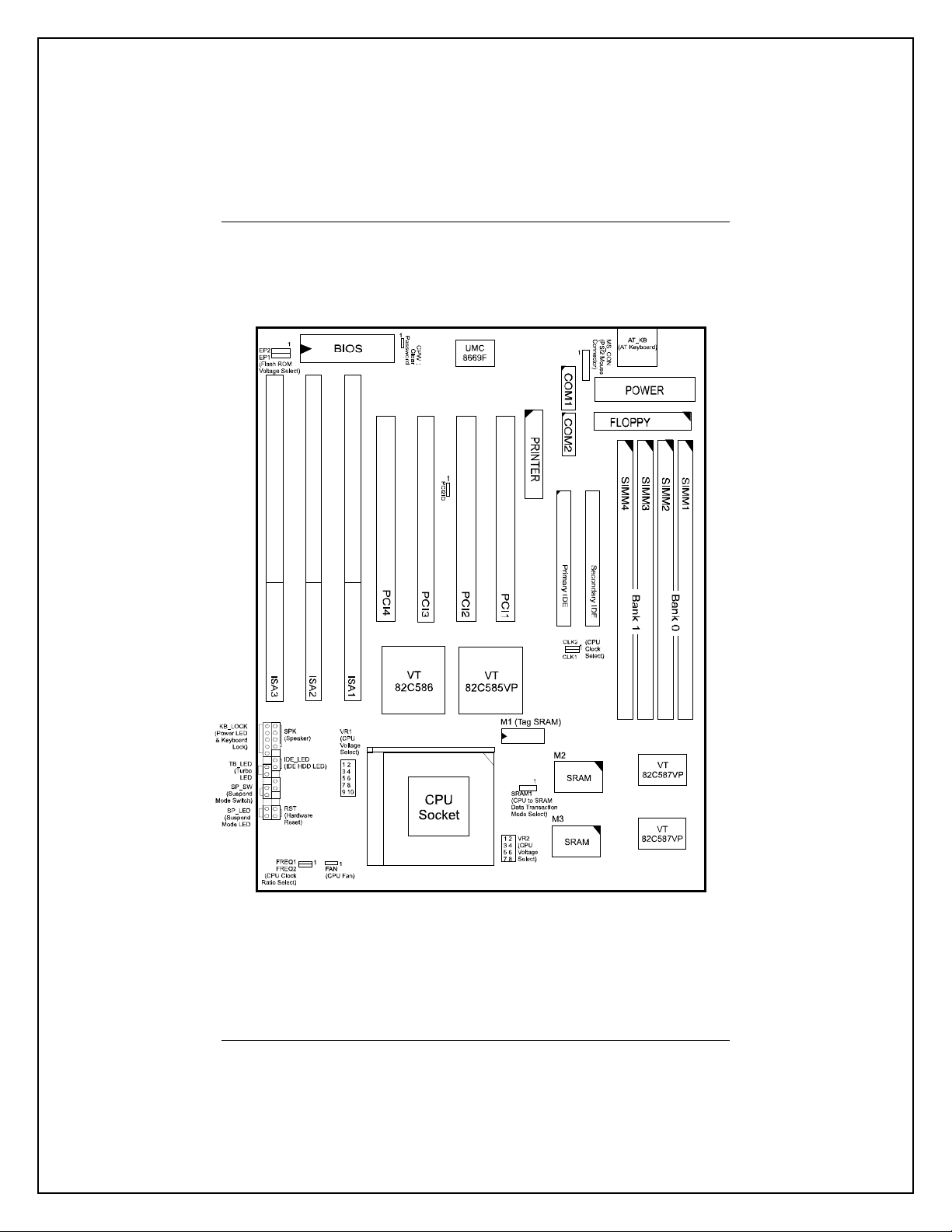
Mainboard Layout.................................................................................. 4
1). Set System Jumpers.......................................................................... 5
Flash ROM Voltage Select: EP1 and EP2 .............................. 5
CPU to SRAM Data Write Mode Selection: SRAM1.............. 5
Clear Password: CPW............................................................ 6
PCI 2 ID: PCI2ID................................................................... 6
2). Install DRAM Modules..................................................................... 7
DRAM Configuration.................................................................... 7
Installation Instructions................................................................. 8
Remove SIMMs............................................................................ 8
Cache Memory.............................................................................. 9
3). Install the CPUs................................................................................ 10
CPU to Bus Frequency Ratio:
FREQ1 and FREQ2............................................................... 11
CPU External Clock (Bus) Frequency: CLK1 and CLK2........ 12
CPU Voltage Selection:VR1 and VR2................................... 13
CPU Voltage Markings.......................................................... 14
Installation of Cyrix (or IBM) 6x86 CPU Fan......................... 15
4). Connect Cables and Power Supply.................................................... 16
Serial Port Connectors: COM1 and COM2............................. 16
CPU Fan Connectors: FAN.................................................... 16
Block Connector.................................................................... 17
Power Connector: POWER .................................................... 18
Chapter 3 Award BIOS Setup
CMOS Setup Utility............................................................................... 19
Standard CMOS Setup........................................................................... 20
BIOS Features Setup.............................................................................. 22
Chipset Features Setup........................................................................... 25
Power Management Setup...................................................................... 28
Table of Contents

VA-501 Mainboard Manual
ii
PCI Configuration Setup......................................................................... 31
PnP Configuration Setup........................................................................ 33
Load BIOS Defaults............................................................................... 34
Load Setup Defaults............................................................................... 34
Supervisor/User Password...................................................................... 34
IDE HDD Auto Detection....................................................................... 35
Save and Exit Setup............................................................................... 36
Exit without Saving................................................................................ 36

1
Main Features
The VA-501 mainboard comes with the following high-performance features:
■Easy Installation
Award BIOS with support for Plug and Play, auto detection of Hard Drive
and IDE features, MS Windows 95 and Windows NT compatible.
■Flexible Processor Support
The onboard 321-pin ZIF socket supports Intel Pentium (P54C) CPU speed
75/90/100/120/133/150/166/180/200 MHz processors / P54CTB.
Cyrix 6x86-P120+ (100 MHz) / 6x86-P133+ (110 MHz) / 6x86-P150+
(120 MHz) / 6x86-P166+ (133 MHz) processors.
IBM 6x86-P120+ (100 MHz) / 6x86-P133+ (110 MHz) / 6x86-P150+
(120 MHz) / 6x86-P166+ (133 MHz) processors.
AMD K5-PR75 (75 MHz) / K5-PR90 (90 MHz) / K5-PR100 (100 MHz) /
K5-PR120 (90 MHz) / K5-PR133 (100 MHz) / K5-PR150 (120 MHz) /
K5-PR166 (133 MHz) processors.
■Leading Edge Chipset
VIA Apollo 580VP chipset, including a CPU interface controller,
advanced
cache controller, integrated DRAM controller, synchronous ISA bus
controller, PCI local bus interface, integrated power management unit.
■Ultra-fast Level II Cache
Supports onboard 256KB/512KB synchronous PBSRAM direct-mapped
write-back cache memory.
■Versatile Main Memory Support
Accepts up to 64MB RAM in two banks using 72-pin SIMM modules of
4, 8, 16, 32MB with support for EDO and Fast Page Mode memory.
Chapter 1

VA-501 Mainboard Manual
2
■ISA & PCI Expansion Slots
Three 16-bit ISA and four 32-bit PCI expansion slots provide all the
room you need to install a full range of add-on cards.
■Enhanced PCI Bus Master IDE Controller
Integrated Enhanced PCI local bus IDE controller with two connectors
supports up to four IDE devices such as Hard Disk, CD-ROM or Tape
Backup drives via two channels for high speed data throughput. This
controller supports PIO Modes 3 and 4, and DMA Mode 2 for optimized
system performance.
■Super Multi I/O
Integrated UMC 669/LGS Prime 3C chipset features two 16550A UART
compatible serial ports, one EPP/ECP capable parallel port, and one
Floppy
Disk Drive connector.

3
Installation Procedures
The VA-501 has several user-adjustable jumpers on the board that allow you to
configure your system to suit your requirements. This chapter contains
information on the various jumper settings on your mainboard.
To set up your computer, you should follow these installation steps:
■Step 1 -
Set system jumpers
■Step 2 -
Install DRAM modules
■Step 3 -
Install the CPU
■Step 4 -
Connect cables and power supply
■Step 5 -
Set up BIOS feature (Please read Chapter Three.)
Chapter 2
VA-501 Mainboard Manual
4
Mainboard Layout

Installation Procedures
5
1). Set System Jumpers
NOTE : Users are not encouraged to change the jumper settings not listed in
this manual. Changing the jumper settings improperly may adversely affect
system performance.
Flash ROM Voltage Select: EP1 and EP2
These two jumpers allow you to select the different voltages of the flash ROM.
CPU to SRAM Data Write Mode Selection: SRAM1
This jumper allows you to select the CPU to SRAM data read/write mode.
Also, you need to configure the BIOS feature, Linear Bust Mode, in Page 26.
Please refer to it.

VA-501 Mainboard Manual
6
Clear Password: CPW
The password clear jumper lets you set the password configuration to
“Enabled” or “Disabled”. You may need to enable password clear if forget your
password.
PCI 2 ID: PCI2ID
This setting is provided to allow you to install more than PCI add-on card
released before the launch of the PCI Encoding Standard in 1993.
NOTE : Please be aware that this feature is only provided for reasons of
convenience and it is only in rare cases that the user needs to alter the default
setting. Please consult your dealer for further information.

Installation Procedures
7
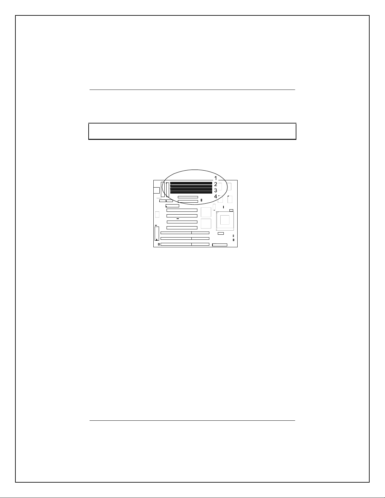
2). Install DRAM Modules
The VA-501 supports standard Fast Page Mode and Extended Data Out
DRAM; accommodates onboard memory from 8 to 64MB using SIMMs. The
mainboard has two memory banks - Bank 0 and Bank 1 which can use different
types of SIMMs. However, you must populate each memory bank with the same
type of SIMM.
DRAM Configuration
DRAM modules can be installed in a variety of configurations as shown below:
TOTAL MEMORY BANK 0 (72-PIN X 2) BANK 1 (72-PIN X 2)
8MB 4MB & 4MB
16MB 8MB & 8MB
4MB & 4MB 4MB & 4MB
24MB 8MB & 8MB 4MB & 4MB
32MB 8MB & 8MB 8MB & 8MB
16MB & 16MB
64MB 16MB & 16MB 16MB & 16MB
32MB & 32MB
NOTE : All memory banks use 72-pin memory modules.
VA-501 Mainboard Manual
8
Installation Instructions
NOTE : Always observe static electricity precautions. See “Handling
Precautions” at the start of this manual.
1. Locate the SIMM on the mainboard.
2. Carefully fit a SIMM at a 45 degree angle into each of the empty sockets
to be populated. All the SIMMs should be facing the same direction.
3. Swing each SIMM into its upright, locked position. When locking a SIMM
in place, push on each end of the SIMM - do not push in the middle.
Remove SIMMs
To remove the SIMMs, pull the retaining latch on both ends of the socket and
reverse the procedure above.
Installation Procedures
9
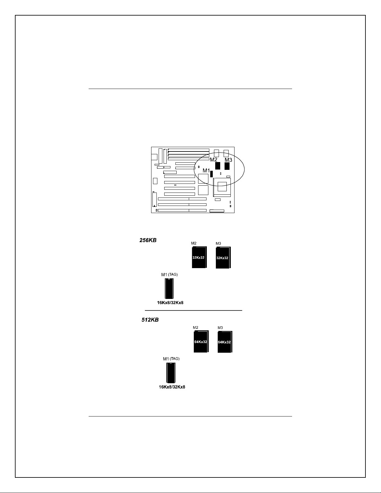
Cache Memory
The VA-501 provides the onboard 256KB/512KB cache SRAMs. The
corresponding jumper settings are shown below.
.

VA-501 Mainboard Manual
10
3). Install the CPUs
The VA-501 provides one onboard Zero Insertion Force (ZIF) socket for the
processor.
CAUTION :
1. Always turn the system power off before installing or removing
any device.
2. Always observe static electricity precautions.
3. Inserting the CPU chip incorrectly may damage the chip.
To install the CPU, do the following:
1. Lift the lever on the side of the CPU socket.
2. Handle the chip by its edges and try not to touch any of the pins.
3. Place the CPU in the socket. The chip has a notch to correctly orientate the
chip. Align the notch with pin one of the socket. Pin one locates around the
triangular blank area. Do not force the chip. The CPU should slide easily
into the socket.
4. Swing the lever to the down position to lock the CPU in place.
5. See the following section for information on the CPU jumper settings.
To remove the CPU, simply reverse the procedures introduced above.
Installation Procedures
11
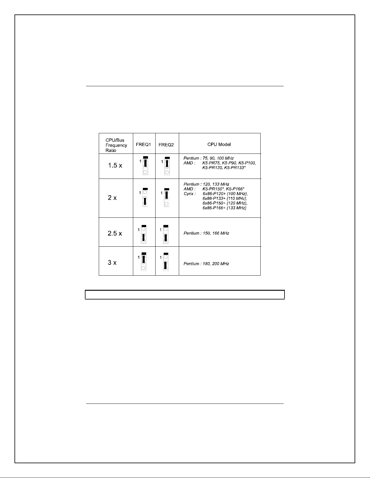
CPU to Bus Frequency Ratio: FREQ1 and FREQ2
These two jumpers are used to configure the ratio of the CPU frequency to the
bus clock.
NOTE : * This CPU had not yet been tested when this manual was printed.

VA-501 Mainboard Manual
12
CPU External Clock (Bus) Frequency: CLK1 and CLK2
The table below shows the jumper settings for the different CPU speed
configurations.
NOTE : * This CPU had not yet been tested when this manual was printed.

Installation Procedures
13
CPU Voltage Selection: VR1 and VR2
VA-501 Mainboard Manual
14
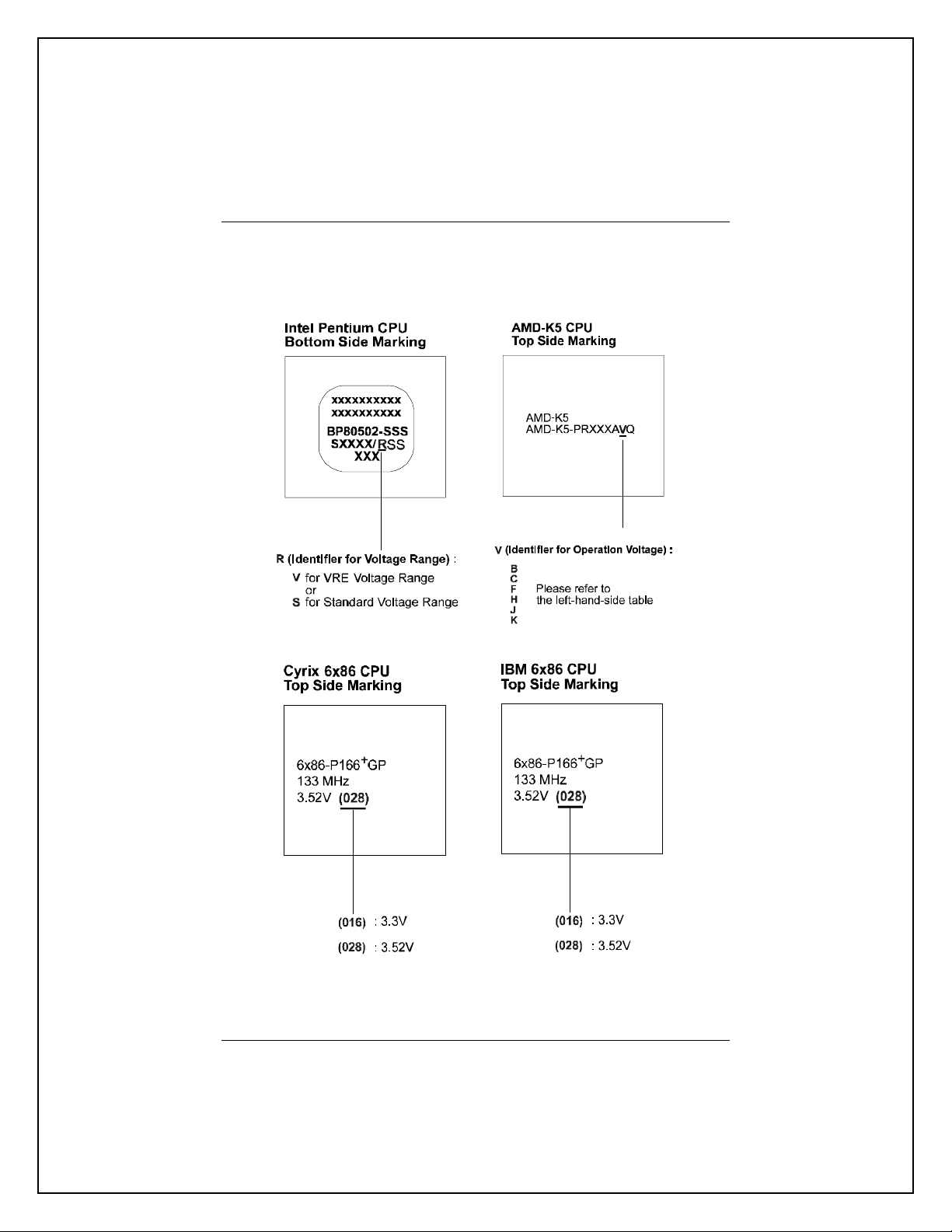
CPU Voltage Markings

Installation Procedures
15
Installation of Cyrix (or IBM) 6x86 CPU Fan
CAUTION : When you install a Cyrix (or IBM) 6x86 CPU fan, please pay
attention to the direction of the air flow. Make sure the air flow is in the
direction of the regulator; otherwise, the system may overheat.
We recommended that you use one of the following two CPU fans for the Cyrix
(or IBM) 6x86 CPU when install the fan on the mainboard.
1). Supplier : BIRCHTECK, Taiwan (Phone : 886-2-7935677).
Model Number - BEC6x86B1.
2). Supplier : Thermalloy, USA (Phone : 214-243-4321).
Model Number : 20832 (customer should request NMB-B50
Fan).
This is a 90-degree rotated fan and is recommended for
installation
on the mainboard.
For further information, please contact your local dealer.
For stable system performance, make sure that the air flow blows directly, as
shown below, toward the regulator so as to lower the temperature of the
regulator.
VA-501 Mainboard Manual
16
4). Connect Cables and Power Supply
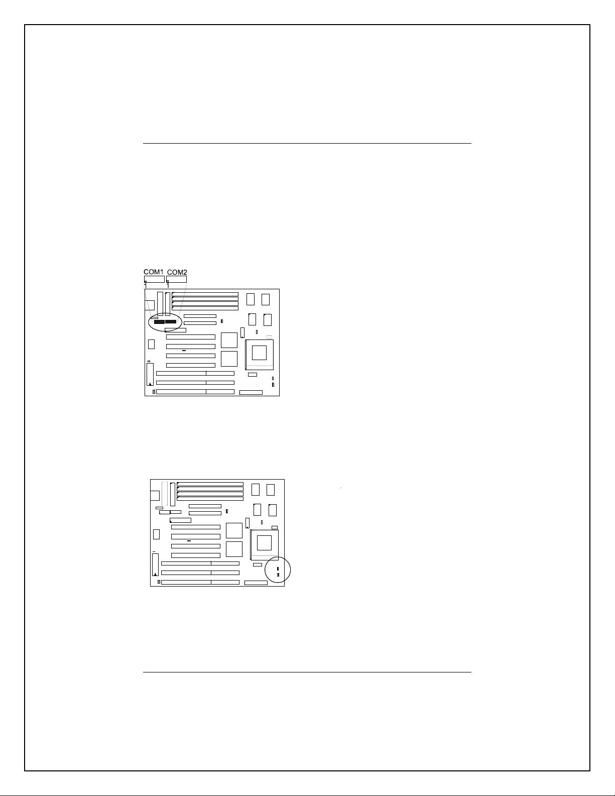
Serial Port Connectors: COM1 and COM2
This two 9 pin D-Sub male connectors allow you to connect with your devices
that take serial ports, such as a serial mouse or a modem. Usually, the serial
mouse is connected to COM1, and the modem is connected to COM2.
CPU Fan Connector: FAN
This two 3-pin connector is connected to the CPU fan.

Installation Procedures
17
Block Connector
This block connector includes: PW_LED, KB_LOCK, TB_LED, SP_SW,
SP_LED, SPK, IDE_LED, RST connectors.
Item Connector Pin Type Feature
A PW_LED 2-pin male indicates the system power status
B KB_LOCK 2-pin male allows the keyboard to access the system
C TB_LED 2-pin male indicates the system speed is in normal or
turbo speed
D SP_SW 2-pin male Suspend Mode switch
E SP_LED 2-pin male indicates the system into Suspend Mode
when LED lit
F SPK 4-pin male connects to speaker
G IDE_LED 2-pin male indicates the IDE HDD I/O access LED lit
H RST 2-pin male allows you to reset the system
Table of contents
Other FIC Motherboard manuals


