FIC CE31-A User manual

CE31-A
MAINBOARD
MANUAL
DOC No.: 098B09
Rev. : A0
Date : 4, 1999
Part No. : 25-10936-20

Handling Precautions
Warning:
1. Static electricity may cause damage to the integrated circuits on
the motherboard. Before handling any motherboard outside of its
protective packaging, ensure that there is no static electric charge
in your body.
2. There is a danger of explosion if the battery is incorrectly
replaced. Replace only with the same or an equivalent type
recommended by the manufacturer.
3. Discard used batteries according to the manufacturer’s
instructions.
Observe the following basic precautions when handling the motherboard
or other computer components:
nWear a static wrist strap which fits around your wrist and is
connected to a natural earth ground.
nTouch a grounded or anti-static surface or a metal fixture such as a
water pipe.
nAvoid contacting the components on add-on cards, motherboards,
and modules with the golden fingers connectors plugged into the
expansion slot. It is best to handle system components by their
monting brackets.
The above methods prevent static build-up and cause it to be discharged
properly.
Trademark
All trademarks mentioned in this manual are registered properly of
the respective owners.
Handling Precautions
Thismanualmaynot,inwholeorinpart,bephotocopied,reproduced,
transcribed, translated, or transmitted in whatever form without the
written consent of the manufacturer, except for copies retained by the
purchaser for personal archival purposes.
Notice

i
TableofContents
Table of Contents
Chapter 1 Overview
Package Checklist .......................................................................... 1-2
TheCE31-AMainboard ............................................................ 1-3
Main Features................................................................................ 1-4
Intelligent Properties...................................................................... 1-6
ACPIReady ................................................................................... 1-7
Chapter 2 Installation Procedures
1). Set System Jumpers ................................................................. 2-2
QuickReference............................................................................. 2-3
Mainboard Layout .................................................................... 2-7
ClearPassword:CLR_PWD .............................................. 2-9
ClearCMOS:J4 ................................................................. 2-9
InternalUSB Port Enable:J3.............................................. 2-10
2). Install RAM Modules .............................................................. 2-10
SDRAM..................................................................................... 2-10
RAM Module Configuration..................................................... 2-11
Install and Remove DIMMs ...................................................... 2-11
3).Install the CPU .......................................................................... 2-12
4). Install Expansion Cards............................................................. 2-13
5). Connect Devices ....................................................................... 2-15
FloppyDiskette Drive Connector:FLOPPY ...................... 2-15
IDEHDDDevice Connectors:PRIMARY,SECONDARY .. 2-16
ATX Power Connector: POWER ....................................... 2-16
CPUFan Connector: FAN1 ............................................... 2-17
Wake-On-LAN Connector: WOL ...................................... 2-17
Front Panel Block Connector ............................................ 2-18
PCIAudio Card Connector:SB_LINK .............................. 2-19
InfraredConnector: IR....................................................... 2-19
PS/2 Keyboard and Mouse Connector: KB, MS ............... 2-20
UniversalSerial BusConnectors: USB0,USB1, CONN1 ... 2-20
PrinterConnector: LPT...................................................... 2-21
SerialPort Connectors: COM1,COM2 .............................. 2-21
Joystick/MIDIConnector: GAME..................................... 2-22
AudioI/O Jacks: L_OUT,L_IN, MIC_IN .......................... 2-22
Video Graphics AcceleartorConnector: VGA ................... 2-23

ii
CE31-AMainboardManual
Chapter 3 BIOS Setup
CMOSSetup Utility ....................................................................... 3-1
Standard CMOS Setup................................................................... 3-2
Hard Disk Configurations.......................................................... 3-2
Software Turbo Speed............................................................... 3-3
BIOS Features Setup...................................................................... 3-3
Chipset Features Setup.................................................................. 3-6
Power Management Setup ............................................................. 3-9
PNP/PCIConfiguration .................................................................. 3-13
LoadBIOS Defaults ....................................................................... 3-14
Load Setup Defaults ...................................................................... 3-14
Integrated Peripherals.................................................................... 3-15
Supervisor/User Password ............................................................ 3-19
IDE HDD Auto Detection .............................................................. 3-19
Save and Exit Setup ....................................................................... 3-19
Exitwithout Saving ........................................................................ 3-20
Chapter 4 FAQs
GeneralFAQs................................................................................. 4-1
BIOSFAQs .................................................................................... 4-5
Windows 98 FAQs ......................................................................... 4-7
Windows 95 FAQs ......................................................................... 4-8
IntelCPU FAQs ............................................................................. 4-9

1 - 1
Overview
Overview
Chapter 1
TheCE31-A isa MicroATX sized Socket 370motherboard with onboard Video
and Audio, and support for Ultra DMA/66. The CE31-A supports the Intel®
Celeron PPGA 300-500 MHz processor at 66MHz Front side bus, and is ready
to support 100MHz Front Side Bus in the event of any future CPU upgrades.
Based around the SIS Eagle chipset, the CE31-A is a feature rich mainboard
offering the very latest in quality onboard integrated functions.
Quality stereo sound is provided by the ESS Solo-1 onboard audio chip, which
is equipped with Headphone AMP, while graphics capabilities are provided
by the SIS 6326 2D/3D, which is embedded in the North Bridge. The option of
DVD playback software and a TV-out connection, allows DVD playback on
a TV, instead of just a monitor. This special feature is enabled by FIC’s unique
licensing agreement with CSS.
With support for Ultra DMA/66 and its high-speed interface, hard drive per-
formance and data transfer speeds are significantly increased. The CE31-A
has 2 DIMM, providing up to 1 GB of SDRAM, and has 3 PCI and 1 ISA
expansion slot. UMA mode can be selected through the BIOS at either 4MB or
8MB, while non UMA mode is offered as a manufacturing option. The CE31-
Ais ACPI ready,ensuring improvedpower management, and is PC98and Y2K
compliant. Other key features of the CE31-A are Keyboard/Mouse Power On
and CD Pro with enhanced drivers. A hardware monitoring facility provides
effective system control and protection.
The CE31-A offers a complete set of standard I/O features, such as 2 serial
ports, 1 parallel port, 1 PS/2 mouse and keyboard connector and 2 USB con-
nectors. There are also connectors for 1 VGA, 1 media, mono-in for modem,
CD-in,Wake-on-LAN and Wake-on-Ring.

1 - 2
CE31-AMainboardManual
Package Checklist
If you discover any item below was damaged or lost, please contact your
vendor.
Ö Themainboard
Ö Thisuser manual
Ö Onefloppy diskdrive cable
Ö Oneprinter and COM1cable
Ö One HDD cable
Ö One COM2 cable
Ö One USB cable (optional)
Ö Software utilities

1 - 3
Overview
The CE31-A Mainboard

1 - 4
CE31-AMainboardManual
Main Features
■Easy Installation
||BIOS with support for Plug and Play, auto detection of IDE hard drives,
||LS-120|drives,IDE ZIPdrives, Windows95, Windows98,Windows NT,
||andOS/2.
■Leading Edge Chipset
SiS Eagle chipset includes a CPU interface controller, integrated memory
controller, integrated power management unit, concurrent PCI (PCI v.2.0,
2.1,2.2), 3D video, IDE and ISA bus controller.
■Flexible Processor Support
Onboard Socket 370 supports leading-edge processors:
Celeron™PPGAprocessors 300A/333/366/400/433/466/500MHz and up.
|■Various External Bus and CPU/Bus Frequency Ratio Support
The board supports the Bus frequency of 66 / 75 / 83 / 90 / 95 / 100 / 112
/124 / 133MHz and theCPU/Bus frequencyratio of2x /2.5x /3x / 3.5x / 4x
/ 4.5x / 5x / 5.5x / 6x / 6.5x / 7x / 7.5x / 8x by a switching voltage regulator
whichaccepts 1.8V to2.8V.|||(Please read InstalltheCPU in Chapter2 for
moreinformation).
■Versatile Main Memory Support
Accepts up to 1GB RAM using two DIMMs of 8, 16, 32, 64, 128, 256,
512MBwith support forlightning-fast SDRAM (66/100MHz).
■ISA and PCI Expansion Slots
One 16-bit ISA Bus and three 32-bit PCI Bus expansion slots provide the
room to install a full range of add-on cards.
■Onboard IrDA Connector
An IrDA connector for wireless infrared connections is available.

1 - 5
Overview
■Enhanced PCI Bus Master IDE Controller with Ultra DMA/33 and
Ultra DMA/66 Support
Integrated Enhanced PCI Bus Master IDE controller features two dual-
channel connectors that accept up to four Enhanced IDE devices, includ-
ing CD-ROM and Tape Backup Drives, as well as Hard Disk Drives sup-
portingthe new UltraDMA/66 protocol. Standard PIO Mode 3, PIO Mode
4, DMA Mode 2, DMA Mode 4 devices are also supported.
■USB Support
A fly cable comes with the board for allowing convenient, high-speed
Plug and Play connections (up to four USB ports) to the growing number
of USB compliant external peripheral devices on the market.
■■
■■
■Remote Wake-Up Support
One LAN wake-up connector, WOL, supports LAN cards equipped for
remote wake-up functionality; also, an additional Wake-On-Ring connec-
tor awakes the system while the ring signal via modem.
■■
■■
■Super Multi Input/Output (I/O) Support
IntegratedPlug and Play multi-I/O chipset features two high-speed UART
16550 compatible serial ports, one IR connector, one EPP/ECP capable
parallel port, and one FDD connector.
■■
■■
■SB-LINKÔfor theAudio Card with PCI Bus
The 2x3 pin SB-LINKÔheader accepts the Creative CT4600 series PCI
audio cards with PCI solution to connect the Legacy Sound BlasterÒ
compatible audio to the PCI bus.
■■
■■
■Compact ESS Solo-1 Audio Subsystem for Sound and Game
The onboard audio provides DirectMusic accelerator. It also provides
OPL3,Sound BlasterPro, MPU401UARTmodeand Joystick function for
various PC games on real DOS mode that without software drivers. The
board came with three audio jacks: MIC_IN, L_IN, L_OUT; and one con-
nector for joystick with MIDI interface.

1 - 6
CE31-AMainboardManual
Intelligent Properties
This mainboard comes equipped with the most advanced new features that
not only optimize the performance of the latest processors but also enhance
the manageablity, power management capabilities, and user-friendliness of
your system. This section provides detailed information on these features,
and how they are implemented on the mainboard.
■■
■■
■OptimizedCeleronÔPPGA Processor Performance
The mainboard utilizes the advanced features of the SiS Eagle chipset to
optimize the unrivaled performance of the CeleronÔPPGA processor
with MMXÔtechnology, allowing you to enjoy a richer video, audio,
digitalimaging and communicationsexperience from the latest generation
ofmultimedia software.
■Capability of Conference via Modem
The board equipped a MONO connector to allow users to talk with other
people at remote end via a modem.
■Connection with a Television (Optional)
The manufacturing optional connector, TV1, makes use of a television as
a monitor for software games and other tasks by a cable from the board to
theTV.

1 - 7
Overview
ACPI Ready
Thismainboard fully implements the new ACPI (Advanced Configuration and
PowerInterface)1.0 HardwareandBIOS requirement.Ifyou installACPIaware
operating system, such as Windows 98, you fully utilized the power saving
under ACPI.
It is compatible with all other none ACPI operating systems. If you want to
setup ACPI feature under Windows 98, please follow the description below:
Run Windows 98 setup by using setup/p j on the command line for installing
Windows 98 with the ACPI control feature.
If you type setup without the parameter /p j, Windows 98 will be installed as
APM, PnP mode, no ACPI will be used.
For more detail information, please visit the web site of Microsoft. Its address
is:www.microsoft.com/hwtest/.
The major features of ACPI were listed as follows:
■Soft-Off Support
The mainboard’s Soft-Off feature allows you to turn off your computer
using the operating system. This feature requires a power supply witha
soft-off power controller.
■RemoteRing-On
The Remote Ring-On function allows your computer to be turned on
remotely via a modem while it is in sleep mode. This feature is particularly
usefully when you are expecting a fax late night and leave only your
modem on to minimize power consumption. As soon as possible the phone
rings, the modem automatically turn on the system, which answers the
phone and downloads the fax. Then the computer shuts off again, thereby
minimizing its consumption of power. The Remote Ring-On function
requires a power supply with a soft-off power controller.
■RTCAlarm
The RTC alarm feature allows you to preset the computer to wake-up at a
certaintime allowing you to implement a number of useful functions, such
as automatically sending out a fax late at night.

1 - 8
CE31-AMainboardManual
This Page Left Blank for Note

2 - 1
Installation Procedures
Chapter 2
Installation Procedures
The mainboard has several user-adjustable jumpers on the board that allow you to
configure your system to suit your requirements. This chapter contains information
on the various jumper settings on your mainboard.
To set up your computer, you must complete the following steps:
■ Step 1 - Set system jumpers
■ Step 2 - Install system RAM modules
■ Step 3 - Install the Central Processing Unit (CPU)
■ Step 4 - Install expansion cards
■ Step 5 - Connect ribbon cables, cabinet wires, and power supply
■ Step 6 - Set up BIOS software (see Chapter Three)
■ Step 7 - Set up supporting software tools
WARNING: Excessive torque may damage the mainboard. When
using an electric screwdriver on the mainboard, make sure that
the torque is set to the allowable range of 5.0 ~ 8.0kg/cm.
Mainboard components contain very delicate Integrated Circuit
(IC) chips. To prevent static electricity from harming any of the
mainboard’s sensitive components, you should follow some
precautions whenever working on the computer:
1. Unplug the computer when working on the inside.
2. Hold components by the edges and try not to touch the IC
||||chips, leads, or circuitry.
3. Wear an anti-static wrist strap which fits around the wrist.
4. Place components on a grounded anti-static pad or on the bag
that came with the component whenever the components are
separated from the system.
2 - 2
CE31-AMainboardManual
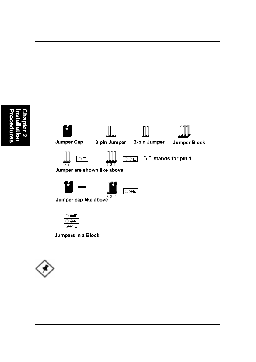
1). Set System Jumpers
Jumpers are used to select the operation modes for your system. Some jump-
ers on the board have three metal pins with each pin representing a different
function. A “1” is written besides pin 1 on jumpers with three pins. To set a
jumper, a black cap containing metal contacts is placed over the jumper pin/s
according to the required configuration. A jumper is said to beshorted when
the black cap has been placed on one or two of its pins. The types of jumpers
used in this manual are shown below:
NOTE: Users are not encouraged to change the jumper settings
not listed in this manual. Changing the jumper settings improperly
may adversely affect system performance.
2 - 3
Installation Procedures
This Chapter is intended to aid quick and easy installation.
In the event that more detailed information is required, please
consult the Installation Procedures Chapter.

2 - 4
CE31-AMainboardManual

2 - 5
Installation Procedures
1). Clear CMOS, Clear Password
2). CPU Fan Installation
This connector is linked to the CPU fan. When the system is in suspend mode, the
CPU fan will turn off; when it reverts back to full on mode, the fan will turn back on.
Without sufficient air circulation, the CPU may overheat and cause damage to
both the CPU and the mainboard.
Damage may occur to the mainboard and/or the CPU fan if these pins are
incorrectlyused. These are not jumpers, do notplacejumper caps over these
pins.
3). Front Panel Block
Cable Connection
4). Other Enabled/Disabled Jumpers

2 - 6
CE31-AMainboardManual
5). Load BIOS Setup Default
Load BIOS Defaults
BIOS defaults contain the most appropriate values of the system parameters
thatallow minimum systemperformance. The OEM manufacturer may change
the defaults through MODBIN before the binary image burns into the ROM.
Load Setup Defaults
Selecting this field loads the factory defaults for BIOS and Chipset Features
which the system automatically detects.
1. Formata bootable system floppy diskette by typing the command format
a:/sin command mode.
2. Visit the the web site of the vendor and visit the BIOS Update page in the
related Technical Support section.
3. Select the BIOS file you need and download it to your bootable floppy
diskette.
4. Insert the bootable diskette containing the BIOS file into the floppy dis-
kette drive.
5. Assuming that the floppy diskette drive is A, reboot the system by using
the A: drive. At the A: > prompt, run the BIOS upgraded file by executing
the Flash BIOS utility and the BIOS file with its appropriate extension.
Do not turn off or reset the computer during the flash process or if there is
a problem.
6). How to Upgrade BIOS

2 - 7
Installation Procedures
Mainboard Layout

2 - 8
CE31-AMainboardManual
ONBOARDMARK MEANING PAGE
Jumpers
J4 Clear CMOS Data 2 - 9
CLR_PWD Clear Password 2 - 9
J3 Internal USB Port Enable 2 - 10
Slots
DIMM1/2 DIMM Memory Module Support 2 - 11
PCI1/2/3 PCI Bus Expansion Slot (32-bit) 2 - 14
ISA1 ISA Bus Expansion Slot (16-bit) 2 - 14
Connectors
FLOPPY Floppy Diskette Drive Connector 2 - 15
PRIMARY, SECONDARY IDE HDD Device Connectors 2 - 16
POWER ATX Power Connector 2 - 16
FAN1 CPU Fan Connector 2 - 17
WOL Wake on LAN Connector 2 - 17
Front Panel Block Connectors for LEDs and
SB_LINK PCI Audio Card Connector 2 - 19
IR Infrared Port Module Connector 2 - 19
KB/MS PS/2 Keyboard/Mouse Connector 2 - 20
USB0/1, CONN1 Universal Serial Bus Connector 2 - 20
LPT (Parallel Port) Printer Connector 2 - 21
COM1, COM2 Serial Port Connectors 2 - 21
GAME Joystick/MIDI Connector 2 - 22
L_OUT, L_IN, MIC_IN Audio I/O Jacks 2 - 22
VGA Video Graphics Accelerator 2 - 23
Connector Switches on Front Panel 2 - 18
Table of contents
Other FIC Motherboard manuals


