FIC AZ11 User manual

AZ11
MAINBOARD
MANUAL
DOC No.: M00401
Rev. : A1
Date : 6, 2000
Part No. : 25-11521-21

Handling Precautions
Warning:
1. Static electricity may cause damage to the integrated circuits on
the motherboard. Before handling any motherboard outside of its
protective packaging, ensure that there is no static electric charge
in your body.
2. There is a danger of explosion if the battery is incorrectly
replaced. Replace only with the same or an equivalent type
recommended by the manufacturer.
3. Discard used batteries according to the manufacturer’s
instructions.
Observe the following basic precautions when handling the motherboard
or other computer components:
nWear a static wrist strap which fits around your wrist and is
connected to a natural earth ground.
nTouch a grounded or anti-static surface or a metal fixture such as a
water pipe.
nAvoid contacting the components on add-on cards, motherboards,
and modules with the golden fingers connectors plugged into the
expansion slot. It is best to handle system components by their
monting brackets.
The above methods prevent static build-up and cause it to be discharged
properly.
Trademark
All trademarks mentioned in this manual are registered properly of
the respective owners.
Handling Precautions
Thismanualmaynot,inwholeorinpart,bephotocopied,reproduced,
transcribed, translated, or transmitted in whatever form without the
written consent of the manufacturer, except for copies retained by the
purchaser for personal archival purposes.
Notice

i
TableofContents
Table of Contents
Chapter 1 Overview
Package Checklist .......................................................................... 1-2
The AZ11 Mainboard................................................................ 1-3
Main Features................................................................................ 1-4
ACPIReady ................................................................................... 1-6
FICUniqueInnovationforUsersII(NOVUSII) -
Enhanced Mainboard Features and System Support .................... 1-6
Chapter 2 Installation Procedures
QuickReference (from Page2-2 to 2-4) .......................................... 2-2
Mainboard Layout .................................................................... 2-2
1).Clear CMOS,Over VoltageDriving............................... 2-3
2). Front Panel Block Cable Connection ............................ 2-4
3).CPU Fan Installation .................................................... 2-4
1). Set System Jumpers .................................................................. 2-5
ClearCMOS:CLR_CMOS ................................................. 2-6
Enabling Over Voltage Driving: Magic Tuner ................... 2-6
2). Install RAM Modules .............................................................. 2-7
Install and Remove DIMMs .............................................. 2-7
3).Install the CPU .......................................................................... 2-8
4). Install Expansion Cards............................................................. 2-9
5). Connect Devices ....................................................................... 2-10
Floppy Diskette Drive Connector: FDD ............................ 2-10
IDEHDD DeviceConnectors: PRIMARY,SECONDARY .. 2-11
ATX Power Connector: ATX_PWR .................................. 2-11
CPUFan Connector:CPU_FAN ........................................ 2-12
System Case Fan Connectors: CHS_FAN, SYS_FAN ....... 2-12
CDAudioo-In Connectors: CD_IN1, CD_IN2.................. 2-13
FrontPanel Block Connector: FPNL.................................. 2-13
PS/2 Keyboard and Mouse Connector: PS2_KB, PS2_MS 2-15
Universal Serial Bus Connectors: Rear USBs, Front USBs 2-15
PrinterConnector: LPT...................................................... 2-16
Serial Port Connectors: COM ............................................ 2-16
AudioI/O Jacks:LINE_OUT,LINE_IN, MIC_IN .............. 2-17
NOVUSII ModuleConnector: NOVUSII ......................... 2-17

ii
AZ11MainboardManual
Chapter 3 BIOS Setup
CMOSSetup Utility ....................................................................... 3-1
Standard CMOS Setup................................................................... 3-2
Hard Disk Configurations.......................................................... 3-2
Advanced BIOS Features .............................................................. 3-3
Advanced Chipset Features .......................................................... 3-6
Integrated Peripherals .................................................................... 3-11
Power Management Setup ............................................................. 3-15
PNP/PCIConfigurations ................................................................ 3-20
PC Health Status ............................................................................ 3-21
Frequency/Voltage Control ............................................................ 3-22
LoadFail-Safe Defaults.................................................................. 3-23
LoadOptimized Defaults................................................................ 3-23
Supervisor/User Password ............................................................ 3-24
Save and Exit Setup ....................................................................... 3-25
Exitwithout Saving ........................................................................ 3-25
Quick Reference (German) G-1
Quick Reference (French) F-1
Quick Reference (Spanish) S-1
Quick Reference (Japanese) J-1
Quick Reference (Chinese) C-1
Quick Reference (Simplified Chinese ) SC-1

1 - 1
Overview
Overview
Chapter 1
The new Socket A 1stMainboard AZ11 is an ATX sized motherboard support-
ing the latest generation of AMD Athlon and Duron processors at industry
leading speeds. By utilizing DDR ( Double Data Rate ) transfer rate the 100
MHz AMD Athlon system bus effectively reaches speeds of 200 MHz. The
AMD Athlon processor offers high-performance cache technology, including
128KBof on-chip level one (L1), while the Duron featuresfull-speed, on-chip
L2 cache memory, and enhanced 3DNow!™ technology. The 1stMainboard
AZ11 has 3 DIMM, for up to 1.5 GB of SDRAM, utilizes the latest PC133
SDRAM technology and is equipped with ECC memory support.
The 1stMainboard AZ11 is based around the high performance KT133 chipset
comprisedof VIA VT8363 systemcontroller for theNorth Bridge, andthe VIA
686A ( Super South ). The KT133’s support for AGP 4x provides the end-user
a photo-realistic 3D experience suitable for the most robust 3D games and
software environments. Onboard AC97 sound ensures high quality audio, but
with the option of being disabled through the BIOS.
The 1stMainboard AZ11 also comes equipped with the new NOVUS II range
of innovative features that assist in the installation and maintenance of your
1stMainboard. The features include Easy Key, which provides instant key-
board access to the BIOS for adjustments to Clock and Default settings and
LogoGenie, which allows you to create your own customized logo to be dis-
played during system boot up. The BIOS Guardian is anAnti Virus utility that
prevents viruses from damaging your system BIOS and rendering your sys-
tem inoperative. Clockometer is a user friendly Graphic User Interface (GUI)
that allows you to change clock speed settings directly, without having to
enterthe BIOS Sub-Menus. Moreover, audio alertII (mfg. optional) ,a friendly
onboard voice caution, will advice the error during system boot up.
Expansionis provided by1 AGPand 5 PCI slots.In addition, the1stMainboard
AZ11 is equipped with 2 dual channeled enhanced PCI bus master IDE con-
nectors. Standard I/O connections include 1 serial port, 1 parallel port, 1 PS/2
mouse and keyboard connector, 2 USB connectors, 2 front USB pin-headers
and 1 media connector ( Line-In, Line-Out, Mic-In).

1 - 2
AZ11MainboardManual
Package Checklist
If you discover any item below was damaged or lost, please contact your
vendor.
þThe mainboard þThis user manual
þOneFDD cable þOne HDD cable
þOneATA/66cable þAudio Alert II module (optional)
þTwo software CDs (CD Pro, CD Plus and its manual)
IMPORTANT:AMDCPUHEATSINKINSTALLATION
Be ware finish heat hink install. Before you boot system, please
check the heat sink is complete contact with die of CPU.
The poor contact will bring about over heat, it may damage your
processor.
Itisstrongly recommended that at least a200-wattATXpower pupply
be used for this motherboard. Make sure that your ATX power sup-
ply can supply at least 20 amperes on teh +5-Volt lead and 10ma
on the +5-Volt standby lead (+5VSB). Your system may become
unstable / unreliable and may experience difficulty in powering up if
your power supply is inadequate.

1 - 3
Overview
The AZ11 Mainboard

1 - 4
AZ11MainboardManual
Main Features
■Easy Installation
||BIOS with support for Plug and Play, auto detection of IDE hard drives,
||LS-120|drives, IDE ZIP drives, Windows 95, Windows 98, Windows NT
||4.0,Windows2000, |andOS/2.
■Leading Edge Chipset
VIAVT8363 and 686A (Super South) provideintegrated DRAM control-
lers with new Dynamic Power Management Architecture (DPMA), con-
currentPCI (2.2),AGP 1.0/2.0compliant and USB.
■Versatile Main Memory Support
Accepts up to 1.5GB DRAM using three DIMMs of 32, 64, 128, 256,
512MB with support for lightenning-fast SDRAM (100/133MHz). The
latestVirtualChannel Memory (VCM)SDRAM alsosupported.This board
allows the FSB and DRAM to be asynchronous.
■Enhanced PCI Bus Master IDE Controller with Ultra DMA/33 and
Ultra DMA/66 Support
Integrated Enhanced PCI Bus Master IDE controller features two dual-
channel connectors that up to four Enhanced IDE devices, including CD-
ROM and Tape Backup Drives, as well as Hard Disk Drives supporting
the new Ultra DMA/66 protocol. Standard PIO Mode 3, PIO Mode 4,
DMA Mode 2, DMA Mode 4 devices are also supported.
■AMD® Athlon™ Processors Support
Duron Socket A CPU 600/650/700/750MHz at 100MHz FSB with AMD
bus for double data transfer rate at 100MHz for an effective 200MHz
transfer rate.
Athlon Socket A CPU 750/800/850/900*/950*MHz and up to 1GHz*at
100MHz FSB with AMD Athlon bus for double data rate transfers at
100MHzfor effective 200MHztransfer rate.

1 - 5
Overview
■AGP and PCI Expansion Slots
One AGP Bus expansion slot and five PCI Bus expansion slots provided
the room to install a full range of add-on cards.
■Compact Onboard Audio Subsystem
Embeded in VIA 686A®, the audio processor offers an integrated PCI
audiocontroller,DOS games compatibleengine, and offersthe feature of
high-quality music synthesizer. The subsystem utilizes line-out, line-in,
and MIC mini-jack external jacks, one joystick port with MIDI interface.
■■
■■
■Super Multi Input/Output (I/O) Support
IntegratedPlug and Play multi-I/O chipset featuresone high-speed UART
16550 compatible serial port, one EPP/ECP capable parallel port, and one
FDD connector.
■■
■■
■Convenient Rear Panel USB Connection Support
Two USB ports integrated in the rear I/O panel with two manufacturing
optional USB front panel connections allow convenient and high-speed
Plug and Play connections to the growing number of USB compliant
peripheral devices on the market.
■■
■■
■Onboard Accelerated Graphics Port (AGP)
Themotherboard is installedone 32-bit AGPbus with adedicated 66MHz/
133MHzpath from the graphicscard to the system memoryoffering much
greater bandwidth than the 32-bit PCI bus does. AGP enabled 3D graph-
ics cards can directly access main memory across this fast path instead of
using local memory. To make use of the improved AGP performance, the
motherboardshould be installed withSDRAM type memory andthe VGA
card and drivers should also be fully AGP compliant. Using Microsoft’s
Windows 98 and Windows 2000 which implement DirectDraw will allow
the system to take full use of AGP’s benefits without the need to install
additional drivers.

1 - 6
AZ11MainboardManual
It is compatible with all other none ACPI operating systems. If you want to
setup ACPI feature under Windows 98, please follow the description below:
Run Windows 98 setup by using setup/p j on the command line for installing
Windows 98 with the ACPI control feature.
If you type setup without the parameter /p j, Windows 98 will be installed as
APM, PnP mode, no ACPI will be used. For more detail information, please
visit the web site of Microsoft. Its address is: www.microsoft.com/hwtest/.
FIC Unique Innovation for Users II (NOVUS
II) - Enhanced Mainboard Features and System Support
■■
■■
■LogoGenie
A user friendly GUI supporting Windows 98, LogoGenie allows you to
customize, create or select a Logo which will be displayed when the sys-
tem is booting.
Before execute this LogoGenie function, please make sure the related
BIOS feature, BIOS Guardian, is disabled; and refer to its related
README file.
NOTE:
1. LogGenie supports Award BIOS only.
2. If you create a Logo file (.bmp) by LogoGenie, the file size must
||||be 640 x 464 x 16 colors (around 145K).
NOTE: If BIOS date is after 12/02/1999, the ACPI will be installed
automatically. Users do not need to setup in the above-mentioned
way.
ACPI Ready
Thismainboard fully implements the newACPI (Advanced Configuration and
Power Interface) 1.0B Hardware and BIOS requirement. If you install ACPI
aware of operating system, such as Windows 98, you fully utilized the power
saving under ACPI. (Windows 2000 Professional supports ACPI functions.)

1 - 7
Overview
To enable this utility, please proceed as follows:
1. Insert CD Pro 4.X. Select LogoGenie from the Menu and follow the
installation instructions.
2. After LogoGenie has been installed, go to Windows Start Box.
In Programs Menu, select LogoGenie.
Click three check boxes in the pop-up menu for making sure of the
BIOS feature (BIOS Guardian) and other anti-virus software are
disabled. Read README file carefully. After all these, the next
procedure proceeds.
3. In LogoGenie Dialogue Box, choose one of 3 options; and then
proceed as introduced in 4 or 5 steps listed on the left hand side of
theDialogue Box.
4. After complete the last step, press OK. The system will reboot to
restore the BIOS with your new customized Logo.
5. The system will automatically restart with your customized Logo
that appears in background.
WARNING: While excute Step3 below, please do not turn off the
sytsem power in order to avoid BIOS damage.
■■
■■
■BIOSGuardian
BIOS Guardian by default is enabled. It must be disabled in order to
reflash BIOS, thus effectively acts as a fire-wall against viruses that can
attack the BIOS while the system is running.
BIOS Guardian can be disabled as follows:
1. Go to BIOS Set Up Menu. (Press Delkey while booting.)
2. Go to Advanced BIOS Features Set Up Submenu.
3. DisableBIOS Guardian.
4. Save the setting, and restart system.

1 - 8
AZ11MainboardManual
■■
■■
■Easy Key
Instead of completing the multi-layered BIOS setup process these 3 Easy
Key functions provide direct access to Sub-Menu’s when completing
BIOS settings adjustments.
Easy-Keys are as follows:
Ctrl+ c: To enter clock settings menu.
Ctrl+p: To load Performance Default settings and restart.
Ctrl+ f: To load Fail-Safe Default settings and restart.
■■
■■
■Overclock Partner
Should the system not start because clock speed settings have been
increased to a speed incompatible with the system, the Overclock Partner
allows you to reboot at system default settings, protecting hardware from
any damages.
NOTE: However, if it is disabled and while boot the system, the
POST screen will be held and shows you the message to let you
know the current status of BIOS Guardian. To press G key will en-
able the BIOS Guardian again; or simply to press the space bar
will continue the booting process.
Complete the following steps:
1. Turn the system off.
2. Restart while holding down the Insert key. It is important that the
Insert key is held down until the default clock speed is shown on
the POST screen.
3. Enter BIOS settings menu, and re-set clock speed desired or default.

1 - 9
Overview
■■
■■
■Clockometer
Clockometer is a Windows 98 compatible, attractive and user friendly
Graphic User Interface (GUI). Clockometer enables you to change clock
speed settings directly, without having to enter the BIOS Sub-Menus.
With the on-screen display panel you can easily monitor your new clock
speed settings with gauges that identify your system speed, Front Side
Bus settings and CPU Ratios
On screen buttons:
1. "+"and "-" buttons :adjust the Front Side Bus (FSB )and CPU ratio.
( the 'hand' cursor means the active button)
2. "OK" button : changes the FSB and CPU ratio (if adjustable) set-
tings right away. If you do not save your new setting, your system
will not implement the new setting when rebooting the next time.
3. "SAVE" button : save your new settings for rebooting the computer.
4. "Quit" button will escape the Clockometer program.
5. In order to run the other application programs more smoothly, it
is strongly recommended to restart your computer after
completing any adjustments.
■■
■■
■Aduio Alert II (optional)
After complete a system upgrade, should the computer be assembled
incorrectly, a friendly onboard voice caution, will advice the error during
system boot up.
A convenient onboard LED will also flash, warning that there is a system
problem. If you do not hear the Audio Alert , please check that your
speakers are connected.

1 - 10
AZ11MainboardManual
Audio warning are activated as follows:
NoCPU: ‘Caution! Processor not detected. Please check your PC’
NoMemory: ‘Caution! Memory not detected. Please check your PC’
NoGraphics:‘Caution! VGA not detected. Please check your PC’

2 - 1
Installation Procedures
Chapter 2
Installation Procedures
The mainboard has several user-adjustable jumpers on the board that allow you to
configure your system to suit your requirements. This chapter contains information
on the various jumper settings on your mainboard.
To set up your computer, you must complete the following steps:
■ Step 1 - Set system jumpers
■ Step 2 - Install memory modules
■ Step 3 - Install the Central Processing Unit (CPU)
■ Step 4 - Install expansion cards
■ Step 5 - Connect ribbon cables, cabinet wires, and power supply
■ Step 6 - Set up BIOS software
■ Step 7 - Install supporting software tools
WARNING: Excessive torque may damage the mainboard. When
using an electric screwdriver on the mainboard, make sure that
the torque is set to the allowable range of 5.0 ~ 8.0kg/cm.
Mainboard components contain very delicate Integrated Circuit
(IC) chips. To prevent static electricity from harming any of the
mainboard’s sensitive components, you should follow the
following precautions whenever working on the computer:
1. Unplug the computer when working on the inside.
2. Hold components by the edges and try not to touch the IC
||||chips, leads, or circuitry.
3. Wear an anti-static wrist strap which fits around the wrist.
4. Place components on a grounded anti-static pad or on the bag
that came with the component whenever the components are
separated from the system.

2 - 2
AZ11MainboardManual
Mainboard Layout
Quick Reference (from Page 2-2 to 2-4)

2 - 3
Installation Procedures
1). Clear CMOS, FSB Speed Select,
Over Voltage Driving
2 - 4
AZ11MainboardManual
3). CPU Fan Installation
This connector is linked to the CPU fan. When the system is in suspend mode, the
CPU fan will turn off; when it reverts back to full on mode, the fan will turn back on.
Without sufficient air circulation, the CPU may overheat resulting in damage
to both the CPU and the mainboard.
Damage may occur to the mainboard and/or the CPU fan if these pins are
usedincorrectly.These are not jumpers, do not placejumpercapsoverthese
pins.
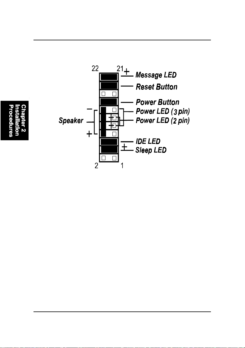
2). Front Panel Block Cable Connection

2 - 5
Installation Procedures
1). Set System Jumpers
Jumpers are used to select the operation modes for your system. Some jump-
ers on the board have three metal pins with each pin representing a different
function. A “1” is written besides pin 1 on jumpers with three pins. To set a
jumper, a black cap containing metal contacts is placed over the jumper pin/s
according to the required configuration. A jumper is said to be shorted when
the black cap has been placed on one or two of its pins. The types of jumpers
used in this manual are shown below:
NOTE: Users are not encouraged to change the jumper settings
not listed in this manual. Changing the jumper settings improperly
may adversely affect system performance.

2 - 6
AZ11MainboardManual
Clear CMOS: CLR_CMOS
The CMOS RAM is powered by the onboard button cell battery. To clear the
RTC data: (1). Turn off your computer, (2). Move the jumper to CLEAR, (3).
Move the jumper back to NORMAL, (4). Turn on your computer, (5). Hold
down the <Delete> key during bootup and enter BIOS Setup to re-enter user
preferences.
Enabling Over Voltage Driving : Magic Tunner
The 3-pin jumper allows you to start the over voltage driving capability of this
mainboard to approach the best performance.
WARNING: Voltage and frequency above CPU’s original specifica-
tions are not guaranteed to be stable.
Table of contents
Other FIC Motherboard manuals


Popular Motherboard manuals by other brands


Linear Technology
Linear Technology DC1362A-A Demo Manual

Linear Technology
Linear Technology DC2491A Demo Manual

Linear Technology
Linear Technology DC2117A Demo Manual

Shuttle
Shuttle Spacewalker AB30 user manual

Linear Technology
Linear Technology DC2166A Demo Manual

Analog Devices
Analog Devices Linear Technology DC2737A Demo Manual