Fidelis FDH-3000 User manual

www.fidelissecurity.com
QUICK START GUIDE
Fidelis Deception®
Decoy Server
Appliance

QUICK START GUIDE
Fidelis Deception®Decoy Server Appliance
www.fidelissecurity.com ©Fidelis Cybersecurity
2
1. System Overview
Fidelis Deception appliance runs emulated and RealOS decoys. It connects to Trunk port and/or
multiple flat networks and communicate with assets on the networks.
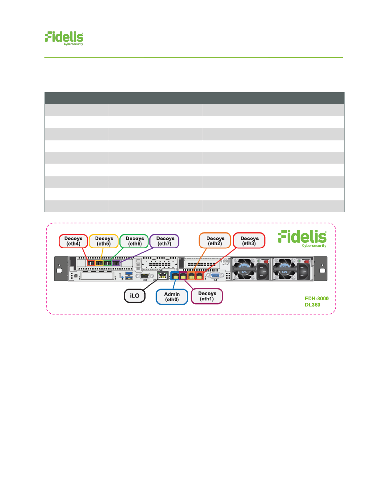
Figure 1: Fidelis Decoy Server – Appliance (1U) Rev-J
Fidelis Decoy Server reports deception alerts for all accesses to the decoys to your on-premises
Fidelis CommandPost appliance or to a remote CommandPost. Your configuration will depend on
which environment you are working with.
2. Documentation & References
Fidelis Network and Deception product documentation, appliance specifications, and instructions
can be found at https://support.fidelissecurity.com or through the icon in the CommandPost user
interface.
Appliance Default Passwords
System
Account
Default Password
Appliance Console
fidelis
fidelispass
CommandPost User Interface
admin
system
iLO
administrator
(printed on label, top of server)
Technical Support
For all technical support related to this product, check with your site administrator to determine
support contract details. For support of your product, contact your reseller. If you have a direct
support contract with Fidelis Cybersecurity, contact the Fidelis Cybersecurity support team at:
• Phone: +1 301.652.7190
• Toll-free in the US: 1.800.652.4020 – Use the customer support option.
• Email: [email protected]
• Web: https://support.fidelissecurity.com
Decoy Server Setup Checklist
Check
Fidelis Decoy Server – Appliance Requirements
Appropriate rack space, power, and cooling (Appendix A)

QUICK START GUIDE
Fidelis Deception®Decoy Server Appliance
www.fidelissecurity.com ©Fidelis Cybersecurity
3
Rack tools, rails, and connectors
Keyboard and video monitor / KVM switch for temporary appliance setup
Power cables — two per appliance, appropriate for power source and region
Ethernet cables (cat5 and optical) for Admin, Monitor, and iLO ports (Section 3)
Network switches with enough physical ports (Section 4)
Optical transceivers for switches
Logical network information: IP addresses, hostnames (Section 5)
3. Sensor: Decoy Server Port and Cabling Requirements
Fidelis Decoy Servers must be connected to the various networks with appropriate cables and in
some cases, SFP+ transceivers. The tables below describe the physical connection and cable type
associated with each port on the appliance.
Decoy Server Appliances With 1GbE rj45/Copper Ports
Cable Type
Admin (eth0)
8P8C "RJ45" (copper)
Cat 5/5e/6 patch cable
Decoys (eth1)
8P8C "RJ45" (copper)
Cat 5/5e/6 patch cable
Decoys (eth2)
8P8C "RJ45" (copper)
Cat 5/5e/6 patch cable
Decoys (eth3)
8P8C "RJ45" (copper)
Cat 5/5e/6 patch cable
Decoys (eth4)
8P8C "RJ45" (copper)
Cat 5/5e/6 patch cable (optional)
Decoys (eth5)
8P8C "RJ45" (copper)
Cat 5/5e/6 patch cable (optional)
Decoys (eth6)
8P8C "RJ45" (copper)
Cat 5/5e/6 patch cable (optional)
Decoys (eth7)
8P8C "RJ45" (copper)
Cat 5/5e/6 patch cable (optional)
ILO
8P8C "RJ45" (copper)
Cat 5/5e/6 patch cable
QUICK START GUIDE
Fidelis Deception®Decoy Server Appliance
www.fidelissecurity.com ©Fidelis Cybersecurity
4
Figure 2: Rear Port Assignments — Decoy Server
Decoy Server With 10GbE Optical Ports
Cable Type
Admin (eth0)
8P8C "RJ45" (copper)
Cat 5/5e/6 patch cable
Decoys (eth1)
8P8C "RJ45" (copper)
Cat 5/5e/6 patch cable
Decoys (eth2)
8P8C "RJ45" (copper)
Cat 5/5e/6 patch cable
Decoys (eth3)
8P8C "RJ45" (copper)
Cat 5/5e/6 patch cable
Decoys (eth4)
LC Connector
Fiber SR Patch Cable, Multimode 850nM
Decoys (eth5)
LC Connector
Fiber SR Patch Cable, Multimode 850nM
Decoys (eth6)
LC Connector
Fiber SR Patch Cable, Multimode 850nM
Decoys (eth7)
LC Connector
Fiber SR Patch Cable, Multimode 850nM
ILO
8P8C "RJ45" (copper)
Cat 5/5e/6 patch cable
Figure 3: Rear Port Assignments — Decoy Server With 10GbE Optical Ports
QUICK START GUIDE
Fidelis Deception®Decoy Server Appliance
www.fidelissecurity.com ©Fidelis Cybersecurity
5
4. Decoy Server Networking Environment
Decoy Server appliances may connect to multiple networks to deploy different decoy services.
Decoys can operate whether ports are connected to trunk ports enabling to communicate on multiple
subnets from the same port on the appliance, and/or to connect ports directly to specific subnets.
Use the tables below to identify how many and what type of network switch ports you will need for
your deployment.
Admin Network
The Admin Network connects Fidelis Decoy Server to the CommandPost and optionally to the
Sandbox. You need one switch port per Sensor appliance for the Admin network.
Appliance
Switch Port Type
Qty.
Decoy Server
8P8C "RJ45" (copper)
1
Decoy ETH1, Decoy ETH2, Decoy ETH3
Ports to connect the Decoy Server appliance to subnets through network switch directly to certain
subnets and/or using trunk port.
Appliance
Switch Port Type
Qty.
Decoy Server
8P8C "RJ45" (copper)
3
Eth4/eth5/eth6/eth7 (additional ports)
Most environments using higher network throughput will be using these ports.
The Decoy Server can be connected to a trunk port and/or to certain subnets through the switch.
Appliance
Switch Port Type
Qty.
1GbE
8P8C "RJ45" (copper)
4
10-GbE
LC Connector
2
ILO Network
Optional network for remote/out-of-band server administration. You will need one additional
switchport for each ILO connection.
Appliance
Switch Port Type
Qty.
Decoy Server
8P8C "RJ45" (copper)
1
QUICK START GUIDE
Fidelis Deception®Decoy Server Appliance
www.fidelissecurity.com ©Fidelis Cybersecurity
6
5. Decoy Server — Logical Network Configuration
The Admin and ILO should be configured according to your network configuration. See the table
below as an example. The logical network configuration of the decoys is done as part of the decoys
creation process.
Network Setting
Assignments
Interface
Admin
ILO
Hostname (FQDN)
DecoyServer1.myorg.int
Static IP Address
10.1.2.3
10.2.3.4
Subnet Mask
255.255.255.0
255.255.255.0
Gateway
10.1.2.1
10.2.3.1
Proxy Server
10.5.6.7
DNS Servers
8.8.4.4, 8.8.8.8
NTP Servers
0.pool1.ntp.org
Time Zone
UTC (+0)
6. Appliance Installation
Rack Installation
Install each appliance in an enclosure/location that has necessary power and cooling. Ensure that
the installation environment is within the operating temperature of the appliance.
Refer to Appendix A for appliance operating temperature requirements.
Power
Connect power cables to the power supplies in the back of the appliance.
See Appendix A for appliance power specifications.
Network Cabling
Using the connectors and cables described in sections 3 and 4, begin to connect the appliances to
the networks. Cable the Sensor appliances to the switches:
1. Connect Admin (eth0) port to the ADMIN switch port.
2. Connect the iLO port to the ADMIN (or ILO) switch port (optional).
7. Deception Appliance Configuration
1. Power on the Appliance(s).
2. Connect to the component’s CLI
Via KVM Console or directly Connect a keyboard
and monitor to the appliance.

QUICK START GUIDE
Fidelis Deception®Decoy Server Appliance
www.fidelissecurity.com ©Fidelis Cybersecurity
7
For Fidelis Decoy Server appliance version 9.4
or later, the screen on the right is displayed:
3. If you see the screen above, perform the following steps to apply the software. Otherwise skip to step 4.
a. Click Enter.
b. Click enter again when you see the next screen to
confirm the install; the software will be applied
and the appliance is rebooting.
4. Login in to the system through console or ILO.
5. Use these credentials at the login prompt:
user: fidelis
default password: fidelispass
you will be required to change the password, pay attention to enter the default
current (initial) password:
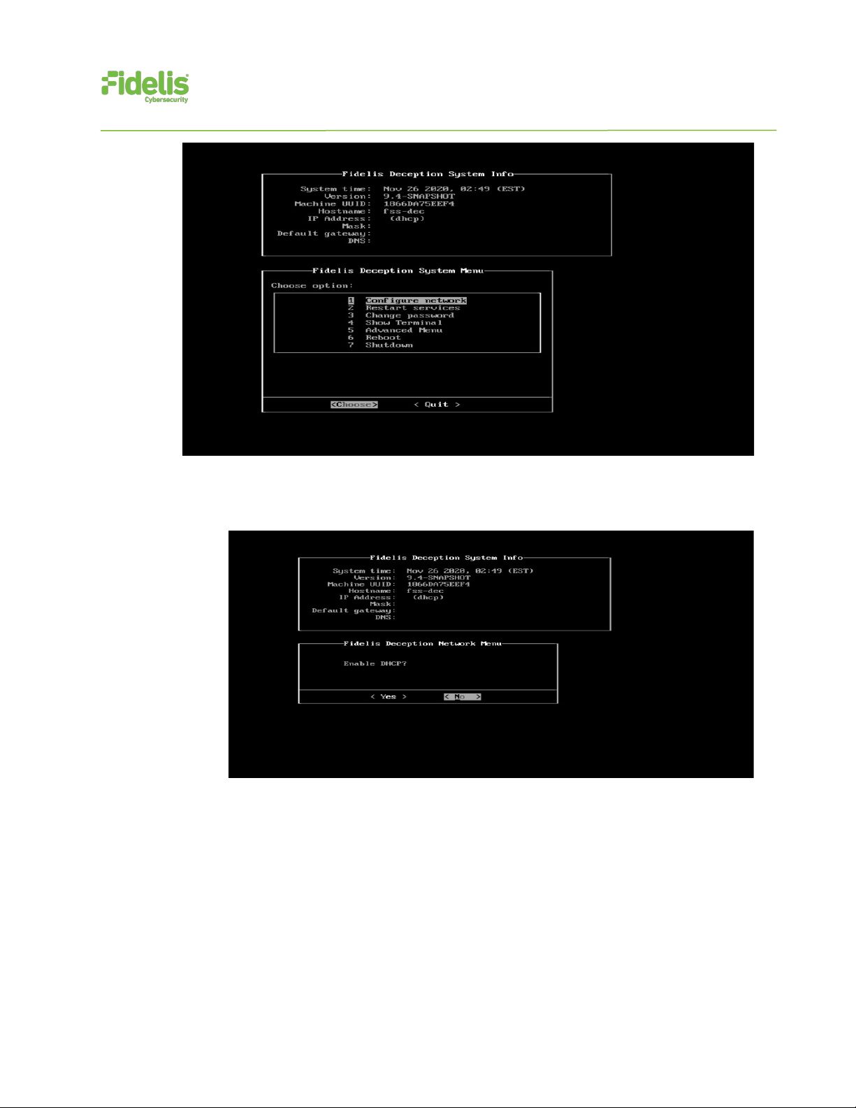
6. Within Setup, select configure network.
QUICK START GUIDE
Fidelis Deception®Decoy Server Appliance
www.fidelissecurity.com ©Fidelis Cybersecurity
8
7. Skip the DHCP configuration by selecting no; it is recommended to use a static IP address
for the interface – otherwise the Connection to the CP/management might be lost.
8. Configure the network parameters for the system management interface.

QUICK START GUIDE
Fidelis Deception®Decoy Server Appliance
www.fidelissecurity.com ©Fidelis Cybersecurity
9
9. When complete, select apply and wait for confirmation to exit Setup.
To exit choose “quit” to finish setup.

QUICK START GUIDE
Fidelis Deception®Decoy Server Appliance
www.fidelissecurity.com ©Fidelis Cybersecurity
10
8. Fidelis Decoy Server Integration — On Premises
CommandPost Environments
Register Decoy Server Appliances with Your Fidelis Enterprise CommandPost
1. Log into the CommandPost user interface from a web browser.
2. Navigate to the Administration > Components page.
3. Click Add Component Sensor.
4. Fill in the Add New Component form:
Component Type – Decoy Server
Component Name — this is a user-friendly name for the Decoy Server, not the FQDN of the
Sensor.
Component IP address — the IP address of the ADMIN interface of the Decoy Server
appliance
Description — (optional) Specify a description, for example location, business unit, etc.
5. Click Save.
6. Click Register and accept the End User License Agreement (EULA). CommandPost will
then communicate with the Decoy Server at the specified IP address.

QUICK START GUIDE
Fidelis Deception®Decoy Server Appliance
www.fidelissecurity.com ©Fidelis Cybersecurity
11
Appendix A: System Specifications
Decoy Server 3000 & 1000
FDH-3000
FDH-1000
Form Factor
1U HPE ProLiant DL360 Gen10 Chassis
1U HPE ProLiant DL360 Gen10 Chassis
CPU
Dual Gold 6234
8/16 -core 3.3Ghz
Dual Silver 4214
12/24-core 2.2Ghz
Memory
128GB
ECC DDR4 2933Mhz
64GB
ECC DDR4 2933Mhz
Storage Capacity &
Configuration
600 GB (3 TB Effective)
6x HDD, RAID-5
300 GB
2x HDD RAID-1
Network Adapters
4x 1GbE
2x 10GbE optical
4x 1GbE
2x 10GbE Optical
Out of Band Management
3 Year ILO- HPE Advanced 24x7 Tech
Support and Updates
3 Year ILO- HPE Advanced 24x7 Tech
Support and Updates
Dimensions
H: 4.29 cm ( 1.69 in)
W: 43.46 cm (17.11 in)
D: 70.7 cm (27.83 in)
H: 4.29 cm ( 1.69 in)
W: 43.46 cm (17.11 in)
D: 70.7 cm (27.83 in)
Weight (appx.)
16.27 kg (35.86 lb)
16.27 kg (35.86 lb)
Power Supply
Dual hot-swap 500W High Efficiency AC
power supplies
Dual hot-swap 800W High Efficiency AC
power supplies
Operating Temperature
10° to 35°C (50° to 95°F)
at sea level
10° to 35°C (50° to 95°F)
at sea level
AC input Requirements
100 - 120 VAC
200 - 240 VAC
100 - 120 VAC
200 - 240 VAC
BTU Rating (max)
1902 BTU/hr (100 VAC)
1840 BTU/hr (200 VAC)
1832 BTU/hr (240 VAC)
3067 BTU/hr (100 VAC)
2958 BTU/hr (200 VAC)
2949 BTU/hr (240 VAC)
This manual suits for next models
1
Table of contents
Other Fidelis Network Hardware manuals

Fidelis
Fidelis Collector Controller 10G User manual

Fidelis
Fidelis CommandPost+ User manual

Fidelis
Fidelis Deception Decoy Server FDH-1000-C User manual

Fidelis
Fidelis Network Collector SA User manual

Fidelis
Fidelis Common Criteria User manual

Fidelis
Fidelis Network CommandPost User manual

Fidelis
Fidelis Network Collector SA Rev-1 Series User manual


