Fike 10-2539 Owner's manual

Manual P/N 06-358
Rev. No: 0, 06/05
Status Indication & Monitoring (SIM) System
Control Module (CM)
10-2539
Installation and Operation
Instructions


FIKE EUROPE
Fike SIM SystemCM Page i
P/N 06-358 06/05
Introduction
Fike is pleased to present an Installation,
Operation and Maintenance Manual for our new
Status Indication & Monitoring (SIM) System.
The Fike SIM consists of a modular system
designed to aid in the supervision and
processing of signaling device status for process
industry. This document has been created to
incorporate the most up-to-date information
available for this exclusive Fike product and to
make it easy to use.
Who should read this manual?
This manual is intended for those individuals
who are custodians of the Fike SIM System.
Others such as architects, engineers, sales and
marketing personnel, etc. will find the
information useful as well.
Warranty Information
Fike provides a one-year limited manufacturer’s
warranty on the product identified in this manual.
Copies of the warranty can be obtained from an
authorized Fike sales outlet. An authorized Fike
sales outlet, using the MRA procedure, must
return warranty items. See Section 9 of this
manual for details of returning product to Fike.
Limitation of Liability
Fike Corporation cannot be held liable for any
damages resulting from the use or misuse of this
product.
Copyright, Trademark and Licensing
Notice
All Fike documentation and hardware are
copyright with all rights reserved. No part of this
product may be copied, reproduced or
transmitted by any mechanical, photographic,
electronic or other method without Fike’s prior
written consent. Fike product names are
trademarked; other product names, as
applicable, are trademarks of their respective
holders.
Disclaimer
The information contained in this manual is as
accurate as possible. This manual is intended to
be an aid to Fike authorized sales outlets or
engineers charged with the installation and
maintenance of the Fike Status Indication
Monitor. Fike does not warrant that this manual
is technically correct, complete or the product
referenced herein is free from minor flaws. Fike
reserves the right to change the information
contained in this manual without notice.
Quality Notice
Fike Corporation has maintained ISO 9001
certification since 1996. Prior to shipment, we
thoroughly test our products and review our
documentation to assure the highest quality in
all respects. In a spirit of continuous
improvement, Fike welcomes your suggestions.
Please direct all suggestions or comments to
Fike Blue Springs Product Support
Phone: +1-816-229-3405
Fax: +1-816-229-0314
or
Fike Europe Product Support
Phone: +32-14-21-00-31
Fax: +32-14-21-07-43
Any suggestions or comments become the
property of Fike Corporation.

FIKE CORPORATION
Page ii Fike SIM SystemCM
06/05 P/N 06-358
This page intentionally left blank.

FIKE CORPORATION
Fike SIM SystemCM Page iii
P/N 06-358 06/05
Table of Contents
1.0 Terms and Symbols Used In This Manual .............................................................................................1
2.0 Status Indication & Monitoring System Overview ................................................................................2
3.0 System Components................................................................................................................................3
4.0 Installation.................................................................................................................................................4
4.1 Installation Overview...............................................................................................................................4
4.2 Control Module........................................................................................................................................5
4.3 Circuit Connections.................................................................................................................................6
4.3.1 Power Input (P3)..............................................................................................................................6
4.3.2 Interlock Relay (P4) .........................................................................................................................6
4.3.3 Remote Bus (P1) .............................................................................................................................7
5.0 Operation...................................................................................................................................................9
5.1 Communication.......................................................................................................................................9
5.1.1 Field Bus..........................................................................................................................................9
5.1.2 Remote Bus.....................................................................................................................................9
5.1.3 Computer Connection......................................................................................................................9
5.1.4 Address DIP switch..........................................................................................................................9
5.2 CM Status .............................................................................................................................................10
5.2.1 Normal State..................................................................................................................................10
5.2.2 Trouble State .................................................................................................................................10
5.2.3 Alarm State....................................................................................................................................10
5.3 LED Display ..........................................................................................................................................11
5.4 Operating Modes ..................................................................................................................................11
5.4.1 Navigation......................................................................................................................................11
5.4.2 Main Menu.....................................................................................................................................12
5.4.3 Home Operation ............................................................................................................................12
5.4.4 Alarm List Operation......................................................................................................................13
5.4.5 Error List Operation .......................................................................................................................14
5.4.6 Found List Operation .....................................................................................................................15
5.4.7 Program FM Counter Operation....................................................................................................16
5.4.8 Current FM Reading Operation .....................................................................................................17
6.0 Device configuration..............................................................................................................................18
6.0.1 ID Number (“I”)..............................................................................................................................18
6.0.2 Operation Mode (“S”)....................................................................................................................18
6.0.3 Store configuration in field module................................................................................................18
7.0 Decommissioning Procedure / Check-List ..........................................................................................19
8.0 Spare Parts..............................................................................................................................................20
9.0 Specifications .........................................................................................................................................21
10.0 Repair and Return Authorization..........................................................................................................22
Annex A CONTROL Module Menu..................................................................................................................23

FIKE CORPORATION
Page iv Fike SIM SystemCM
06/05 P/N 06-358
List of Exhibits
Exhibit 2-1 SIM System Block Diagram............................................................................................................... 2
Exhibit 3-1 FM Photo........................................................................................................................................... 3
Exhibit 3-2 CM Photo........................................................................................................................................... 3
Exhibit 4-1 CM Block Diagram............................................................................................................................. 5
Exhibit 4-2 CM Bottom View Wiring Connections ............................................................................................... 6
Exhibit 4-3 CM Power Input Wiring...................................................................................................................... 6
Exhibit 4-4 Interlock Relay.................................................................................................................................. 6
Exhibit 4-5 CM Top View –P1-P2 Wiring Connections....................................................................................... 7
Exhibit 4-6 Remote Bus Wiring Diagram............................................................................................................. 7
Exhibit 4-7 Status Wiring Diagram....................................................................................................................... 8
Exhibit 5-1 Field Bus............................................................................................................................................ 9
Exhibit 5-2 Remote Bus....................................................................................................................................... 9
Exhibit 5-3 Serial Port.......................................................................................................................................... 9
Exhibit 5-4 Address DIP Switch........................................................................................................................... 9
Exhibit 5-5 Power LED ...................................................................................................................................... 10
Exhibit 5-6 Trouble LED .................................................................................................................................... 10
Exhibit 5-7 Alarm LED ....................................................................................................................................... 10
Exhibit 5-8 Control Module Pushbuttons...........................................................................................................11
Exhibit 5-9 Control Module Digits ...................................................................................................................... 11
Exhibit 5-10 Control Module Main Menu Table ................................................................................................. 12
Exhibit 5-11 Home Menu Counter Identifier Table ............................................................................................ 12
Exhibit 5-12 Alarm List Top of File Indicator...................................................................................................... 13
Exhibit 5-13 Alarm List Bottom of File Indicator ................................................................................................13
Exhibit 5-14 Alarm List Menu Navigation .......................................................................................................... 13
Exhibit 5-15 Error List Top of File Indicator.......................................................................................................14
Exhibit 5-16 Error List Bottom of File Indicator..................................................................................................14
Exhibit 5-17 Error List Menu Navigation............................................................................................................ 14
Exhibit 5-18 Found List Top of File Indicator..................................................................................................... 15
Exhibit 5-19 Found List Bottom of File Indicator................................................................................................ 15
Exhibit 5-20 Found List Menu Navigation.......................................................................................................... 15
Exhibit 5-21 Program FM Counter Menu Navigation......................................................................................... 16
Exhibit 5-22 Current FM Reading Lookup Table............................................................................................... 17
Exhibit 6-1 Decommissioning Steps..................................................................................................................19
Exhibit 8-1 Spare Parts List............................................................................................................................... 20
FIKE CORPORATION
Fike SIM SystemCM Page 1 of 24
P/N 06-358 06/05
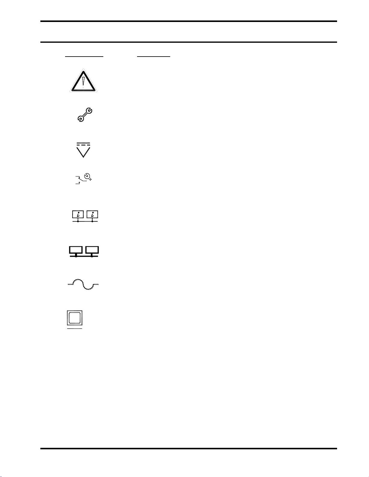
1.0 TERMS AND SYMBOLS USED IN THIS MANUAL
Term/Symbol
Description
Alarm symbol. This symbol is on the face of the Control Module (CM) next
to the red alarm LED. This LED will illuminate when the CM has validated
an alarm signal from any field module. The alarm occurs when an input
circuit at the field module has been activated.
Trouble symbol. This symbol is on the face of the CM next to the yellow
trouble LED. This LED will illuminate on any trouble condition resulting
from either the CM itself or any indicating fault from a connected field
module.
DC Power symbol. This symbol is on the face of the CM next to the green
LED. This LED illuminates at a normal state to indicate that the unit is
receiving power. This symbol is also located on the bottom of the CM. It
designates the 24VDC input wiring location.
NO NC C
Trouble Relay symbol. This symbol located on the bottom of the CM. It
designates the relay output wiring connections.
Remote Bus symbol. This circuit is a network connection that sends status
information from the Control Modules to a computer for system monitoring.
This network is provided to support future upgrades to the SIM system –
features associated with this network are currently not implemented.
Field Bus symbol. This circuit is a network connection that reads status
information from field modules. Up to 32 field modules can be monitored.
Fuse symbol. This designation represents a circuit protection fuse. The
fuse is rated at the amperage noted next to this marking.
DB9
Computer Connection symbol. This designation represents the location
for the computer connection. Using a straight-through serial cable, the CM
can be connected from this DB9 connection to a computer serial port. This
connection is provided to support future upgrades to the SIM system –
features associated with this network are currently not implemented.
Symbol for “ohm”. Unit of resistance.
FIKE CORPORATION
Page 2 of 24 Fike SIM SystemCM
06/05 P/N 06-358
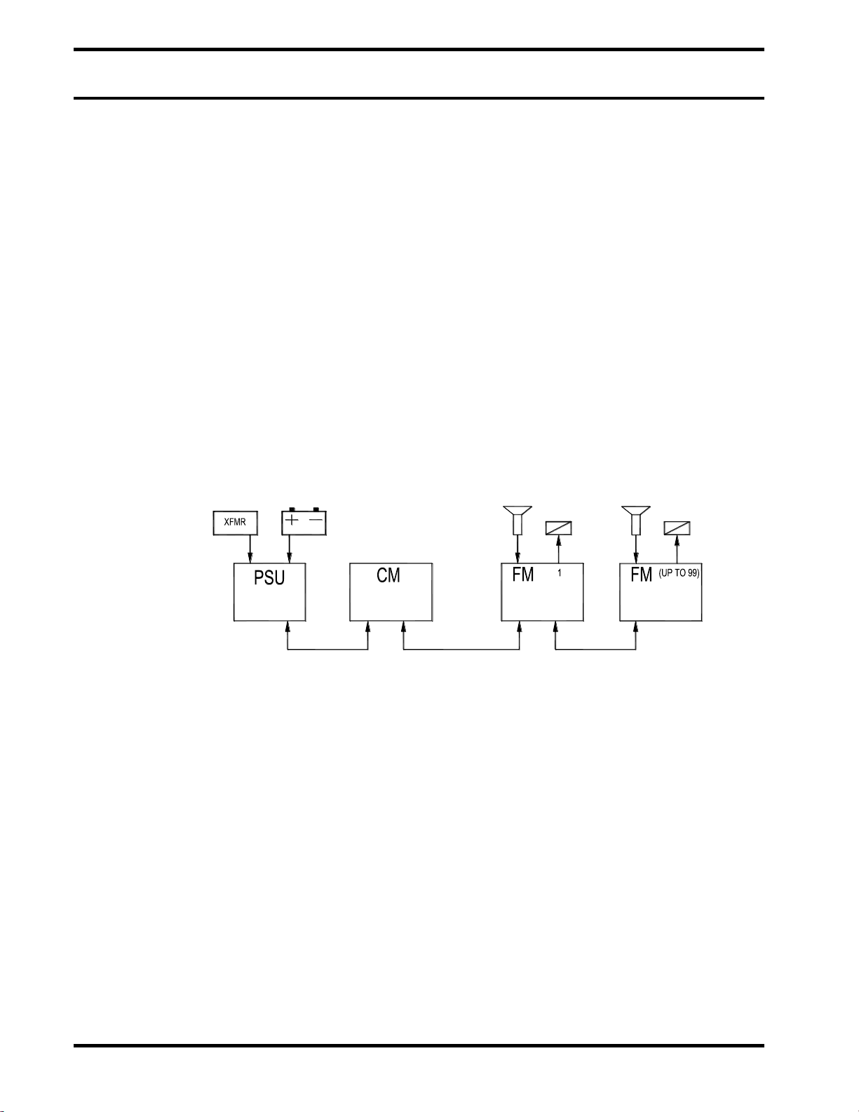
2.0 STATUS INDICATION & MONITORING SYSTEM OVERVIEW
The SIMSystem is a modular contact
monitoring system combining the latest in
addressable technology with simplicity of
installation and maintenance. All system
modules are DIN rail mounted to allow for a
variety of installation options.
A bus type communication circuit ties the
various field modules into one easy to operate
supervision system. On the Control Module
(CM) the customer has the ability to step through
a menu format to retrieve detailed status
information off all connected field modules. The
menus can be operated easily by process
operators.
This manual will provide the necessary
information to properly install and monitor the
Control Module (CM) for the SIMSystem.
POWER
SUPPLY
UNIT
CONTROL
MODULE
SENTINEL
FIELD
MODULE
SENTINEL
FIELD
MODULE
Exhibit 2-1 SIM System Block Diagram
FIKE CORPORATION
Fike SIM SystemCM Page 3 of 24
P/N 06-358 06/05
3.0 SYSTEM COMPONENTS
The cornerstone of the system is the Field
Module (FM). Four colored LED’s provide instant
visual indication of module status. The DIN rail
mounting allows for flexibility when choosing an
enclosure. The FM is a component that allows
mounting in close proximity to the supervised
contact device outside the hazardous
environment, thereby minimizing field wiring.
Shorter wire runs greatly reduce the interference
from electrical and radio frequency sources,
allowing for a much more reliable monitoring
system. The FM’s detection inputs are
intrinsically safe barrier type detection inputs
used to monitor any contact closure sensor. The
input type can be programmed to facilitate both
normally closed (NC) and normally open (NO)
contacts. Depending on the wiring style, full
wiring supervision can be chosen in order to
differentiate wiring troubles from switch closure
activated states. The FM is powered by a simple
24VDC power supply and provides a network
connection to distribute its module status for
supervision by the Control Module (CM). An
onboard form “C” relay enable equipment
shutdowns and remote notification of system
trouble and alarm conditions.
Exhibit 3-1 FM Photo
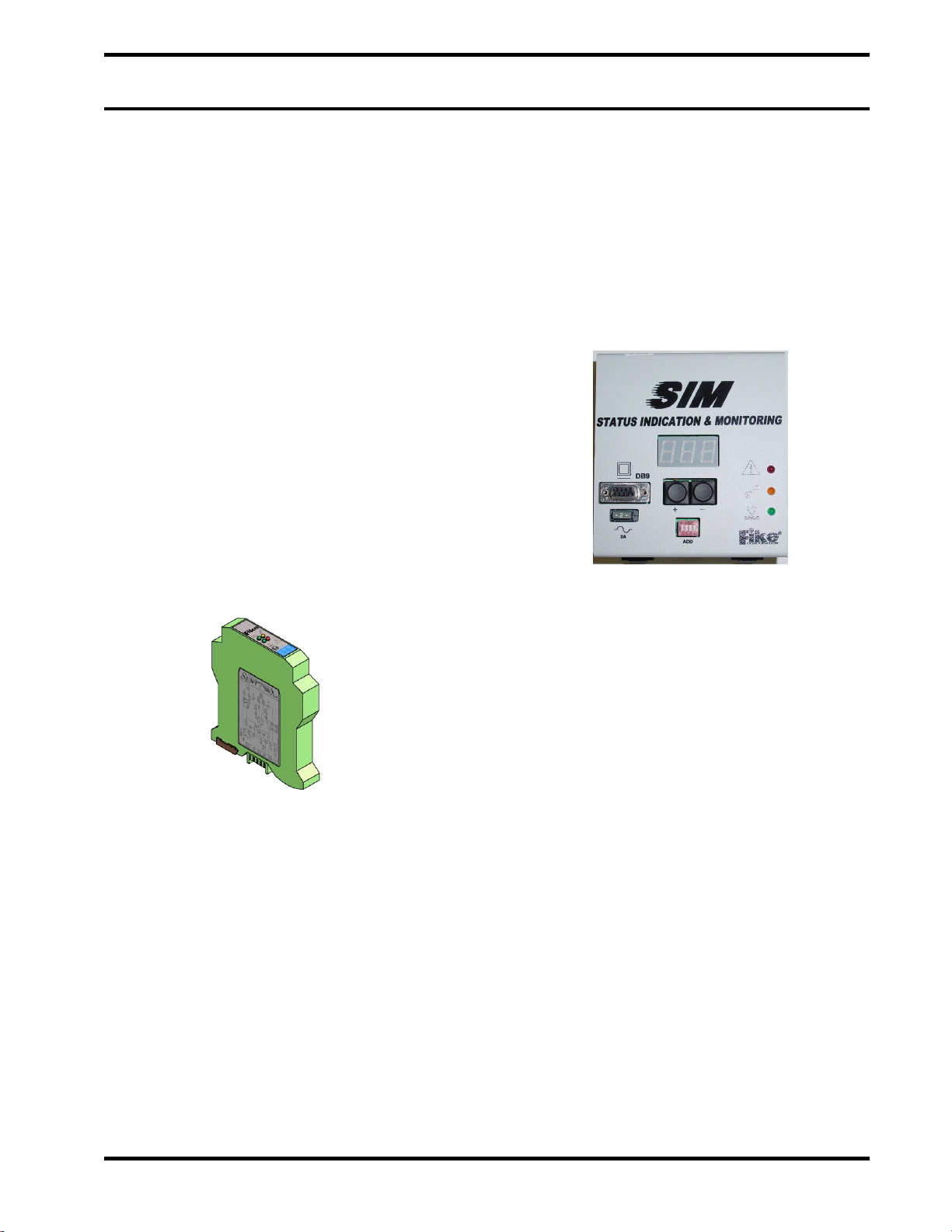
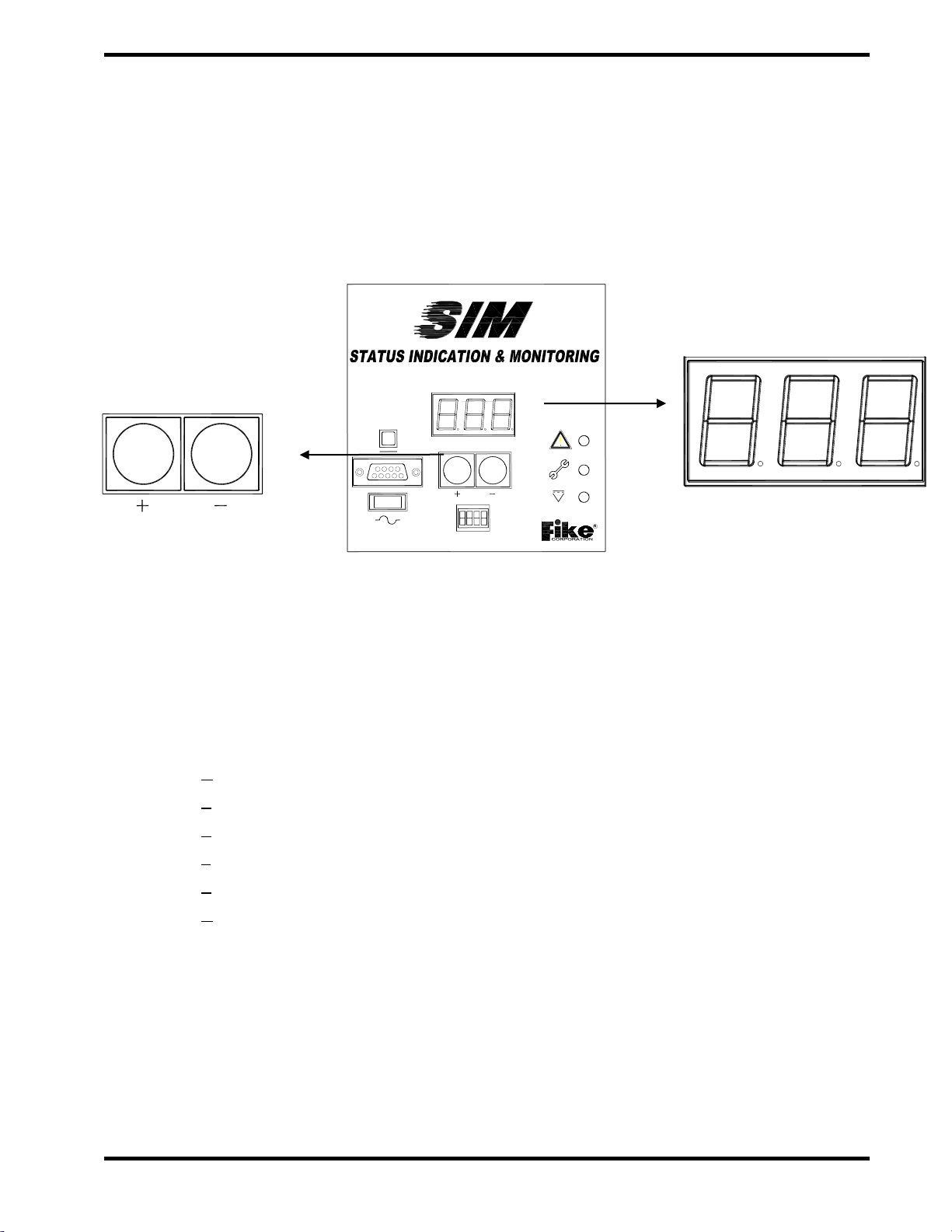
The Control Module (CM) provides a central
communication point for diagnostics. This
module will typically be installed in an area
removed from the process environment such as
a control room. The CM has two push buttons to
access the various menus and three LEDs for
identification of the system status within the
menus. The Control Module (CM) provides the
user with a form “C” relay for equipment
shutdowns and remote notification of system
trouble and alarm conditions.
Exhibit 3-2 CM Photo

FIKE CORPORATION
Page 4 of 24 Fike SIM SystemCM
06/05 P/N 06-358
4.0 INSTALLATION
4.1 INSTALLATION OVERVIEW
The effectiveness of a control and detection
system, such as contact monitoring and
industrial supervision, depends upon the
correctness of the initial measurement of the
sensor device.
It is therefore, critical that all possible measures
are taken to reduce the individual system
components’ electrical disturbances to an
absolute minimum.
A supervision system basically consists of three
components: One or more sensor devices, an
electronic field module reading the sensor status
and one overall supervising control device.
Instrumentation wiring interconnects these
components.
The field module is microprocessor-based and
shall be installed in a location that maintains a
temperature rating of -10°C to 50°C (15°F to
125°F) when it is installed in an auxiliary
housing.
Electronic devices, microprocessors and field
wiring are influenced by the electromagnetic
“environment” surrounding these components.
The use of cellular telephones, transmitters,
induction motors, welding equipment or the
presence of power cables and transformers can
create environments with high levels of
electromagnetic radiation, resulting in induced
electrical “noise” or voltage peaks.
Such effects are known to designers and
manufacturers of instrumentation and control
systems (PLC’s), used in industrial
environments and are handled through the use
of specially designed electronic filters. These
filters neutralize the unwanted noise and offer a
“clean” signal for further processing.
It is essential to practice extreme caution when
selecting component location, cable
specifications, cable routes, and the
“cleanliness” of the offered power source. In
order to reduce the electromagnetic induced
noise to a level that will not affect the required
performance of the supervision control system,
verify all earth connections. It is preferred to
have the enclosure and conduits connected to
Protective Earth (similar with other building
grounds) while the drain wires from the field
wiring and each module ground connected to a
separate Instrument Earth. This Instrument
Earth connection shall not have inductive or
capacitive loading such as motors, welders, or
other industrial equipment. Where a separate
earth connection is not available, the drain wires
and module ground connections should be
made to the DC supply common. Complying
with the following recommendations will help
minimize the induced noise to acceptable levels.

FIKE CORPORATION
Fike SIM SystemCM Page 5 of 24
P/N 06-358 06/05
4.2 CONTROL MODULE
The Control Module (CM) is the overall status indication point for the SIM control system. It provides a
single point for retrieving system status as for troubleshooting all SIM modules attached to the Field Bus.
Exhibit 4-1 CM Block Diagram

FIKE CORPORATION
Page 6 of 24 Fike SIM SystemCM
06/05 P/N 06-358
Exhibit 4-2 CM Bottom View Wiring Connections
4.3 CIRCUIT CONNECTIONS
4.3.1 Power Input (P3)
Power Input requires between 18 to 30 Vdc, at
500mA. For the Control Module, power needs to
be uninterruptible for continuous operation of the
Field Bus.
4.3.2 Interlock Relay (P4)
The interlock relay is available to provide FM
status to monitoring equipment. The relay is a
“fail-safe” relay that will transfer upon any system
trouble or alarm condition. This can be used
for equipment shutdown, visual, audible, or other
type annunciation. Trouble conditions must be
acknowledged and identified prior to continuing
to run the process.
Note: The relay designations (NO, NC, and C)
are shown in the de-energized state with no
power applied. When the CM is powered and
the module has no trouble or alarm, the
interlock relay is energized.
Exhibit 4-3 CM Power Input Wiring
Exhibit 4-4 Interlock Relay
24VDC
P3 P4
NONC C
PN 90700096-S
[ insulate ]
24VDC
CONTROL MODULE (P3)
-
+
Shield
No termination
Twisted Pair
of Drain Wire
No
Connection
24VDC
Process Monitoring
NO
C
NC Equipment (*See Note*)
FIKE CORPORATION
Fike SIM SystemCM Page 7 of 24
P/N 06-358 06/05
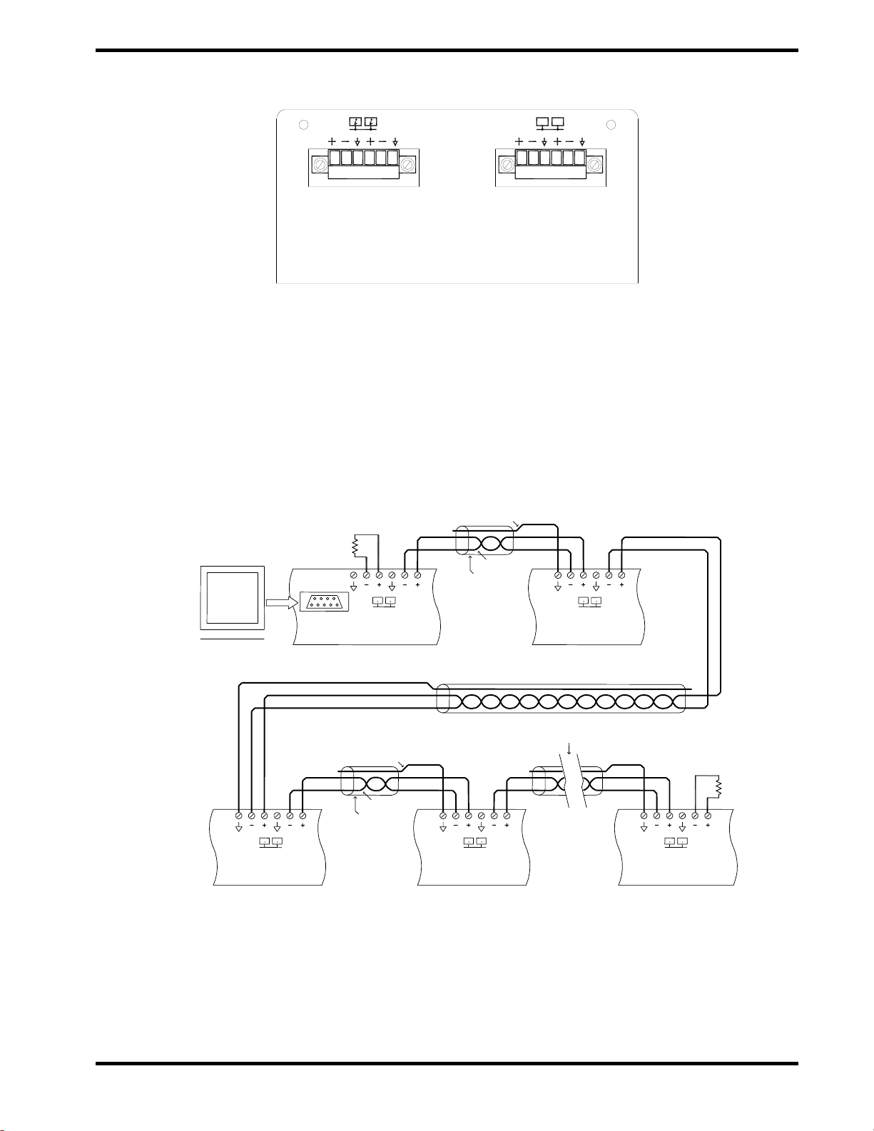
Exhibit 4-5 CM Top View –P1-P2 Wiring Connections
4.3.3 Remote Bus (P1)
The hardware for the remote bus is provided for
future planned upgrades to the SIM system.
Once these upgrades are implemented, a PC will
be capable of monitoring each of the control
loops via the attached Control Modules. Refer to
Exhibit 4-6 for the wiring diagram of the Remote
Bus.
Exhibit 4-6 Remote Bus Wiring Diagram
i
i
P1
i
i
A
A
i
i
B
i
B
A
P1
i
Shield
i
P1
PC
B
Twisted Pair
Shield Wire
B
A
Shield
A
P1
i
B
Shield Wire
Additional AMs
Twisted Pair
P1
Control
Module (CM) 1
Control
Module #3
Control
Module #4
SIM System - Remote Bus (future state)
Control
Module #2
Last Control
Module (up to 16)
140 Ohm
140 Ohm
P1 P2
BA

FIKE CORPORATION
Page 8 of 24 Fike SIM SystemCM
06/05 P/N 06-358
4.3.4 Field Bus Connection (P2)
The Field Bus is an RS485 network running a
proprietary protocol that transmits control
information between the Field Module (FM) and
Control Module (CM). Belden 9841 or RE-Y2Y
cabling is recommended for this circuit.
Maximum resistance R=50 Ω, inductance
L=100uH, and capacitance C=0.02uF with a
maximum length of 300m (1,000 ft).
The menu structure for the field bus connections
allows for identification of 99 field devices,
however only 32 can be physically connected
onto a single field bus network.
Note: The B+ of the CM connects to the FM –
(17), similarly the B- of the CM connects to
the FM + (16). Install the 140 Ω, 1/2 watt
resistor at each end as shown.
Note: The drain wire should only be
connected on one end of each wire run.
Make sure that the drain wire, which is not
connected to a terminal, is cut and insulated
from making contact to metal or other wiring
connections.
Additional RC8
Twisted Pair
Shield Wire
-
+-+
Relay Module
BA
(RC8) #1
P1 Shield -
+-+BA
RC8 #2
P1 -
+-+
Last RC8(Up to 4)
BA
P1
140 ohm
of Drain Wire [ insulate ]
-
+-+
-
+ + -
Twisted Pair
Shield Wire
Controller (EPC) #1
Explosion Protection
-+ +
-BA
P1 Shield
Annunciator
Module (AM)
BA
++
- -BA
P1
EPC #2 Last EPC (Up to 4)
B
-+-
P1
A+
Additional EPC
Unit (PSU)
Power Supply
BA
No termination
Shield Wire
Twisted Pair
140 ohm
P2 Shield P1
Exhibit 4-7 Status Wiring Diagram

FIKE CORPORATION
Fike SIM SystemCM Page 9 of 24
P/N 06-358 06/05
5.0 OPERATION
5.1 COMMUNICATION
5.1.1 Field Bus
The Field Bus ties all the Field Modules together
to form a network for reporting of system status
to the Control Module. (up to 32 FM’s can be
connected).
Exhibit 5-1 Field Bus
5.1.2 Remote Bus
The Remote Bus interconnects all of the Control
Modules for central annunciation of all control
loops at a permanently attached computer.
When utilizing multiple Control Modules each of
the modules require addressing via the 4 ADD
DIP switches depicted below. The Address
switch is not applicable when there is only a
single CM in the SIM System Remote Bus.
Exhibit 5-2 Remote Bus
Exhibit 5-3 Serial Port
5.1.3 Computer Connection
The CM is a programmable module for system
configuration and monitoring by way of a DB9
serial port connection to a PC using Software.
This connection is provided to support future
upgrades to the SIM system –features
associated with this network are currently not
implemented.
5.1.4 Address DIP switch
The ADD switch located on the front of the
module provides the ability to address the CM
when using multiple SIM Remote Bus
connections. Each CM on the Remote Bus shall
be identified with a different address.
.
Exhibit 5-4 Address DIP
Switch
DB9
2A
2
ADD
DB9
24VDC
ADD

FIKE CORPORATION
Page 10 of 24 Fike SIM SystemCM
06/05 P/N 06-358
5.2 CM STATUS
The CM is the customer interface for the SIM
system. The following tasks are accomplished
by the CM:
Monitors all Field Modules connected to the
Field Bus and displays general status.
Provides a central location for quick overview
of devices found and counters on devices in
trouble or alarm.
Provides detailed listing including device
identification for all field module states.
Provides a central location for overall status
indication via LED’s and interlock relay.
Real time troubleshooting of field modules by
direct analog readout of field sensors.
Enables the user to program the field modules
operational mode and device identification.
The SIM operation can be classified into three main states of operation: Normal, Trouble and Alarm. Each
of these states is described in sections 5.2.1 through 5.2.3.
5.2.1 Normal State
When power is applied the Control Module performs a self test and
initialization. At the end of the initialization, the local piezo beeps two
(2) times short. It can then enter the “NORMAL” state if the power is of
an appropriate voltage and there are no troubles or alarms. In the
Normal State the green Power LED is ‘ON’, the interlock relay is
energized. All other LED’s are ‘OFF’.
5.2.2 Trouble State
A trouble occurs on the SIM system if any one of the supervised field
devices experiences a wiring fault open or short condition, if the
programmed amount of FM’s connected to the CM exceeds the
amount of devices found on the Field Bus, if the CM fails to pass its
self test upon power on or if the input voltage drops below 18VDC. In
the Trouble State the yellow Trouble LED is ‘ON’, and the interlock
relay is de-energized. Depending on the cause of the trouble, the
system may or may NOT be completely functional. Each trouble
should be investigated to determine the cause and promptly fixed.
Each trouble, except for self test failure and power failure disable, will
be non latching. If the non latching trouble is resolved, the CM re-
energizes the Interlock Relay and clears the Trouble LED.
5.2.3 Alarm State
When a detection circuit of a connected FM has exceeded the alarm
conditions required by the configuration, the CM enters the Alarm
State. In the Alarm State the red Alarm LED is ‘ON’, and the Interlock
Relay is de-energized. The alarm state is non latching. If the alarm is
cleared on the FM the CM returns automatically to the Normal state.
Exhibit 5-5 Power LED
Exhibit 5-6 Trouble LED
Exhibit 5-7 Alarm LED
24VDC
Green
Yellow
Red
FIKE CORPORATION
Fike SIM SystemCM Page 11 of 24
P/N 06-358 06/05
5.3 LED DISPLAY
The Control Module is a menu driven device,
easily controlled by the two pushbutton switches
on the front of the module.
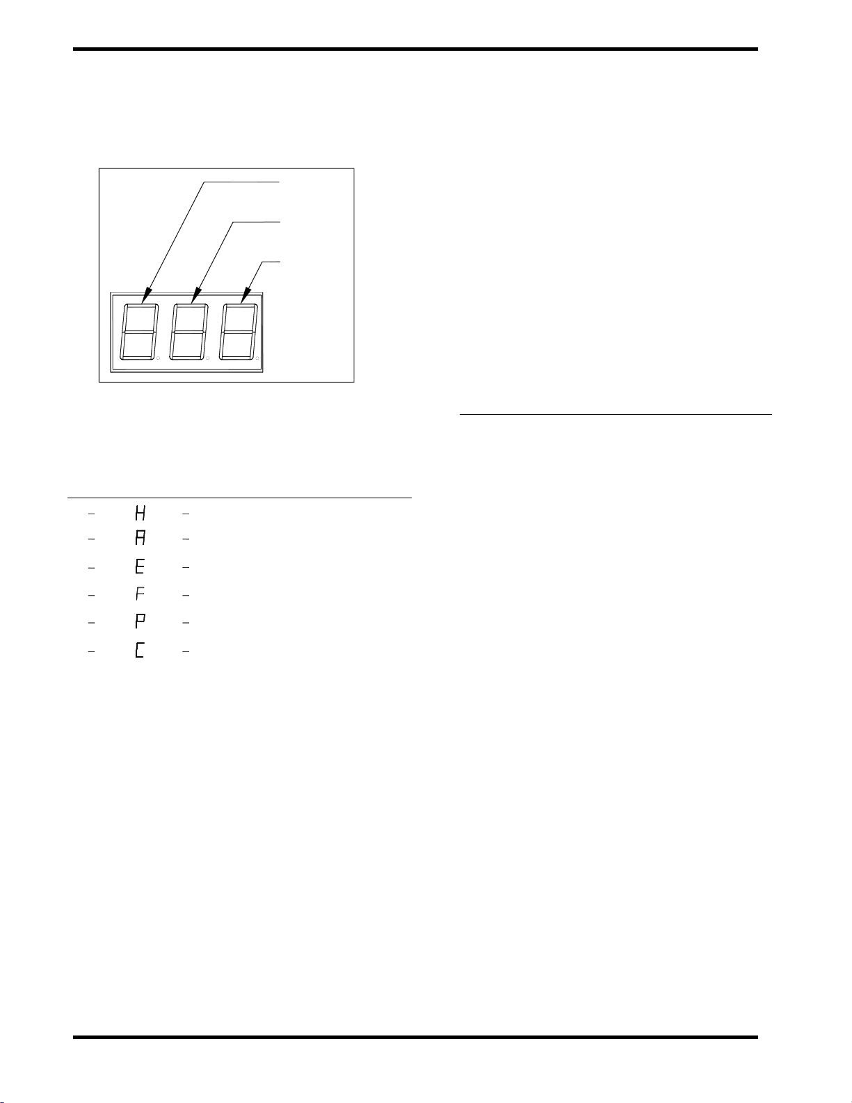
All information is depicted on the 3 character
LED display. All notations to follow will contain
specific references to Digit 1, Digit 2, and Digit 3
of this display.
Exhibit 5-8 Control
Module Pushbuttons
Exhibit 5-9 Control
Module Digits
5.4 OPERATING MODES
There are six operating modes that the Control
Module utilizes:
Home
Alarm
Error
Found
Program
Current reading
FM configuration (special mode)
After power up restart, the Control Module will
default into the Home mode.
5.4.1 Navigation
Navigation through the Control Module menus is
easily accomplished while using the following
rules:
1. Momentarily pressing both switches
simultaneously will display the current
operating mode of the Control Module.
2. Pressing and holding both switches
simultaneously for at least 5 seconds will
allow the user access to the various
operating modes (Menu Mode) of the Control
Module.
3. Once the Menu Mode of operation is
entered, the left key is used to scroll
between the menu options, and the right key
is used to select the desired option.
4. The Menu Mode will timeout after 15
seconds if no activity is present.
2A
2
ADD
DB9
24VDC
FIKE CORPORATION
Page 12 of 24 Fike SIM SystemCM
06/05 P/N 06-358
5.4.2 Main Menu
Upon entry into the Main Menu, the following
operational modes may be accessed:
Exhibit 5-10 Control Module Main Menu Table
Digit Number
1
2
3
Option Selected
HOME
ALARM LIST
ERROR LIST
FOUND LIST
PROGAM FM COUNTER
CURRENT FM READING
In order to scroll from –H- to any other option,
press the left pushbutton until the desired
operational mode is displayed, then select that
mode by pressing the right pushbutton.
5.4.3 Home Operation
The Home Menu is provided to annunciate the
current (most recent) counted Field Modules
found, in error, in alarm, and required. In order to
view a specific counter value, use the left
pushbutton to scroll up and the right pushbutton
to scroll down.
Digit 1 is used to identify the counter type (A, E,
F, or P). Digits 2 and 3 are used to indicate the
value of the selected counters. Counter values
are from 01 to 99 and are decimal represented.
Exhibit 5-11 details these counters.
Designates
Counter
Type
Designates
Counter
Value
Counter
represents
amount of FM
modules
1
2
3
A
X
X
in Alarm
E
X
X
in Trouble / Error
F
X
X
Found
P
X
X
Programmed
Exhibit 5-11 Home Menu Counter Identifier
Table
DIGIT 1
DIGIT 2
DIGIT 3
FIKE CORPORATION
Fike SIM SystemCM Page 13 of 24
P/N 06-358 06/05
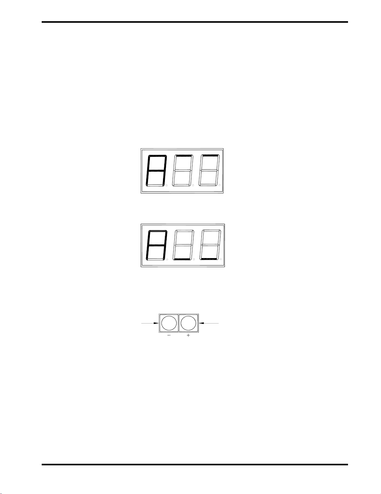
5.4.4 Alarm List Operation
The Alarm List is provided to annunciate in detail
the Field Modules that are currently in ALARM
state, by representing their unique field bus
identification number.
When a Field Module is in alarm state its
identification number will be added to the Alarm
list. All numbers appear in sequential logic order
thus not in order of when the alarm condition
was met. Digit 1 is used to identify the Alarm List
and remains “A”. Digits 2 and 3 are used to
indicate the FM’s unique device number.
It displays all FM device numbers as found to be
in alarm state with the lowest number at the top
of the list, and the highest at the bottom. The top
of the alarm list is designated with two dashed
lines at the top of the display as shown in exhibit
5-12. The bottom of the alarm list is designated
with two dashed lines at the bottom of the
display as shown in exhibit 5-13. Use the + key
to scroll forward in the list. Use the - key to scroll
backwards in the list. Press both keys at the
same time to move to the top of the list (see
exhibit 5-14).
Exhibit 5-12 Alarm List Top of File Indicator
Exhibit 5-13 Alarm List Bottom of File Indicator
Exhibit 5-14 Alarm List Menu Navigation
Example List Items:
“A01” –Field Module 01 is in alarm state.
“A72” –Field Module 72 is in alarm state.
Press to scroll forward in the list Press to scroll backward in the list
Press both keys to return to top of list

FIKE CORPORATION
Page 14 of 24 Fike SIM SystemCM
06/05 P/N 06-358
5.4.5 Error List Operation
The Error List is provided to annunciate in detail
the Field Modules that are currently in
TROUBLE/ERROR state, by representing their
unique field bus identification number.
When a Field Module is in trouble state its
identification number will be added to the Error
list. All numbers appear in sequential logic order
thus not in order of when the trouble condition
was met. Digit 1 is used to identify the Error List
and remains “E”. Digits 2 and 3 are used to
indicate the FM’s unique device number.
It displays all FM device numbers as found to be
in trouble state with the lowest number at the top
of the list, and the highest at the bottom. The top
of the error list is designated with two dashed
lines at the top of the display as shown in exhibit
5-15. The bottom of the error list is designated
with two dashed lines at the bottom of the
display as shown in exhibit 5-16. Use the + key
to scroll forward in the list. Use the - key to scroll
backwards in the list. Press both keys at the
same time to move to the top of the list (see
exhibit 5-17).
Exhibit 5-15 Error List Top of File Indicator
Exhibit 5-16 Error List Bottom of File Indicator
Exhibit 5-17 Error List Menu Navigation
Example List Items:
“E05” –Field Module 05 is in error/trouble state.
“E34” –Field Module 34 is in error/trouble state.
Press to scroll forward in the list Press to scroll backward in the list
Press both keys to return to top of list
Table of contents
Other Fike Control System manuals

Fike
Fike FIK-CZ-6 User manual

Fike
Fike CyberCat 1016 User manual

Fike
Fike CyberCat 1016 Owner's manual

Fike
Fike Cheetah Xi User manual

Fike
Fike 10-071 User manual

Fike
Fike CyberCat 50 10-070 Manual

Fike
Fike Cheetah Xi User guide

Fike
Fike Epaco User manual

Fike
Fike 55-042 User manual

Fike
Fike FIK-PULL-SA User manual

Popular Control System manuals by other brands


Deif
Deif DELOMATIC 4 Series Replacement instructions

Politec
Politec ALES QUAD Series Installation and mounting guide

WURM
WURM FRIGOLINK ANI-1F1 manual

Numatics
Numatics G2-2 Series Quick start manual

Honeywell
Honeywell Excel 800 LION Installation and commissioning instructions

Balcrank
Balcrank PGM-40 Operation, installation, maintenance and repair guide