Fike TWINFLEX SRM 100-0010 User manual

INSTALLATION AND MAINTENANCE INSTRUCTIONS
100-0010 Twinflex SRM Module
26-1369-01
1
TWINFLEX®SRM
Solenoid Releasing Module
100-0010
(Suitable for TWINFLEX®SRP control panels from V01.000)
Solenoid Releasing Module
Engineering and Commissioning
Manual
(TO BE RETAINED BY THE COMMISSIONING ENGINEER)

26-1369-01
2
Contents
General Description......................................................................................................3
Before Installation.........................................................................................................4
Positioning......................................................................................................................................4
Device Installation / Mounting ......................................................................................................4
Connections ..................................................................................................................6
Module Layout................................................................................................................................6
Zone Connections (J1)........................................................................................................7
Solenoid Connections (J2)..................................................................................................8
External Power for Solenoid (J3) ........................................................................................9
Input Connections (J4, J5, J6)..........................................................................................10
Discharge pressure circuit (J4) .........................................................................................11
Bottle pressure switch circuit (J5) .....................................................................................11
Solenoid Missing circuit (J6) .............................................................................................11
Acceptance Testing ....................................................................................................12
Hardware Connections ...............................................................................................13
Inspections & Testing.................................................................................................13
DIL Switch SW2 Settings............................................................................................14
LED Table.....................................................................................................................15
Operation.....................................................................................................................16
Technical Data.............................................................................................................17
Technical Support.......................................................................................................18

26-1369-01
3
General Description
The SRM (Solenoid Releasing Module) is a module that controls the
operation of the Solenoid valve(s) in a Suppression system. The typical
applications where the SRM can be implemented for are –Pre-action
sprinkler, Deluge, CO2, Water mist and Foam. The SRM can be used to
monitor a Discharge Pressure switch to provide feedback to the Control
Panel that the Releasing agent has been dumped into the protected space.
The SRM can also be used to monitor the Solenoid and container for any
fault conditions like low bottle pressure, wire connections, faulty actuator
coil, tamper valve etc.
The SRM is connected to the Twinflex SRP (Single Releasing Panel) via a
dedicated zone circuit.
The zone circuit is configured on the SRP as –Release SRM. A maximum of
2 SRMs can be connected on a Zone circuit. The communication between
the SRP and SRM(s) is established via the Twinflex signaling protocol.

26-1369-01
4
Before Installation
The Twinflex SRM must be installed in compliance with the SRP installation manual. The installation
must also meet the requirements of any local authority and BS7273 Pt1 : 2006.
Positioning
The module should be mounted securely and care should be taken to ensure the device is accessible for
future maintenance.
Device Installation / Mounting
All wiring must be installed in compliance with the recommendations laid out by BS7273 Pt1 : 2006
as well as any special recommendations documented in the control panel installation manual. The
cabling used should be of a 2-core 1.5mm2screened, fire resistant type (e.g. MICC or FP200 equivalent),
and is to be wired in the form of a screened 2-core radial circuit (with no spurs) from the control panel,
terminating at the last (“End of Line”) device. Note that ALL connections, including inputs, should be
made via screened FP cable.
Fix the back box in a suitable position using the screw holes provided on the back, remembering to allow
enough space for the correct termination of the appropriate fire resistant cable. See technical data on
page 15 for enclosure dimensions.
This equipment is only IP30 rated so must be mounted outside the area being protected.
There are six 20mm cable entry points provided on the top and one on each side of the enclosure.
These are not knockouts and should be removed either by running a sharp knife around their outer
groove or drilling out the cable entry points.
Site safety procedures should always be observed when using a knife to remove the cable entry points.
If cable entry points are drilled out the PCB should be removed from the enclosure before drilling
(see Figure 1).

26-1369-01
5
Figure 1 –The SRM Layout
Stuffing glands should be used on all cables to prevent stress being applied to the PCB mounted
terminals.
Care should be taken when terminating devices to ensure all cables are correctly sleeved and
connections are secure. Improper connections will prevent a system from responding correctly in the
event of a fire.
To prevent an inadvertent extinguishant discharge, the solenoid valve should not be connected to the
container while wiring the SRM circuits and setting up the DIL switches SW1 and SW2. The solenoid
should be connected to the container after all other installation has been completed and verified.

26-1369-01
6
Connections
In order to carry out high voltage testing and resistance measurements, temporarily connect the
incoming and outgoing zone cables to each other using a 3-way connector block. Once all testing has
been carried out on the cabling, and ‘continuity & integrity’ has been proven, the SRM may be
connected and assembled.
Please remember that all high voltage testing must be carried out before the installation of the SRM
otherwise the electronics will be damaged.
Remember that the device at the end of the line must have its EOL signal activated using the relevant
EOL switch (Refer to DIL switch settings table on page 12). Do not use a resistor or capacitor (or
another manufacturer’s End of Line device) as the end of line, as this may prevent correct operation of
the zone.
Module Layout
The following figure shows the SRM layout. Terminals J1 thru J6 are used for all the field wiring
connections. DIL switch SW1 is used to select between 1x24V or 2x12V solenoid(s) and
DIL switch SW2 is used to configure the SRM (Refer to DIL switch SW2 settings table on page 12).
Figure 2 –SRM Board Layout

26-1369-01
7
Zone Connections (J1)
Figure 3 shows how to make the zone positive, zone negative and screen connections between the SRP
panel and the SRM(s).
Figure 3 –Zone Connections
Please note that the “SCREEN” terminals on the SRM should only be connected to the zone cable screen
and NOT to the building earth or the back box earth terminal. The cable screen is connected to earth at
the panel end only, via the zone “SCRN” terminal. It is important to maintain the screen continuity in
order to protect against data corruption from interference.
Fault Monitoring –Zone connections are power limited and supervised. Open and Short faults cause a
loss of communication between the SRP panel and the SRMs. They are detected and annunciated by the
SRP panel.

26-1369-01
8
Solenoid Connections (J2)
Solenoid connections are power limited and supervised. The Solenoid connection (12 or 24 volt)
requires an EOL circuit supervision assembly (Part# 17-0144), provided by Fike, to be installed between
the SRM and the solenoid coil. The assembly provides a means to monitor the solenoid wiring for open
and short faults.
A single 24V solenoid must be connected as shown in Figure 4. DIL switch SW1 must be in ON position
and the solenoid needs to be connected between terminals 1 and 4 at the Solenoid Valve terminal block.
The maximum cable length between the Solenoid and the SRM must not exceed 3 meters.
Figure 4 –24 Volt Solenoid Connections
Two 12 V solenoids must be connected as shown in Figure 5.
DIL switch SW1 must be in OFF position. Solenoid #1 needs to be connected between terminals 1 and 2
and Solenoid #2 needs to be connected between terminals 3 and 4 at the Solenoid Valve terminal block
on the SRM. The maximum cable length between the solenoid and the SRM must not exceed 3 meters.
Figure 5 –12 Volt Solenoid Connections

26-1369-01
9
External Power for Solenoid (J3)
A 24V DC 2A External Battery Backed Up power supply is required to power the solenoid to dump the
Releasing agent. The 24V DC power can be supplied by the SRP panel AUX PWR 1 & AUX PWR 2
terminals.
Note: If the SRP Panel AUX PWR is used, each AUX PWR output can supply up to a maximum of 1A
which must not be exceeded.
If a separate external power supply is used it must be listed for use with Fire Alarm systems. It must be
connected to +24V and 0V terminals on J3.
Due to 24V DC input and solenoid isolation from the host control panel the connected power supply
must have the ability to indicate a ground fault on the 24V DC and also provide an on-board fault relay
that must be connected to a Monitored Input on the SRP to signal the fault.
26-1369-01
10
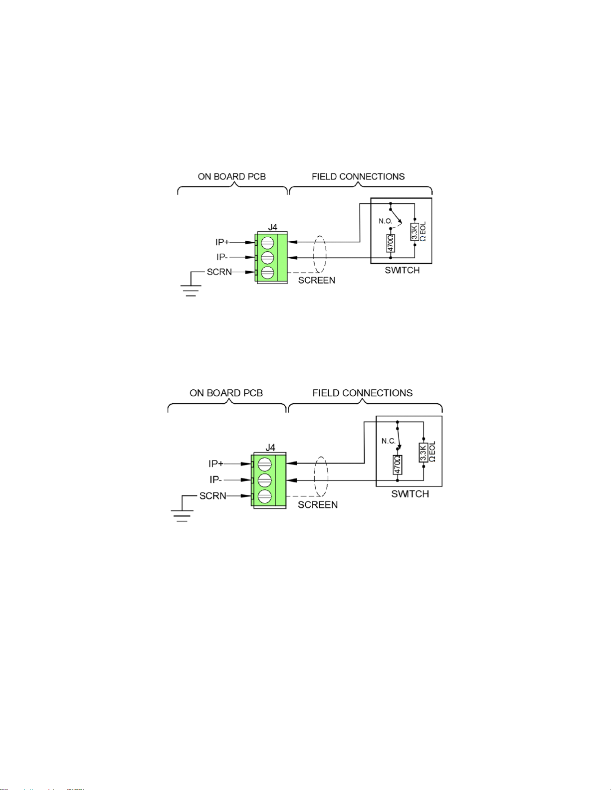
Input Connections (J4, J5, J6)
Input connections on Terminals J4, J5 and J6 are all contact closure inputs. The inputs can be individually
configured (via DIL switch SW2) to be normally open or normally closed. Figures 6 and 7 show how to
make input connections. All input connections are power limited and supervised.
The maximum cable length between the input device and the SRM must not exceed 3 metres.
Note: The triggering resistor used can be a 470Ωresistor (shown) or a 680Ω resistor.
Figure 6 –Normally Open Input Connection
Figure 7 –Normally Closed Input Connection

26-1369-01
11
Discharge pressure circuit (J4)
The following table shows state of the circuit based on connection type and switch position:
Switch Open
Switch Closed
Normally Open
Normal state
Active state
Normally Closed
Active state
Normal state
Normal state - Circuit is in Normal state.
Active state –The Discharge pressure switch is active which indicates that the extinguishing agent has
been released. The SRP Panel indicates this as a Released condition.
Bottle pressure switch circuit (J5)
The following table shows state of the circuit based on connection type and switch position:
Switch Open
Switch Closed
Normally Open
Normal state
Active state
Normally Closed
Active state
Normal state
Normal state - Circuit is in Normal state.
Active state –Bottle pressure switch is active which indicates that the pressurized container has a leak.
The SRP panel indicates this as a Fault condition.
Solenoid Missing circuit (J6)
The following table shows state of the circuit based on connection type and switch position:
Switch Open
Switch Closed
Normally Open
Normal state
Active state
Normally Closed
Active state
Normal state
Normal state - Circuit is in Normal state.
Active state –It indicates that the solenoid has been physically removed from the releasing agent
container for maintenance or testing. The SRP panel indicates this as a Fault condition.

26-1369-01
12
Acceptance Testing
Acceptance testing shall be performed in accordance with the requirements of BS7273 Pt1 : 2006,
requirements of the Local Authority Having Jurisdiction (AHJ), and the following requirements:
Note: before carrying out the following tests the Solenoid must not be connected to the suppression
container.
1. Temporarily disconnect the solenoid valve wires from the SRM and verify that a fault signal is
received by the SRP panel.
2. Temporarily switch off the end-of-line switch from the last SRM or disconnect the last SRM and
verify that a fault signal is received by the SRP panel.
3. Temporarily remove the end of line (EOL) resistor across the Solenoid Missing Input and verify
that a fault signal is received by the SRP panel. Repeat this for Bottle Pressure and Discharge
Pressure Inputs. These faults take approximately 60 seconds to be reported.
4. Temporarily trigger the Solenoid Missing Input by connecting a 470Ω or 680Ω resistor across IP+
and IP- terminals and verify that a fault signal is received by the SRP panel. Repeat this for the
Bottle Pressure Input. These faults take approximately 60 seconds to be reported.
5. Temporarily trigger the Discharge Pressure Input by connecting a 470Ω or 680Ω resistor across
IP+ and IP- terminals and verify that the system goes into a release state.
6. Verify the SRM Release LED illuminates and the solenoid valve operates.
7. Reset the SRP panel and verify that the SRM Release LED turns off.
8. Using either a manual release or the detection method of the panel, initiate the release mode.
9. Verify the SRM Release LED illuminates and the solenoid valve operates.
10. Reset the SRP panel and verify that the SRM Release LED turns off.
11. Verify that the SRM does not activate during any state other than Release for the programmed
Zone.
12. Secure the SRM front cover plate to the back box using the screws provided, as shown in
Figure 1 above. Make sure wiring is not pinched or excessive strain is not placed on the SRM
terminal block.

26-1369-01
13
Hardware Connections
After the acceptance tests connect the solenoid valve (Figure 8) according to the valve manufacturer’s
instructions.
Figure 8 –Solenoid Valve
Note: A discharge pressure switch (P/N 02-12534) must be installed on the discharge piping for
each container equipped with a manual release actuator (required as per
EN12094-1 Section 4.18 option with requirements).
Inspections & Testing
The suppression system(s) shall be inspected and tested in accordance with the requirements of
BS7273 Pt1 : 2006 and the Local Authority Having Jurisdiction (AHJ). Inspection and testing shall be
performed by the system installer or an approved maintenance company who has been trained on the
correct operation and testing of the system. Any defects should be recorded and reported to the person
responsible for routine testing.
A Supervision Assembly must be
used between the solenoid and
the SRM, see Figures 4 & 5.
The maximum cable length
between the solenoid and the
SRM must not exceed 3 metres.

26-1369-01
14
DIL Switch SW2 Settings
The SRM can be configured via an on board DIL switch SW2 as per the table below. The last device on
the zone circuit must have the EOL signal enabled (switch number 1 in the ‘ON’ position).
Switch
position
Configuration
1
OFF (Default) –Not an EOL device.
ON –EOL device.
2
OFF (Default) –The SRM indicates Released State only when a Discharge pressure switch
activates.
* ON –The SRM indicates Released State when a Solenoid coil is energized OR
a Discharge pressure switch activates.
NOTE: Only one SRM per zone circuit shall be set to activate the Discharge Pressure
Switch input.
3
OFF (Default) –Discharge pressure contact is Normally Open.
ON –Discharge pressure contact is Normally Closed.
4
OFF (Default) –Bottle pressure contact is Normally Open.
ON –Bottle pressure contact is Normally Closed.
5
OFF (Default) –Solenoid presence contact is Normally Open.
ON –Solenoid presence contact is Normally Closed.
6
Always OFF.
Unused.
7
Always OFF.
Used for Factory Test mode.
8
Always OFF.
Used for Factory Test mode.
* This option can be used when a Discharge pressure switch is not installed for Releasing pressure
confirmation. In that case the SRM can indicate a Released state as soon as the Solenoid coil is
energized.

26-1369-01
15
LED Table
LED Label
Pattern
Indication
State
Disabled
Fast Blink
SRM Disabled.
Disabled
Off
SRM Enabled.
Normal
Release
Fast Blink
Agent Released.
Released
Off
Agent not Released.
Normal
Discharge
Pressure
Fast Blink
Discharge pressure is high.
Release in process
Slow Blink
Discharge pressure switch wire short fault.
Fault
Very Slow Blink
Discharge pressure switch wire open fault.
Fault
Off
Discharge pressure is normal and wiring is good.
Normal
Bottle
Pressure
Fast Blink
Bottle pressure is low.
Fault
Slow Blink
Bottle pressure switch wire short fault.
Fault
Very Slow Blink
Bottle pressure switch wire open fault.
Fault
Off
Bottle pressure is normal and wiring is good.
Normal
Solenoid
Missing
Fast Blink
Release Tamper input activated
Fault
Slow Blink
Release Tamper input wire short fault.
Fault
Very Slow Blink
Release Tamper input wire open fault.
Fault
Very Slow Double
Blink
Solenoid coil open fault.
Fault
On Continuous
Solenoid coil short fault.
Fault
Off
No faults on Solenoid coil and Release Tamper
input is in Normal state.
Normal
Power
Fault
Fast Blink
External power is low.
Fault
Off
External Power is good.
Normal
Fault
Fast Blink
A Fault condition is present on the SRM.
Check other LEDs to determine the Fault type.
Fault
Off
No Fault present on the SRM.
Normal
Comms
Off
The SRM is not functional.
Fault
Momentary Blink
every 5 seconds
The SRM is functional and communicating with the
SRP panel.
Normal
Fast Blink –LED blinks once every ¼ second.
Slow Blink –LED Blinks once every 2 seconds.
Very Slow Blink –LED Blinks once every 5 seconds.
Very Slow Double Blink –LED Blinks twice every 5 seconds.

26-1369-01
16
Operation
Fault Monitoring –The SRM monitors all field wiring circuits for open and short faults. A fault is
indicated via on-board LEDs at the SRM. Fault type can be determined by observing the blink pattern of
active LEDs as listed in the LED table. Fault status is communicated to the SRP panel for indication at the
panel.
Disablement –The SRM can be disabled by disabling all releasing circuits at the SRP panel. The
disablement is indicated via the Disabled LED at the SRM. During disablement, the SRM does not
activate the solenoid automatically but it can still be activated manually via manual release actuator.
The SRM can be re-enabled by enabling all releasing circuits at the SRP panel.
Automatic Activation –The SRP panel signals the SRM to activate whenever the activation condition is
established. The SRM utilizes the external 24 volt power for solenoid activation. Based on the
DIL switch SW2 configuration setting, either the SRM waits for confirmation from the Discharge pressure
switch or it indicates a Released state as soon as the solenoid coil is energized.
Manual Activation –Manual activation is done by triggering the manual release actuator. A Discharge
pressure switch is required to indicate a Released state after a manual activation.

26-1369-01
17
Technical Data
Dimensions:
Overall Weight…………………………………………………
364g
Overall Size (W x H x D)……………………………………
189mm x 120mm x 56mm
Operating Temperature:
…………………………………………………………………………
-5oC to 40oC
Voltage Ranges:
Ext Supply………………………….…………………………….
24V to 28.5V DC
Zone Voltage……………….....................................
21.1V to 32V DC
Zone Operating Current
(Typical):
Quiescent………………………………………………………..
2.29mA
End of line ON (if applicable)……………………………
(in addition to Quiescent current)
0.07mA
Active……………………………………………………………….
5.58mA
Device Loading Units (DLUs)
…………………………………………………………………………
80
Number of devices per zone
…………………………………………………………………………
2
Solenoid:
…………………………………………………………………………
12V or 24V (see Solenoid
Connections on p6)
External Power Supply:
(for Solenoid)
…………………………………………………………………………
24V to 28.5V, 2A Max.
Max Cable Length to Inputs:
…………………………………………………………………………
3 Metres
Max Cable Length to Solenoid
…………………………………………………………………………
3 Metres
Flammability:
………………………………………………………………………..
UL94-V2
IP Rating:
…………………………………………………………………………
IP 30
Part Code:
…………………………………………………………………….….
100-0010

26-1369-01
18
Technical Support
Contact your supplier for technical support on this product.
Due to the complexity and inherent importance of a life risk type
system, training on this equipment is essential, and commissioning
should only be carried out by competent persons. Fike cannot
guarantee the operation of any equipment unless all documented
instructions are complied with, without variation. This unit
complies with the EMC directive.
Fike’s policy is one of continual improvement and the right to
change a specification at any time without notice is reserved.
Whilst every care has been taken to ensure that the contents of
this document are correct at time of publication, Fike shall be
under no liability whatsoever in respect of such contents. E&OE.
15
0843
Fike Safety Technology Ltd
Unit 31, Springvale Ind. Est.
Torfaen, NP44 5BD
15
DoP-100-0010
0843-CPR- 0222
Input/Output Device per EN54-18 ZA.3.
EN54-18:2005
100-0010
Intended for use in the fire detection and
fire alarm - Fixed fire fighting and gas
extinguishing systems in and around
buildings
Table of contents
Other Fike Control Unit manuals

Fike
Fike FIK-RVM User manual

Fike
Fike 55-043 User manual

Fike
Fike 55-046 User manual

Fike
Fike FAV User manual

Fike
Fike EIV User manual

Fike
Fike TWINFLEX IRM 100-0011 User manual

Fike
Fike P Service manual

Fike
Fike FIK-CR-6 User manual

Fike
Fike Lantronix XPort 10-2627 Operating instructions

Fike
Fike FIK-IM-10 User manual


Popular Control Unit manuals by other brands


Blonder tongue
Blonder tongue DAP Series instruction manual

Siemens
Siemens SITRANS F M MAG 8000 operating instructions

IBM
IBM BladeCenter Management Module installation guide

Eltek
Eltek flatpack2 user guide

unGer
unGer nLite HydroPower XXL manual

Pfeiffer Vacuum
Pfeiffer Vacuum HISCROLL operating instructions