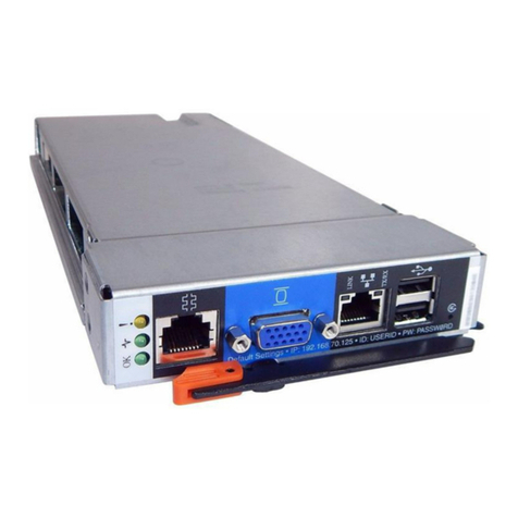
IBM BladeCenter Management Module User manual

IBM BladeCenter Server Connectivity Module
Installation Guide


IBM BladeCenter Server Connectivity Module
Installation Guide

Note:
Before using this information and the product it supports, read the Warranty Information
document, the general information in Appendix B, “Notices,” on page 29, and the
Important Notices document that comes with the product. Read the IBM System Safety
Notices and the License Agreement for Machine Code (LAMC) document on the IBM
Documentation CD. Read the Environmental Notices and User Guide on the IBM
Environmental Notices CD.
Third Edition (June 2012)
© Copyright IBM Corporation 2012.
US Government Users Restricted Rights – Use, duplication or disclosure restricted by
GSA ADP Schedule Contract with IBM Corp.

Contents
Safety ........................v
Chapter 1. Introduction ..................1
Related documentation ...................3
Features and specifications..................4
Standards .......................5
Notices and statements in this document .............6
Major components of the I/O module ..............7
Chapter 2. Installing and removing components .........9
Installation guidelines ...................9
Handling static-sensitive devices ...............10
Installing an I/O module ..................11
Removing an I/O module .................13
Chapter 3. Information panel LEDs and external ports .......15
Information panel ....................15
LEDs ........................16
Chapter 4. Updating the software and configuring the switch module 19
Chapter 5. Solving problems ................21
Running POST .....................21
POST errors ......................21
Chapter 6. Parts listing ..................23
Appendix A. Getting help and technical assistance ........25
Before you call .....................25
Using the documentation ..................25
Getting help and information from the World Wide Web .......26
Software service and support ................26
Hardware service and support ................26
IBM Taiwan product service .................27
Appendix B. Notices ...................29
Trademarks ......................30
Important notes .....................31
Product recycling and disposal ................31
Battery return program ..................33
Electronic emission notices .................34
Federal Communications Commission (FCC) statement.......34
© Copyright IBM Corp. 2012 iii

Industry Canada Class A emission compliance statement ......34
Avis de conformité à la réglementation d'Industrie Canada .....34
Australia and New Zealand Class A statement .........35
European Union EMC Directive conformance statement ......35
Germany Class A statement ................35
Deutschland: Einhaltung des Gesetzes über die elektromagnetische
Verträglichkeit von Geräten ..............36
Zulassungsbescheinigung laut dem Deutschen Gesetz über die
elektromagnetische Verträglichkeit von Geräten (EMVG) (bzw. der
EMC EG Richtlinie 2004/108/EG) für Geräte der Klasse A ....36
VCCI Class A statement .................36
Korea Communications Commission (KCC) statement .......37
Russia Electromagnetic Interference (EMI) Class A statement .....37
People's Republic of China Class A electronic emission statement . . . 37
Taiwan Class A compliance statement ............38
Electronic emission notices .................38
Federal Communications Commission (FCC) statement.......38
Industry Canada Class A emission compliance statement ......39
Avis de conformité à la réglementation d'Industrie Canada .....39
Australia and New Zealand Class A statement .........39
European Union EMC Directive conformance statement ......39
Germany Class A statement ................39
Deutschland: Einhaltung des Gesetzes über die elektromagnetische
Verträglichkeit von Geräten ..............40
Zulassungsbescheinigung laut dem Deutschen Gesetz über die
elektromagnetische Verträglichkeit von Geräten (EMVG) (bzw. der
EMC EG Richtlinie 2004/108/EG) für Geräte der Klasse A ....40
VCCI Class A statement .................41
Korea Communications Commission (KCC) statement .......41
Russia Electromagnetic Interference (EMI) Class A statement .....41
People's Republic of China Class A electronic emission statement . . . 41
Taiwan Class A compliance statement ............42
Index ........................43
iv Server Connectivity Module: Installation Guide
Safety
Before installing this product, read the Safety Information.
Antes de instalar este produto, leia as Informações de Segurança.
Læs sikkerhedsforskrifterne, før du installerer dette produkt.
Lees voordat u dit product installeert eerst de veiligheidsvoorschriften.
Ennen kuin asennat tämän tuotteen, lue turvaohjeet kohdasta Safety
Information.
Avant d'installer ce produit, lisez les consignes de sécurité.
Vor der Installation dieses Produkts die Sicherheitshinweise lesen.
Prima di installare questo prodotto, leggere le Informazioni sulla Sicurezza.
Les sikkerhetsinformasjonen (Safety Information) før du installerer dette
produktet.
© Copyright IBM Corp. 2012 v

Antes de instalar este produto, leia as Informações sobre Segurança.
Antes de instalar este producto, lea la información de seguridad.
Läs säkerhetsinformationen innan du installerar den här produkten.
Important:
All caution and danger statements in this documentation begin
with a number. This number is used to cross reference an English
caution or danger statement with translated versions of the caution
or danger statement in the IBM Safety Information book.
For example, if a caution statement begins with a number 1,
translations for that caution statement appear in the IBM Safety
Information book under statement 1.
Be sure to read all caution and danger statements in this
documentation before performing the instructions. Read any
additional safety information that comes with your server or
optional device before you install the device.
vi Server Connectivity Module: Installation Guide
Statement 1:
DANGER
Electrical current from power, telephone, and communication cables is
hazardous.
To avoid a shock hazard:
vDo not connect or disconnect any cables or perform installation,
maintenance, or reconfiguration of this product during an electrical
storm.
vConnect all power cords to a properly wired and grounded electrical
outlet.
vConnect to properly wired outlets any equipment that will be attached
to this product.
vWhen possible, use one hand only to connect or disconnect signal
cables.
vNever turn on any equipment when there is evidence of fire, water, or
structural damage.
vDisconnect the attached power cords, telecommunications systems,
networks, and modems before you open the device covers, unless
instructed otherwise in the installation and configuration procedures.
vConnect and disconnect cables as described in the following table
when installing, moving, or opening covers on this product or attached
devices.
To Connect: To Disconnect:
1. Turn everything OFF.
2. First, attach all cables to devices.
3. Attach signal cables to connectors.
4. Attach power cords to outlet.
5. Turn device ON.
1. Turn everything OFF.
2. First, remove power cords from outlet.
3. Remove signal cables from connectors.
4. Remove all cables from devices.
Safety vii

viii Server Connectivity Module: Installation Guide

Chapter 1. Introduction
This Installation Guide contains information about setting up, installing, and
configuring the IBM®BladeCenter®Server Connectivity Module.
For installation details, see Chapter 2, “Installing and removing components,”
on page 9. For additional information, see the instructions in your BladeCenter
unit documentation. The IBM BladeCenter Server Connectivity Module is also
referred to throughout this document as the switch module or I/O module.
You can obtain up-to-date information about the I/O module and other IBM
products at http://www.ibm.com/servers/eserver/support/xseries/
index.html.
.
Notes:
vUnless otherwise stated, references to the BladeCenter unit apply to all
BladeCenter unit types.
vChanges are made periodically to the IBM Web site. Procedures for locating
firmware and documentation might vary slightly from what is described in
this document.
vThe illustrations in this document might differ slightly from your hardware.
vThe sample screens that appear in this document might differ slightly from
the screens that are displayed by your system. Screen content varies
according to the type of BladeCenter unit and the firmware versions and
options that are installed.
vUnless otherwise stated, references to the management module apply to all
types of BladeCenter management modules.
© Copyright IBM Corp. 2012 1

Record information about the I/O module in the following table. The product
name and serial number are on the identification label on the side of the I/O
module. You will need this information when you register the I/O module
with IBM. You can register the I/O module at http://www.ibm.com/support/
mysupport/.
Product name IBM BladeCenter Server Connectivity Module
Serial number _________________________________________________
Other
identifiers _________________________________________________
The following illustration shows the locations of the identification label and the
serial number on the I/O module.
I/O module
Serial number/
identification label
1
2
3
4
5
6
TX/RX
TX/RX
TX/RX
TX/RX
TX/RX
TX/RX
LINK
SERVICE
ONLY
LINK
LINK
LINK
LINK
LINK
2Server Connectivity Module: Installation Guide
Related documentation
This Installation Guide contains setup, installation, configuration, and
troubleshooting instructions for the I/O module. This document also provides
general information about the I/O module, including warranty information,
and how to get help.
The following related documentation is in Portable Document Format (PDF) on
the BladeCenter Documentation CD that comes with your BladeCenter or
BladeCenter T unit:
vSafety Information
This document contains translated caution and danger statements. Each
caution and danger statement that appears in the documentation has a
number that you can use to locate the corresponding statement in your
language in the Safety Information document.
vBladeCenter Management Module User’s Guide
This document provides general information about the management module
for your BladeCenter or BladeCenter T unit type, including information
about features, how to configure the management module, and how to get
help.
vBladeCenter Management Module Command-Line Interface Reference Guide
This document explains how to use the management-module CLI to directly
access BladeCenter management functions as an alternative to using the
Web-based user interface. The CLI also provides access to the text-console
command prompt on each blade server through a Serial over LAN (SOL)
connection.
vIBM BladeCenter Serial over LAN Setup Guide
This document explains how to update and configure BladeCenter
components for SOL operation. The SOL connection provides access to the
text-console command prompt on each blade server, enabling the blade
servers to be managed from a remote location.
The most recent versions of this Installation Guide and all other BladeCenter
documentation are at http://www.ibm.com/servers/eserver/support/
bladecenter/index.html.
Chapter 1. Introduction 3

Features and specifications
This section provides a summary of the features and specifications that apply
to the Server Connectivity Module for IBM BladeCenter. For detailed
information about the features, see the IBM BladeCenter Server Connectivity
Module User’s Guide.
Table 1. Features and specifications
vSimple Configuration and Control: This device should be configurable by a
non-networking system administrator through a graphical user interface (GUI) or a
command-line interface (CLI). Typical networking concepts, such as spanning tree
redundancy, virtual local area networks (VLANs), port filters, link aggregation, port
trunks, and remote monitoring (RMON) statistics are not typically used or
understood by this class of administrator. The default operation will be to hide the
underlying networking function and configuration from the user. Some functions,
such as Spanning Tree Protocol, are eliminated since they are not required. Only a
few simple networking parameters are available to the user to configure and control
the Server Connectivity Module.
vPorts
– Internal ports
- Fourteen internal full-duplex Gigabit ports, one connected to each of the blade
servers in the BladeCenter unit. Eight internal links in a BladeCenter-T chassis.
- Two internal full-duplex 100 Mbps ports connected to the management module
in slots 1 and 2.
– External copper ports
- Six external ports are provided using standard Category 5 enhanced (5e) copper
cable connectors.
- 10/100/1000 Mbps interfaces: The external ports connect at 10 Mbps Full
Duplex, 100 Mbps Full Duplex, or 1 Gbps Full Duplex.
- Auto-negotiation capability.
- Copper connection for making connections to a backbone, end stations, and
servers.
vInternal Switching: This device provides packet switching between the blade servers
and management modules within the chassis to support Serial over LAN (SOL) and
other future traffic flows. Blade-server-to-blade-server switching is supported for
those blade server ports that are assigned to a common group. This support does not
require explicit configuration to be operational.
vConfiguration of the Server Connectivity Module is only through a connection to a
management-module port and not through the external switch ports.
vSupport for tagged VLANs: The administrator can define VLAN identifiers (IDs) to
match specific server application requirements.
vCisco EtherChannel compatible static link aggregation.
vManagement-module control that allows for external ports to be enabled or disabled.
vSupport for Ethernet jumbo frame formats (up to 9K bytes per frame).
4Server Connectivity Module: Installation Guide
Table 1. Features and specifications (continued)
vTwo independent internal 100 Mbps FDX links connected to each of two
management modules (jumbo frame support not required on these links).
vManagement-module I2C interface that provides VPD and register access.
vLevel-2 (L2) switching per current industry standards and practice.
v“Non-networking” device appearance allows administration and installation of this
device by the system manager rather than a network administrator.
vPort aggregation (external ports).
vPort group failover (triggered by external ports).
vIEEE 802.3x Flow Control.
vInternet group multicast protocol (IGMP) snooping.
vIEEE 802.1Q support for SOL and optional user VLAN tagging of external ports.
vAn embedded central processing subsystem for initialization, configuration, and
management.
vRADIUS or TACACS+ user authentication.
vNetwork cables
– 10BASE-T:
- UTP Category 3, 4, 5 (100 meters or 328.1 ft maximum)
- 100-ohm STP (100 meters or 328.1 ft maximum)
– 100BASE-TX:
- UTP Category 5 (100 meters or 328.1 ft maximum)
- EIA/TIA-568 100-ohm STP (100 meters or 328.1 ft maximum)
– 1000BASE-T:
- UTP Category 6 (standard for 1 GB devices)
- UTP Category 5e (100 meters or 328.1 ft maximum)
- UTP Category 5 (100 meters or 328.1 ft maximum)
- EIA/TIA-568B 100-ohm STP (100 meters or 328.1 ft maximum)
Standards
The Server Connectivity Module supports the following Institute of Electrical
and Electronics Engineers (IEEE) standards:
vIEEE 802.3x
vIEEE 802.1Q (tagged) VLANs
Chapter 1. Introduction 5

Notices and statements in this document
The caution and danger statements that appear in this document are also in
the multilingual Safety Information document, which is on the IBM BladeCenter
Documentation CD. Each statement is numbered for reference to the
corresponding statement in the Safety Information document.
The following notices and statements are used in this document:
vNote: These notices provide important tips, guidance, or advice.
vImportant: These notices provide information or advice that might help you
avoid inconvenient or problem situations.
vAttention: These notices indicate possible damage to programs, devices, or
data. An attention notice is placed just before the instruction or situation in
which damage could occur.
vCaution: These statements indicate situations that can be potentially
hazardous to you. A caution statement is placed just before the description
of a potentially hazardous procedure step or situation.
vDanger: These statements indicate situations that can be potentially lethal or
extremely hazardous to you. A danger statement is placed just before the
description of a potentially lethal or extremely hazardous procedure step or
situation.
6Server Connectivity Module: Installation Guide
Major components of the I/O module
Orange on the release latch on the I/O module identifies this device as a
hot-swap component. You can install or remove this component while the
BladeCenter unit is running.
The following illustration shows the major components of the I/O module.
Note: The illustrations in this document might differ slightly from your
hardware.
Serial number/
identification label
1
2
3
4
5
6
TX/RX
TX/RX
TX/RX
TX/RX
TX/RX
TX/RX
LINK
SERVICE
ONLY
LINK
LINK
LINK
LINK
LINK
Release latch
Information panel
Ethernet ports (6)
For more information about the components of the information panel, see
Chapter 3, “Information panel LEDs and external ports,” on page 15.
Chapter 1. Introduction 7

8Server Connectivity Module: Installation Guide
Chapter 2. Installing and removing components
See the Installation and User’s Guide for your BladeCenter unit type for
information about the I/O-module bay locations in the BladeCenter unit and
specific requirements for installing I/O modules in your BladeCenter unit.
Attention: To maintain proper system cooling, each I/O-module bay must
contain either an I/O module or a filler module.
For details about network interface requirements and expansion options, see
the following documents:
vInstallation and User’s Guide for your BladeCenter unit type
vInstallation and User’s Guide for each blade server type
Installation guidelines
Before you begin to install the I/O module in your BladeCenter unit, read the
following information:
vRead the safety information that begins on page v and the guidelines in
“Handling static-sensitive devices” on page 10, and read the safety
statements in the BladeCenter unit publications. This information will help
you work safely.
vObserve good housekeeping in the area where you are working. Place
removed covers and other parts in a safe place.
vDo not attempt to lift an object that you think is too heavy for you. If you
have to lift a heavy object, observe the following precautions:
– Make sure that you can stand safely without slipping.
– Distribute the weight of the object equally between your feet.
– Use a slow lifting force. Never move suddenly or twist when you lift a
heavy object.
– To avoid straining the muscles in your back, lift by standing or by
pushing up with your leg muscles.
vMake sure that you have an adequate number of properly grounded
electrical outlets for the BladeCenter unit, monitor, and other devices.
vBack up all important data before you make changes to disk drives.
vHave a small flat-blade screwdriver available.
vYou do not have to turn off the BladeCenter unit to install or replace any of
the hot-swap modules in the BladeCenter unit.
vOrange on the release latch on the I/O module identifies this device as a
hot-swap component. You can install or remove this component while the
© Copyright IBM Corp. 2012 9

BladeCenter unit is running. See the instructions in this chapter for more
information about installing or removing hot-swap or hot-plug components.
vIf you plan to install additional I/O modules in the I/O-module bays of
your BladeCenter unit, you might also have to install an I/O expansion card
in the applicable blade server to support the I/O modules in these bays. For
information about the types of compatible I/O expansion cards for the blade
servers, contact your IBM authorized reseller. See the I/O expansion card
documentation for details about I/O expansion card installation,
configuration, and use.
vWhen you are finished working on the I/O module and all other
BladeCenter unit components, reinstall all safety shields, guards, labels, and
ground wires.
vFor a list of supported options for the I/O module, see http://
www.ibm.com/servers/eserver/serverproven/compat/us/.
Handling static-sensitive devices
Attention: Static electricity can damage the system and other electronic
devices. To avoid damage, keep static-sensitive devices in their static-protective
packages until you are ready to install them.
To reduce the possibility of electrostatic discharge, observe the following
precautions:
vLimit your movement. Movement can cause static electricity to build up
around you.
vHandle the device carefully, holding it by its edges or its frame.
vDo not touch solder joints, pins, or exposed circuitry.
vDo not leave the device where others can handle and damage it.
vWhile the device is still in its static-protective package, touch it to an
unpainted metal part of the BladeCenter unit or any unpainted metal surface
on any other grounded rack component in the rack in which you are
installing the device for at least 2 seconds. This drains static electricity from
the package and from your body.
vRemove the device from its package and install it directly into the
BladeCenter unit without setting down the device. If it is necessary to set
down the device, put it back into its static-protective package. Do not place
the device on the BladeCenter chassis or on a metal surface.
vTake additional care when handling devices during cold weather. Heating
reduces indoor humidity and increases static electricity.
10 Server Connectivity Module: Installation Guide
Other manuals for BladeCenter Management Module
4
Table of contents
Other IBM Control Unit manuals

IBM
IBM 3270 User manual

IBM
IBM MegaBasic IC697PCM711 User manual

IBM
IBM 5294 Manual

IBM
IBM 3274 User manual

IBM
IBM BladeCenter 4-Port User manual

IBM
IBM 4769 User manual

IBM
IBM BladeCenter Advanced Management Module User manual

IBM
IBM 2702 Technical manual

IBM
IBM 5394 User manual

IBM
IBM 8271 Nways Ethernet LAN Switch User manual

IBM
IBM 8260 User manual

IBM
IBM WebSphere DataPower XI50B User manual

IBM
IBM Redbooks ServeRAID-MR10k User manual

IBM
IBM BladeCenter Copper Pass-thru User manual

IBM
IBM AR-B3001 User manual

IBM
IBM Power System PCIe3 User manual

IBM
IBM 3274 51C Setup guide

IBM
IBM 1620 Manual

IBM
IBM 8250 User manual

IBM
IBM color LaserJet 5500 Operating manual