manuals.online logo
Brands
  1. Home
  2. •
  3. Brands
  4. •
  5. Fike
  6. •
  7. Control Unit
  8. •
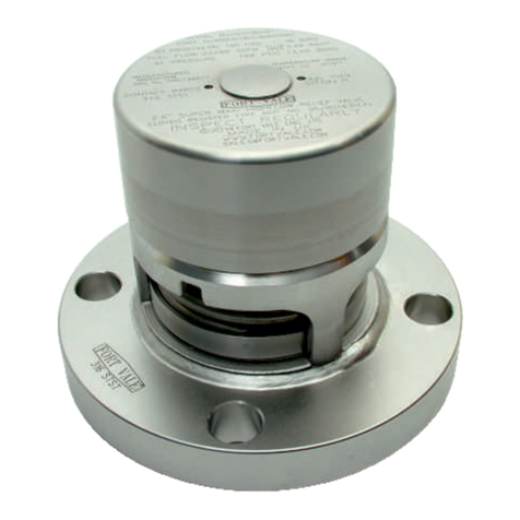
  9. Fike P Service manual

Fike P Service manual

WARNING
• Read these instructions carefully and completely
before attempting to unpack, install or service the
rupture disc and holder.
• Do not vent a rupture disc assembly to an area
where it would endanger personnel.
• Install the rupture disc assembly in such a way
that equipment in the area will not prevent rupture
disc from opening or be damaged by system dis-
charge.
INSTALLATION INSTRUCTIONS
Screw Type Rupture Disc Assemblies
Includesmodels:P, PV, CPV, CPV-C, CPC, HO, HOV, PLHO, PLHOV
Scored:SCRD,SCRD-V
• Abaffleplateontheoutletendofventpipingdoes
NOTnecessarilypreventpotentiallydangerousdis-
charge.
• Piping should be braced to absorb shock when
the rupture disc ruptures.
• Install the enclosed DANGER sign in a conspicu-
ous location near the zone of potential danger.
INSPECTION/PREPARATION
A. NEW RUPTURE DISCS
WARNING: Always handle the rupture disc by its edges
only. Damage to the dome or seat area of the rupture
disc may adversely affect the performance of the rup-
ture disc. Read the rupture disc tag completely before
installing to confirm that the size, burst information,
and type are correct for your system.
1. Carefullyremove therupturediscfromits packagingcon-
tainer.
2. Remove and discard the shipping support (if provided).
ShippingsupportshaveORANGESTICKERSonthem-they
areNOTa partof therupture disc.(SeeFigure1)
SHIPPING SUPPORT ONLY.
DO NOT USE
FOR RUPTURE DISC.
Figure1
PLHOandPLHOVusers:DONOTdiscard theclear plastic
that is attached to the tag. It is a component of the disc.
3. Inspect the rupture disc for damage. Look for dents,
scratches or dings in the seat area or dents in the dome of
therupturedisc. (SeeFigure 2)
Figure2
4. If foreign material is present, carefully clean the rupture
disc with a solvent that is compatible with your media.
B. NEW HOLDER
Handle rupture disc holders with care. Damage to the
rupture disc holder could affect the performance of the
rupture disc.
1. Afterremovingtherupturedisc holderfromits packaging,
unscrewtheholddownnutanddisassemble.
2. Discard the white shipping protector which is between
thebase andholddown.
3. Inspect the seat area for scratches, dents, nicks or dirt.
Flawsmay adverselyaffect sealinganddiscburstpressure.
06-246-1
C. EXISTING HOLDER
1. For ease of installation, carefully remove the rupture
disc assembly from piping. (See Figures 3 and 4)
2. Separaterupturedisc holdercomponents.
3. Remove the rupture disc from its holder.
4. Inspectthe seatarea ofthe rupturedisc holder. Lookfor
scratches,nicks,corrosionordepositsleftfromthemedia.
5. If necessary, clean the seat area with a solvent that is
compatible with your media. If this does not remove dirt,
handpolish theseatarea withScotchBrite,fine emery cloth
or #0000 steel wool. DO NOT MACHINE THE RUPTURE
DISC HOLDER! If scratches, nicks, corrosion or deposits
from the media cannot be removed by hand, contact the
factory.
D. ASSEMBLY
WARNING: Before attempting to assemble the rupture
discand rupture disc holder, confirm thatthe seat area
of the rupture disc is designed to fit the rupture disc
holder.
1. Place rupture disc in the inlet of the rupture disc holder
with the dome pointing in the direction of flow.
2. Place the holddown ring on the rupture disc. Refer to
Figure 3 for proper orientation of 30oseat and Figure 4 for
properorientationofflatseat.
3. Screw the outlet into place, hand tight.
4. Check holder rating and type located on the side of the
holder. Refer to Table 1 for torque values. Locate the table
with the corresponding type and rating. Locate burst pres-
sure.The column to the right contains the required torque in
ft-lbs.
5. Torque holddown nut to required torque.
Figure 4: Screw Type - Flat Seat
WARNING: Inversion of the holddown ring (installing
the ring upside down) may result in unexpected
performance characteristics, such as premature
opening or increased burst pressures.
Figure 3: Screw Type - 30oSeat
E. INSTALLATION
1. Ifnecessary,clean NPTthreadson theholder.Wirebrush-
ing is usually sufficient. Seal threads withTeflon® tape or
pipethread sealant.
2. Thread screw type assembly into the installation. One-
halfturnpasthandtightis recommended.Alwaysapplytorque
using the flats nearest to the end being installed.
3. Experience has shown that, in some installation condi-
tions, it may be necessary to re-torque the assembly after
thesystem has operated through normal pressure and tem-
peraturecycles.
Under normal operating conditions, the rupture disc should
bereplaced yearly. Severe operating conditions mayrequire
thattherupture disc be replaced more frequently.
4. Themetal tag shall be attached to theST assembly in a
manner that will prevent changing the rupture disc without
breaking the seal. Reference figures 5 showing the tag at-
tached using a lead shunt and 0.02” SST wire as recom-
mendedpractice. Figure 5-ScrewType
)ISP0003(epyTwercS03"2/1 )ISP00001(epyTwercS001"2/1
erusserPtsruB 27@gisp
o
FscsiDdiloS bl-tf csiDtfoS bl-tf erusserPtsruB 27@gisp
o
FscsiDdiloS bl-tf csiDtfoS bl-tf
005otniM5111 005otniM0303
0001ot005>0291 0001ot005>8383
0051ot0001>52- 0002ot0001>25-
0002ot0051>03- 0003ot0002>66-
0052ot0002>53- 0004ot0003>18-
0003ot0052>04- 0005ot0004>69-
0006ot0005>011-
)ISP00051(epyTwercS051"2/1 0007ot0006>021-
005ot00303 0008ot0007>031-
0001ot005>8383 0009ot0008>041-
0002ot0001>25- 00001ot0009>051-
0003ot0002>66-
0004ot0003>18- )ISP0003(epyTwercS03"4/3
0005ot0004>69- 005ot08643
0006ot0005>011- 0001ot005>5783
0007ot0006>021- 0051ot0001>38-
0008ot0007>031- 0002ot0051>09-
0009ot0008>041- 0052ot0002>89-
00001ot0009>051- 0003ot0052>501-
00521ot00001>571-
00051ot00521>002-
Table 1
704 South 10th Street • Blue Springs, Missouri 64015 U.S.A.
Phone 816 229-3405 • Fax (816) 228-9277 • e-mail [email protected] • www.fike.com
P/N 06-246-1-4 Copyright ©2005 by Fike Corporation All rights reserved
Table 1 (continued)
Soft Disc Types
Seals:Silver(Ag), Gold (Au),Aluminum(Al),Teflon
(FEP and PFA)
Liners:Teflon(FEPand PFA)
Coatings:Teflon (FEP), UrethaneAcrylic, Urethane
Solid Disc Types
Seals:Hastelloy(C-276),Titanium (Ti)Tantalum
(Ta), 316 SST, Inconel, Monel,Nickel (Ni)
Liners:Lead (Pb)
Coatings:Gold (Au),Teflon (FEP), Urethane
Acrylic,Urethane
NOTE: In the event of a conflict between solid and
soft discs, the soft disc torque shall be used.
NOTE: Rupture disc specifications and year of
manufacture can be found on the rupture disc tag.
)ISP00051(epyTwercS051"4/3 )ISP0005(epyTwercS05"1
005ot05454005ot05454
0001ot005>85850001ot005>9595
0002ot0001>87- 0051ot0001>17-
0003ot0002>001- 0002ot0051>38-
0004ot0003>221- 0052ot0002>69-
0005ot0004>541- 0003ot0052>701-
0006ot0005>761- 0053ot0003>121-
0007ot0006>181- 0004ot0053>431-
0008ot0007>691- 0054ot0004>741-
0009ot0008>212- 0005ot0054>061-
00001ot0009>722-
00521ot00001>462-
00051ot00521>103-

This manual suits for next models

10

Other Fike Control Unit manuals

Fike TWINFLEX SRM 100-0010 User manual

Fike

Fike TWINFLEX SRM 100-0010 User manual

Fike 55-046 User manual

Fike

Fike 55-046 User manual

Fike FIK-M500M User manual

Fike

Fike FIK-M500M User manual

Fike FIK-FML Technical manual

Fike

Fike FIK-FML Technical manual

Fike FAV User manual

Fike

Fike FAV User manual

Fike MICROMIST 10-2340 User manual

Fike

Fike MICROMIST 10-2340 User manual

Fike EIV User manual

Fike

Fike EIV User manual

Fike FIK-IM-10 User manual

Fike

Fike FIK-IM-10 User manual

Fike TWINFLEX IRM 100-0011 User manual

Fike

Fike TWINFLEX IRM 100-0011 User manual

Fike FIK-RVM User manual

Fike

Fike FIK-RVM User manual

Fike FIK-CR-6 User manual

Fike

Fike FIK-CR-6 User manual

Fike 55-043 User manual

Fike

Fike 55-043 User manual

Fike Lantronix XPort 10-2627 Operating instructions

Fike

Fike Lantronix XPort 10-2627 Operating instructions

Popular Control Unit manuals by other brands

MS Sedco Commander PTM installation instructions

MS Sedco

MS Sedco Commander PTM installation instructions

Huawei ME909 Series Hardware guide

Huawei

Huawei ME909 Series Hardware guide

ZLG CANFDNET-400U user manual

ZLG

ZLG CANFDNET-400U user manual

Automationdirect.com Productivity 2000 P2-08TD2S manual

Automationdirect.com

Automationdirect.com Productivity 2000 P2-08TD2S manual

THORLABS LD2000R user guide

THORLABS

THORLABS LD2000R user guide

Honeywell VSxF-2 installation instructions

Honeywell

Honeywell VSxF-2 installation instructions

ICP DAS USA ZT-257 Series quick start guide

ICP DAS USA

ICP DAS USA ZT-257 Series quick start guide

Gemalto Cinterion BGS2-W miniPCIe Hardware interface description

Gemalto

Gemalto Cinterion BGS2-W miniPCIe Hardware interface description

Bradley Navigator S59-4007 installation manual

Bradley

Bradley Navigator S59-4007 installation manual

ATEQ G6 Series manual

ATEQ

ATEQ G6 Series manual

THOMSON Grass Valley KAM-XM Series instruction manual

THOMSON

THOMSON Grass Valley KAM-XM Series instruction manual

YOKOGAWA FN510 user manual

YOKOGAWA

YOKOGAWA FN510 user manual

TOPP TF21 Installation and use instructions

TOPP

TOPP TF21 Installation and use instructions

Quectel GSM Series Audio Design Guide

Quectel

Quectel GSM Series Audio Design Guide

National Instruments NI 9759 user manual

National Instruments

National Instruments NI 9759 user manual

Nice RC2 Instructions and warnings for installation and use

Nice

Nice RC2 Instructions and warnings for installation and use

Emerson BM6X Series instruction manual

Emerson

Emerson BM6X Series instruction manual

Controls XCAN-AC product manual

Controls

Controls XCAN-AC product manual

manuals.online logo
manuals.online logoBrands
  • About & Mission
  • Contact us
  • Privacy Policy
  • Terms and Conditions

Copyright 2025 Manuals.Online. All Rights Reserved.