FIKE CORPORATION
Micromist Interface Module User Guide Page 5 of 17
Manual P/N: 06-218 Rev. 1, 06/01
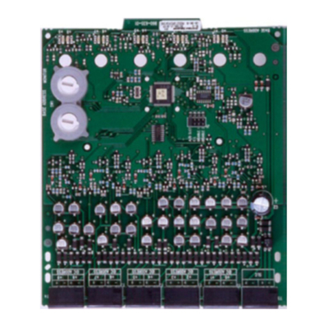
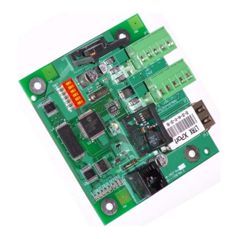
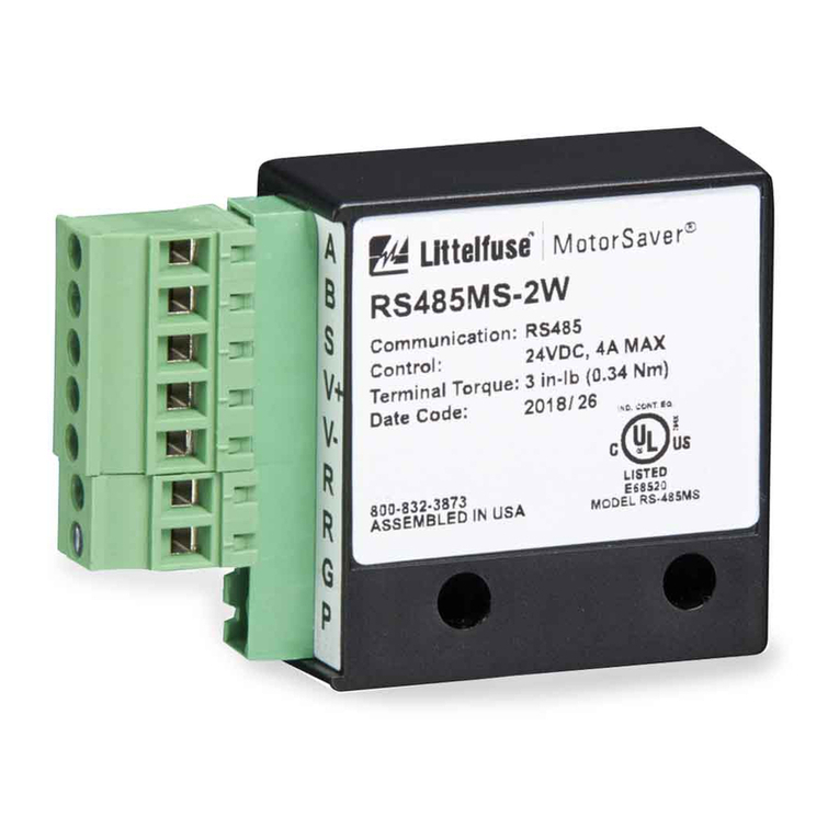
The following will describe each terminal block and it’s function.
P1 - Power Input
This circuit is for 24VDC power input. The terminal block is four positions; providing +/- inputs
coming to the module and +/- going out of the module to the next device requiring 24VDC power
as necessary.
Releasing Initiating Circuits
(installation will only use one of the two Releasing inputs – P2 or P3):
P2 - Contact Closure Releasing Input
This circuit will monitor the normally open alarm contacts on the FACP. Once the contacts
close, it will initiate the solenoid cycling sequence that controls the Micromist containers.
This circuit supports Class A wiring and will supervise the cabling between the module and
the FACP for Open, Normal, Activation, and Short Circuit conditions. See Figures 1 and 2 in
Section 4.1, Wiring Diagrams.
OR
P3 - Polarity Reversal Releasing Input
This circuit is activated by the 24VDC Polarity reversal from the FACP. Once the reversal
occurs, the module will initiate the solenoid cycling sequence that controls the Micromist
containers. Supervision of this circuit will be provided by the FACP, class B wiring only.
See Figures 3 and 4 in Section 4.1, Wiring Diagrams.
P4 - Disable Circuit
Contact Closure Disable Input: This circuit will monitor the normally open contacts of a keyed,
selector switch. Once the contacts close, the solenoid output will become disabled. The module
will resume operation once the disable contacts return to their normal open state. This circuit
supports Class A or B wiring and will supervise the cabling between the module and the disable
switch for Open, Normal, Activation, and Short Circuit conditions. See Figures 3 and 4 in
Section 4.1, Wiring Diagrams.
P5 - Solenoid Output Circuit (Terminals 1 & 2)
The solenoid output circuit will cycle the two 12Vdc solenoids in series, or two 24Vdc solenoids in
parallel, which control the waterflow of the Micromist system. The cycle on/off times are
dependent upon the hazard being protected (turbine generator vs. machinery space). The cycle
on/off times will be configured on the module via the dipswitch settings as depicted in Section 5.0,
Programming. This circuit will supervise the cabling between the module and the solenoids for
Open, Normal, and Short Circuit conditions. See Figure 1 in Section 4.1 for example wiring
diagrams
P5 - Dry Contact Output (Terminals 3, 4 & 5)
The module will provide a single, Form C dry contact output for annunciation of a trouble
condition on the Micromist Interface Module. Supervision of the contacts will be provided by the
FACP.
2.4 PART NUMBERS / REPLACEMENT PARTS
02-4181 Fuse, 2Amp, Miniature Automotive, Littlefuse 297002
02-9116 Terminal Block with Screws, 4 position
02-4932 Terminal Block with Screws, 5 position


