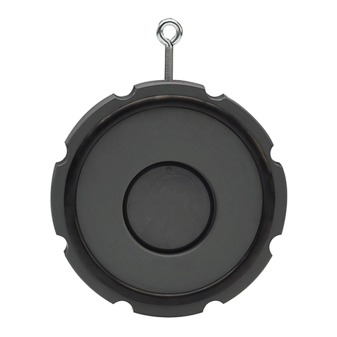
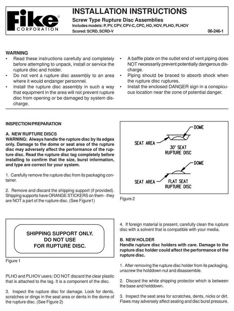
Fike EIV User manual

INSTALLATION & OPERATION
MANUAL
P/N: E06-017-1 (Rev. 2 / January, 2015)
EXPLOSION ISOLATION VALVES

This page intentionally left blank

REVISION HISTORY
Document P/N: E06-017-1
Original Release Date.................................................................................................................................June, 1999
Revision / Description of Change Revision Date
Revision 1.........................................................................................................................................September, 1999
Revision 2..............................................................................................................................................January, 2015
1) Changed manual P/N to E06-017-1.
2) Restructured document and updated format
3) Combined Sections “GCA Installation Procedure” and “GCA Removal Procedure,” removed steps, and
replaced with note “GCA’s are to be handled, installed and removed by a certified technician only.”
4) Removed Section “Identification of Valve.”
5) Renamed Section “Valve Installation” to “Mounting Orientation” and moved notes referring to support
concerns to Section “Support Considerations.”
6) Added weather cover note to Section 2.1 “Installation.”
7) Removed “The red and blue leads are provided for cross zone connections only” from Note in Section 2.3
“Gas Cartridge Actuator (GCA).”
8) Updated Gate Position Sensor wiring diagram in Figure 5.
9) Removed Sections “Refurbishment Instructions,”“Refurbish Kits,” “Supply Materials,”“Scheduled
Maintenance,” and “Maintenance after each Activation” completely.
10) Added Sections “Muffler” and “Spare Parts.”
11) Removed Tables “Refurbish Kits,” “Replacement Parts,” and “Assembly Torque (Ft-Lbs).”
12) Corrected stud quantities in Table “EIV Specifications.”
13) Updated all part numbers, tables and figures, where necessary, throughout.

This page intentionally left blank

TABLE OF CONTENTS
January, 2015 Document P/N: E06-017-1 (Rev 2)
Page No.
INTRODUCTION........................................................................................................................................................1
1.0 GENERAL INFORMATION...........................................................................................................................1
1.1 Description......................................................................................................................................1
1.2 Service Qualifications....................................................................................................................1
1.3 Personnel Safety ............................................................................................................................1
2.0 GCA ACTUATED ISOLATION VALVE –E30-016-XX-YY ..........................................................................2
2.1 Installation.......................................................................................................................................2
2.1.1 Mounting Orientation...........................................................................................................2
2.1.2 Valve Location.....................................................................................................................3
2.1.3 Support Considerations.......................................................................................................3
2.2 Valve Parts ......................................................................................................................................4
2.3 Gas Cartridge Actuator (GCA).......................................................................................................5
2.3.1 GCA Safety Procedures......................................................................................................5
2.3.2 GCA Installation and Removal ............................................................................................6
2.3.3 GCA Fittings ........................................................................................................................6
2.4 Gate Position Sensors ...................................................................................................................7
2.4.1 Installation Instructions –Gate Sensor................................................................................7
2.5 Lockout Pin.....................................................................................................................................9
2.6 Muffler..............................................................................................................................................9
2.7 EIV Specifications ........................................................................................................................10
2.8 GCA Fittings and Wiring Diagrams ............................................................................................13

TABLE OF CONTENTS
January, 2015 Document P/N: E06-017-1 (Rev 2)
TABLES
TABLE 1 –EIV SPECIFICATIONS (REF. FIGURES 8 AND 9)...............................................................................10
FIGURES
FIGURE 1 –MOUNTING ORIENTATION..................................................................................................................2
FIGURE 2 –VALVE LIFTING POINTS......................................................................................................................3
FIGURE 3 –VALVE PARTS ......................................................................................................................................4
FIGURE 4 –GCA COMPONENT DETAILS...............................................................................................................5
FIGURE 5 –GATE SENSOR WIRING SCHEMATIC................................................................................................8
FIGURE 6 –LOCKOUT PIN.......................................................................................................................................9
FIGURE 7 –MUFFLER..............................................................................................................................................9
FIGURE 8 –EIV SPECIFICATIONS (2" –10" SIZES).............................................................................................11
FIGURE 9 –EIV SPECIFICATIONS (12" –24" SIZES)...........................................................................................12
FIGURE 10 –GCA / SERIES WIRING (2" –10" EIV)..............................................................................................13
FIGURE 11 –GCA / SERIES WIRING (12" –18" EIV)............................................................................................14
FIGURE 12 –GCA / SERIES WIRING (20" –24" EIV)............................................................................................15

EXPLOSION ISOLATION VALVE
INSTALLATION & OPERATION MANUAL
January, 2015 Document P/N: E06-017-1 (Rev 2) Page: 1
INTRODUCTION
This manual is intended to provide installers with comprehensive information pertaining to the installation of Fike
Explosion Isolation Valves. This information should be used in conjunction with the field installation drawings
provided for the specific application.
1.0 GENERAL INFORMATION
1.1 DESCRIPTION
The Fike Explosion Isolation Valve (EIV) is used in conjunction with other Fike Explosion Protection System
components to prevent the propagation of a flame front through ducts or conveying lines to additional equipment
or occupied areas. The Fike EIV provides a positive mechanical seal in process piping or ducts when activated
by the system controller. The Fike EIV has a stainless steel full ported conduit gate. The pipe flanges fit ANSI
150 bolting. The modular construction of the Fike EIV allows on-site refurbishment and/or rebuilding; typically
without removing the valve from the process piping.
The principal function of the EIV is to rapidly close the pipe or duct to prevent further travel of the deflagration
flame front. Valve closure is initiated when the system controller sends an activation signal to an electrically
actuated cartridge device. This cartridge device generates a high volume, instantaneous pressure that moves a
pneumatic piston connected to the gate. This closed gate seals off the pipe or duct preventing the passage of
flame to other equipment or personnel occupied areas.
1.2 SERVICE QUALIFICATIONS
The information contained in this document is provided for reference purposes. For information on Fike
certification and training programs, factory service and ordering replacement parts, contact Fike Product Support
Department by calling 816-229-3405.
1.3 PERSONNEL SAFETY
WARNING: Approved eye protection shall be used when performing any maintenance procedure.
WARNING: The GCA shall not be installed until the EIV and control system are installed and checked for
proper operation.
WARNING: The GCA shall only be installed by Fike certified personnel.
WARNING: To prevent possible injury, the GCA shall be disconnected and shunted prior to performing
maintenance on the EIV.
WARNING: When performing maintenance on the valve which exposes internal components, the lockout pin
shall be secured to prevent accidental movement of the gate, piston and piston rod.

EXPLOSION ISOLATION VALVE
INSTALLATION & OPERATION MANUAL
January, 2015 Document P/N: E06-017-1 (Rev 2) Page: 2
2.0 GCA ACTUATED ISOLATION VALVE –E30-016-XX-YY
2.1 INSTALLATION
2.1.1 MOUNTING ORIENTATION
The valve must be oriented so that the gate is not moving upwards while closing. Valve sizes up through 18"
shall be positioned within the limits shown below, and valve sizes 20" and 24" shall only be mounted in an upright
position so that the gate travels downward during closure (refer to Figure 1).
For ease of maintenance a two foot removable process line section may optionally be installed on either side of
the valve. Additionally, an area of approximately two feet around the EIV should be left clear to allow access to
EIV components for maintenance and rebuild procedures.
Installing a weather cover is strongly suggested for an outdoor installation of an EIV. This will help shield against
rain and precipitation.
2" –18" Mounting Orientation 20" and 24" Mounting Orientation
FIGURE 1 –MOUNTING ORIENTATION
GCA
Allmaintenance shall be performed by
FIKEcertified technicians only. The
GCAleads shall be electrically
disconnectedand shunted and theGCA
removedfrom the valvebefore
performingany maintenance. Reference
theFike I&O Manual, E06-018.
Allmaintenance shall be performed by
FIKEcertified technicians only. The
GCAleads shall be electrically
disconnectedand shunted and theGCA
removedfrom the valvebefore
performingany maintenance. Reference
theFike I&O Manual, E06-018.
GCA
Valve shall be
mounted within
90° of vertical
(Side to Side)
Valve shall be
mounted within
90° of vertical
(Front to Rear)

EXPLOSION ISOLATION VALVE
INSTALLATION & OPERATION MANUAL
January, 2015 Document P/N: E06-017-1 (Rev 2) Page: 3
2.1.2 VALVE LOCATION
The Fike EIV must be installed at the specific location as detailed on the system design drawing. Failure to locate
the EIV as detailed on the system drawing could result in the protection system being unable to stop the flame
front, potentially causing catastrophic failure and injury to plant personnel. Careful consideration should be taken
when mounting and supporting the EIV.
2.1.3 SUPPORT CONSIDERATIONS
Valves shall be supported to prevent damage to the valve, process line and the process facility during activation.
Refer to Table 4 and Figures 9 and 10 for EIV physical specifications. Mounting may be accomplished by
attaching to the support points on the valve body. The EIV shall not be used to support the piping. The valve
must be supported independently from the process piping by directly supporting with structures connected to the
valve, and additional structures connected to the process piping within 3 feet of each side of the valve.
Valve sizes 2", 3" and 4" have two (2) lift eye-bolts attached to the valve body, one on each edge. Valve sizes 6",
8" and 10" have four (4) lift eye-bolts, two on each edge. These lifting eyes may be removed to utilize the ½"-13
threaded holes for support attachments. Valve sizes 12" through 24" have four (4) lift/support gussets at the top
and bottom of the valve body. These are provided as a convenient lifting point as well as for permanent support
attachment (refer to Figure 2).
The EIV shall be attached to the process line flanges using studs and nuts rather than bolts. The use of bolts
may cause deformation of internal components of the EIV and prevent proper operation. The EIV shall not be
used to pull or align the piping when installing the system. Flange studs shall be installed at a maximum torque of
10 ft-lb. Additional torque will damage internal valve components and prevent operation. Studs must be threaded
into the valve body to 1.5 times the stud diameter.
The thrust forces generated when the valve activates must be considered when fabricating support for the valve.
The gate damper in the bottom of the valve body absorbs most of this force. In addition, there is a counter-
reacting force in the opposite direction of the gate travel. This is caused by the pressure in the actuating cylinder
exerting a force on the upper end cap of the cylinder.
It is suggested to incorporate adjustment devices such as turnbuckles or jack screws when attaching to the valve
to facilitate balancing between the valve and the piping to prevent binding that would restrict gate movement.
Refer to Table 1 for valve weights and dynamic loads.
2" –10" Valves 12" –24" Valves
FIGURE 2 –VALVE LIFTING POINTS
Eye-bolt
Support Gusset

EXPLOSION ISOLATION VALVE
INSTALLATION & OPERATION MANUAL
January, 2015 Document P/N: E06-017-1 (Rev 2) Page: 4
2.2 VALVE PARTS
FIGURE 3 –VALVE PARTS
Actuating Cylinder Bolts
Housing Tie Rods & Nuts
Top Plate
Lock out Pin
Hole
Lower End Cap
Support / Lifting
Gusset
Gate Position Sensor Port
Lock out Pin
Hole
Actuating Cylinder Tie Rods & Nuts
Actuating Cylinder Tube
Actuating Cylinder Tie Rods
Roll Pin Access Plate
Gate Position Sensor Port
Housing Studs & Nuts
Flange Cap Screws
Flange Cap Screw
Bottom Plate
Ball Detent
Ball Detent
Upper End Cap
Support / Lifting
Gusset

EXPLOSION ISOLATION VALVE
INSTALLATION & OPERATION MANUAL
January, 2015 Document P/N: E06-017-1 (Rev 2) Page: 5
2.3 GAS CARTRIDGE ACTUATOR (GCA)
The Gas Cartridge Actuator (Fike p/n: 02-4134) is an electrically activated, pressure-producing
device used to close the EIV. An electrical charge is sent through the device upon activation
from the control panel: this overheats the internal bridge wire and ignites the smokeless powder
inside the GCA. The resultant burn-off (approximately 10 milliseconds) generates a pressure
wave sufficient to press the actuating cylinder piston closed; sealing off the pipe or duct.
The GCA has a stainless steel body with dual thread sizes that enable the device to be installed
in other Fike Protection System components. The GCA has a Mylar seal in the discharge end,
and an epoxy plug on the wire end to create a “sealed” unit with a shelf life of 10 years.
The operating temperature range is: -40°F to +140°F. If temperatures in excess of +140°F are
experienced, the 10 year service life is reduced to 5 years. If temperatures in excess of +165°F
are experienced, the GCA must be replaced immediately (refer to Figure 4).
FIGURE 4 –GCA COMPONENT DETAILS
WARNING: Both sets of electrical leads (red-to-blue and yellow-to-green) MUST be shunted together when
the GCA is not installed in the valve, and when testing or troubleshooting the detection and
control system. Failure to do so can result in bodily injury or unwanted system activation.
NOTE: Do not connect both sets of lead wires to a single firing circuit. Refer to the Installation
Section of this manual for the wiring diagrams associated with these systems.
2.3.1 GCA SAFETY PROCEDURES
WARNING: To prevent possible injury, the GCA must be disconnected and shunted when performing any of
the following procedures.
WARNING: GCA’s are thermochemical devices that can cause bodily injury and equipment damage when
improperly handled. All persons who may work with or come in contact with GCA’s in any way
shall read and understand the GCA Safety Procedures in this section.
GCA’s employed in the Fike Explosion Protection System must be respected for their very fast
response and the possibility of accidental initiation.
NOTICE: When GCA’s are handled in accordance with all proper safety practices, accidental initiation
should not occur.
GCA leads shall remain shunted at all times when electrically disconnected from the protection system
and during GCA installation and removal.
Always wear an electrically grounded wrist strap or other approved device when handling unpackaged
GCA’s.
Always wear approved eye protection when handling or installing GCA's.
Never handle or have on your person more than one unpackaged GCA at any time.
PVC INSULATED WIRE
#22 AWG SOLID COPPER
7/16-20 UNF-2A THREAD 3/8-24 UNF-2A THREAD
.75 HEX
(4 WIRES)
STAINLESS STEEL
BODY
CONTAINERS
FOR EP SUPPRESSION VALVES
FOR ISOLATION
EPOXY PLUG
SECONDARY ACTUATOR
RED/BLUE
PRIMARY ACTUATOR
YELLOW/GREEN
SHUNT
24" REF.
(61 cm) 3.5"
(8.9 cm)
1.5"
(3.8 cm)

EXPLOSION ISOLATION VALVE
INSTALLATION & OPERATION MANUAL
January, 2015 Document P/N: E06-017-1 (Rev 2) Page: 6
Never handle GCA’s while wearing static producing clothes or shoes.
Remove the GCA from the packaging only when installing into the EIV.
Always handle the GCA by the wires or hex body, and never by the threaded end.
The threaded end of the GCA shall be pointed down, away from the body and to the rear.
Never expose GCA’s to high heat sources. Exposure of GCA’s to temperatures over 140°F may reduce
the service life.
Never check GCA continuity with a Volt/Ohm Meter (VOM) or other unapproved device. Use only a Fike
approved device.
If a GCA is suspected of being defective, contact Fike Corporation.
Never install GCA’s if ground faults are present in the system.
Never install GCA’s if voltage is present on the conduit or equipment.
Never install GCA’s if radio transmitters are being used in nearby areas.
Always hold the leads carefully so there is no tension where the leads connect to the case.
Lead wires shall be straightened by hand. The leads shall not be thrown, waved in the air or uncoiled by
snapping like a whip.
Secure leads tightly in one hand just above the housing and draw the other hand across the leads to
straighten.
Do not allow the shunt to be removed from the leads until GCA lead wires are terminated to ARM (Analog
Release Module) or series circuit terminal strip.
Do not connect GCA lead wires to firing circuit until GCA is installed into a properly secured EIV.
During connection of the GCA to the terminal strip, the GCA shall remain shunted until all GCA’s are
connected to the appropriate terminals.
2.3.2 GCA INSTALLATION AND REMOVAL
GCA’s are to be handled, installed and removed by a certified technician only. See control panel manual E06-051
for wiring instructions.
2.3.3 GCA FITTINGS
Fike uses the following fittings to protect the GCA used for actuating isolation valves. It is important that these
assorted fittings that make up the GCA enclosure are all sealed with thread tape or equivilent to ensure
that moisture does not reach the GCA.
For required fittings, refer to the following Figures:
Figure 10 for 2" –10" Valves
Figure 11 for 12" –18" Valves
Figure 12 for 20" –24" Valves

EXPLOSION ISOLATION VALVE
INSTALLATION & OPERATION MANUAL
January, 2015 Document P/N: E06-017-1 (Rev 2) Page: 7
2.4 GATE POSITION SENSORS
Fike valves in sizes 3" through 24" are designed with fittings to accept optional gate position sensors. This
feature enables the position of the gate to be monitored. Three (3) positions can be detected: full open, full
closed and partial open/closed. The system includes two (2) proximity sensors and an amplifier module. With the
amplifier located in a non-hazardous rated area, the system is classified as intrinsically safe.
The optional kit, part number E30-036, includes two (2) sensors, an amplifier, two (2) threaded adapter bushings
and two (2) locknuts.
2.4.1 INSTALLATION INSTRUCTIONS –GATE SENSOR
Installation is considered intrinsically safe only when the amplifier is installed in a non-hazardous area (refer to
Figure 5).
Step 1: Remove the two (2) 1-¼ NPT pipe plugs from the upper and lower corners of the valve body.
Step 2: Assemble the adapter bushing into the valve (use thread tape on adapter bushing threads).
Step 3: Assemble a locknut to each sensor.
Step 4: With the gate in the fully open position, assemble a sensor into the upper position. Thread the sensor
into the valve body until it contacts the gate. Turn the sensor counterclockwise five (5) turns to provide
clearance.
Step 5: Remove the mufflers from the valve and use compressed air (90 psig max) to fully close the valve.
Step 6: Repeat Step 4 with the gate in the closed position.
Step 7: Connect the sensors to the amplifier per the wiring diagram below (refer to Figure 5).
Step 8: Turn the lower sensor clockwise until the diode on the amplifier in the back of the sensor turns on.
Step 9: Turn the sensor an additional two (2) turns clockwise and secure with the locknut. Use a non
permanent thread locking compound to prevent accidental loosening of the sensor.
Step 10: Use compressed air (90 psig max) to return the gate to the fully open position and repeat Steps 7, 8
and 9 for the upper position. Reinstall the mufflers.

EXPLOSION ISOLATION VALVE
INSTALLATION & OPERATION MANUAL
January, 2015 Document P/N: E06-017-1 (Rev 2) Page: 8
FIGURE 5 –GATE SENSOR WIRING SCHEMATIC
GATE IN FULL
OPEN POSITION
GATE IN FULL
CLOSED POSITION
EIV
LOCKNUT
ADAPTER
SENSOR
CABLE

EXPLOSION ISOLATION VALVE
INSTALLATION & OPERATION MANUAL
January, 2015 Document P/N: E06-017-1 (Rev 2) Page: 9
2.5 LOCKOUT PIN
The valves have been designed with lockout pins to enable the EIV to be locked in either the open or closed
position.
WARNING: The lockout pin is not intended to prevent the EIV from being closed by the GCA. The lockout pin
will only prevent the EIV gate from moving during maintenance.
When the lockout pins are not being used, the plugs (with thread tape) must be installed in the threaded holes to
prevent moisture and debris from entering the valve body (Refer to Figure 6).
FIGURE 6 –LOCKOUT PIN
2.6 MUFFLER
The muffler is a device that allows for the exhaust of the air below the piston when the valve closes as a result of
an activation. It contains a clear Teflon seal that prevents the entrance of moisture and other contaminants into
the actuating cylinder. Upon valve activation, the seal is punctured by the rapidly escaping gases. The seal in
each muffler is replaced during valve refurbish procedures (Refer to Figure 7).
FIGURE 7 –MUFFLER
Muffler Base Seal Retainer Outlet

EXPLOSION ISOLATION VALVE
INSTALLATION & OPERATION MANUAL
January, 2015 Document P/N: E06-017-1 (Rev 2) Page: 10
2.7 EIV SPECIFICATIONS
TABLE 1 –EIV SPECIFICATIONS (Ref. Figures 8 and 9)
EIV
SIZE
STUD
QTY
TORQUE
(FT-LBS.)
Dynamic load
lbf
WT
lbs.
Ø P
Ø BC
Ø F
2"
8
55
300
75
2
4.75
5/8-11
3"
8
55
800
145
3
6.00
5/8-11
4"
16
55
900
150
4
7.50
5/8-11
6"
16
65
1000
220
6
9.50
3/4-10
8"
16
65
1000
330
8
11.75
3/4-10
10"
24
110
900
480
10
14.25
7/8-9
12"
24
110
2000
600
12
17.00
7/8-9
14"
24
135
2500
830
14
18.75
1-8
16"
32
135
2700
960
16
21.25
1-8
18"
32
150
2900
1,135
18
22.75
1 1/8-8
20"
40
150
3400
1,530
20
25.00
1 1/8-8
24"
40
150
3800
1,820
24
29.50
1 1/4-8
EIV
SIZE
A
B
C
D
E
T
2"
5 5/8
12 1/2
32 1/2
5 1/2
9 1/2
3 1/2
3"
9 1/2
19 1/2
41
9 1/4
14
4 1/2
4"
9 1/2
19 1/2
41
9 1/4
14
4 1/2
6"
12 3/4
26 1/4
50
11 1/4
14 3/4
4 1/4
8"
15 3/4
32 1/4
58
13 3/4
17 1/2
4 1/2
10"
19
38 1/2
64 1/2
16 1/4
20
4 7/8
12"
26 3/4
47 1/4
77
21
28 1/4
8 1/4
14"
30 3/4
54 1/2
87
23
29 1/2
8 1/4
16"
33 3/4
60 1/2
95
25
32 1/4
8 1/4
18"
37 3/4
69 1/2
106
28
37
8 1/4
20"
41 1/4
74
114
30 1/2
38
6 3/4
24"
48 1/4
91 1/2
138
36
45
6 3/4
NOTE: All specifications are subject to change and should be used for reference only.
Stud quantity is 2X hole quantity based on ASME B16.5 for ANSI 150 flanges.

EXPLOSION ISOLATION VALVE
INSTALLATION & OPERATION MANUAL
January, 2015 Document P/N: E06-017-1 (Rev 2) Page: 11
FIGURE 8 –EIV SPECIFICATIONS
2" –10" SIZES
(Ref. Table 1)
T
C
B
A
GATE POSITION
SENSOR
LOCKOUT PIN
F (FLANGE BOLT)
BC (BOLT CIRCLE)
P (PROCESS DIAMETER)
LOCKOUT PIN
E
D

EXPLOSION ISOLATION VALVE
INSTALLATION & OPERATION MANUAL
January, 2015 Document P/N: E06-017-1 (Rev 2) Page: 12
FIGURE 9 –EIV SPECIFICATIONS
12" –24" SIZES
(Ref. Table 1)
F (FLANGE BOLT)
BC (BOLT CIRCLE)
P (PROCESS DIAMETER)
T
C
D
E
B
A

EXPLOSION ISOLATION VALVE
INSTALLATION & OPERATION MANUAL
January, 2015 Document P/N: E06-017-1 (Rev 2) Page: 13
2.9 GCA FITTINGS AND WIRING DIAGRAMS
FIGURE 10 –GCA / SERIES WIRING (2" –10" EIV)

EXPLOSION ISOLATION VALVE
INSTALLATION & OPERATION MANUAL
January, 2015 Document P/N: E06-017-1 (Rev 2) Page: 14
FIGURE 11 –GCA / SERIES WIRING (12" –18" EIV)
Table of contents
Other Fike Control Unit manuals

Fike
Fike TWINFLEX SRM 100-0010 User manual
Fike
Fike P Service manual

Fike
Fike FIK-CR-6 User manual

Fike
Fike FIK-FML Technical manual

Fike
Fike 55-046 User manual

Fike
Fike 55-043 User manual

Fike
Fike FIK-M500M User manual

Fike
Fike MICROMIST 10-2340 User manual
Fike
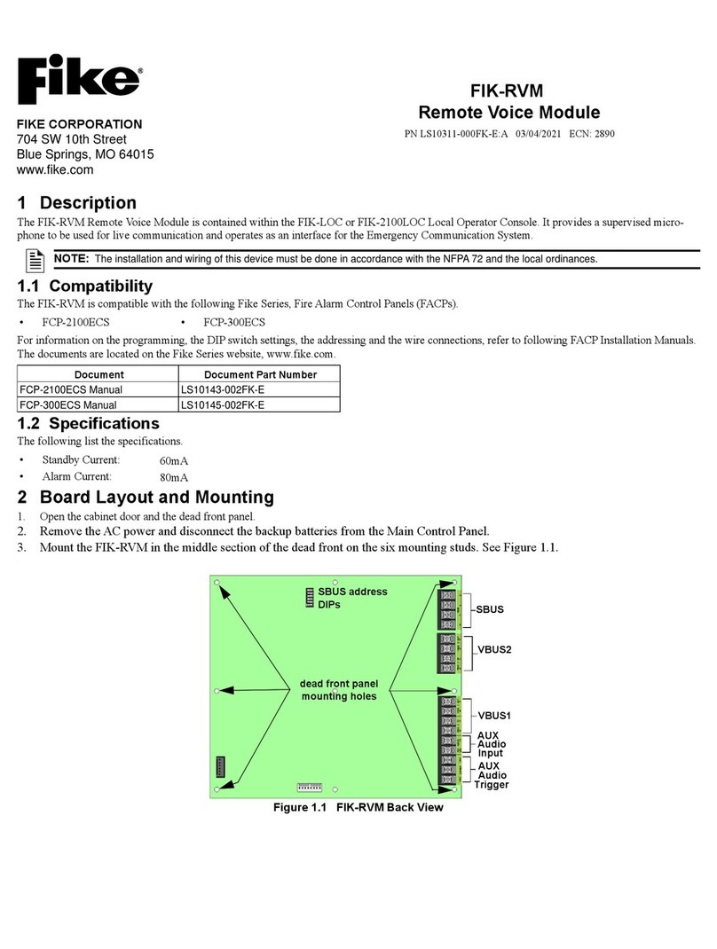
Fike FIK-RVM User manual

Fike
Fike TWINFLEX IRM 100-0011 User manual
Popular Control Unit manuals by other brands

bee
bee 71MS PN 16 Operating and assembly instruction

ABB
ABB ACSM1-204 Quick installation and start-up guide

Epson
Epson GP-C830 user guide
Fisher
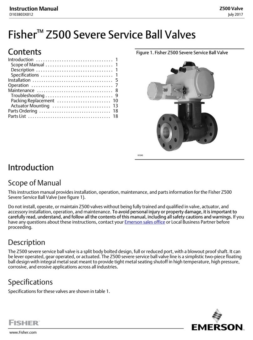
Fisher Z500 instruction manual
Vexve
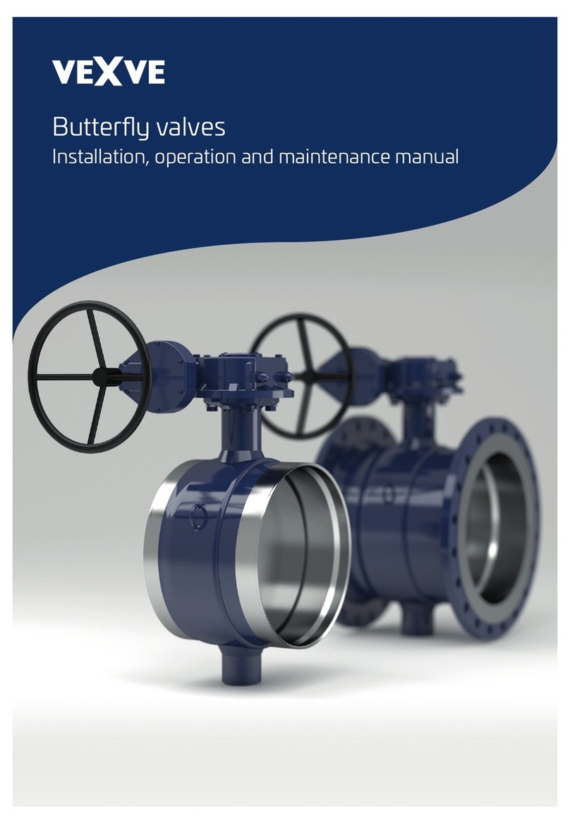
Vexve BFS400W1 Installation, operation and maintenance manual

Dover
Dover OPW Midland A-522-C2-CS-SJ-SU-ST Disassembly instructions
