manuals.online logo
Brands
  1. Home
  2. •
  3. Brands
  4. •
  5. Filtration Group
  6. •
  7. Water Filtration System
  8. •
  9. Filtration Group Pi 150 User manual

Filtration Group Pi 150 User manual

MAHLE Industrialfiltration is now Filtration Group. For more information, visit www.FiltrationGroup.com
Low Pressure Filter
Pi 150
Nominal pressure 10/25 bar (140/360 psi), nominal size up to 630
1. Features
.
High performance filters for modern hydraulic systems
_Provided for pipe installation
Modular system
Compact design
Minimal pressure drop through optimal flow design
Visual/electrical/electronic maintenance indicator
Threaded connections
Quality filters, easy to service
Equipped with highly efficient glass fibre PS filter elements
Beta rated elements according to ISO 16889 multipass test
Elements with high differential pressure stability and dirt holding
capacity
Worldwide distribution
Low Pressure Filter Pi 150 up to NG 630 2
2. Flow rate/pressure drop curve complete filter
y = differential pressure ∆p [bar]
x = flow rate V [l/min]
Low Pressure Filter Pi 150 up to NG 630 3
3. Separation grade characteristics
y = beta-value
x = particle size [µm]
_
determined by multipass tests (ISO 16889)
calibration according to ISO 11171 (NIST)
4. Filter performance data
measured according to ISO 16889 (multipass test)
-
PS elements with max. ∆p 10 bar
Sm-N 2 elements with max. ∆p 5 bar
-
Sm-N 2 β4(C) ≥200
PS 3 β5(C) ≥200
PS 6 β7(C) ≥200
PS 10 β10(C) ≥200
PS 25 β20(C) ≥200
-
values guaranteed up to 10 bar differential pressure, Sm-N 2 ele-
ments up to 5 bar differential pressure
-
The filter element Sm-N 2 is an element with a very large dirt holding
capacity, especially for bypass filtration.
5. Quality assurance
Filtration Group filters and filter elements are produced according to the following international standards:
Norm Designation
DIN ISO 2941 Hydraulic fluid power filter elements; verification of collapse/burst resistance
DIN ISO 2942 Hydraulic fluid power filter elements; verification of fabrication integrity
DIN ISO 2943 Hydraulic fluid power filter elements; verification of material compatibility with fluids
DIN ISO 3723 Hydraulic fluid power filter elements; method for end load test
DIN ISO 3724 Hydraulic fluid power filter elements; verification of flow fatigue characteristics
ISO 3968 Hydraulic fluid power filters; evaluation of pressure drop versus flow characteristics
ISO 10771.1 Fatigue pressure testing of metal containing envelopes in hydraulic fluid applications
ISO 16889 Hydraulic fluid power filters; multipass method for evaluation filtration performance of a filter element
-
6. Symbols
Low Pressure Filter Pi 150 up to NG 630 4
7. Order numbers
Example for ordering filters:
1. Housing design 2. Filter element
V = 400 l/min, bypass, electrical indication,
nominal pressure 10 bar
Type: Pi 1535 / 10-058
Order number: 77774631
PS 10
Type: 852 760 PS 10
Order number: 77774425
7.1 Housing design
Nominal size
NG [l/min] Order
number Type
Nominal
pressure
[bar]
with bypass
valve and
visual
indicator
with bypass
valve and
electrical
indicator
with
visual
indicator
with
electrical
indicator
77774649 Pi 1535/10-057
77774631 Pi 1535/10-058
77804909 Pi 1535/10-068
77804917 Pi 1535/10-069
10
77955982 Pi 1535/25-057
400
77907892 Pi 1535/25-058 25
77774623 Pi 1560/10-057
77774615 Pi 1560/10-058
77804941 Pi 1560/10-068
77804958 Pi 1560/10-069
10
77955990 Pi 1560/25-057
630
77970718 Pi 1560/25-058 25
When filter with non bypass configuration is selected the collapse pressure of the element must not be exceeded.
_
_
7.2 Filter elements*
Nominal size
NG [l/min] Order
number Type Filter material max. ∆p
[bar] Filter surface
[cm²]
77774458 852 760 Mic 5 Mic 5 23800
77774441 852 760 Mic 10 Mic 10 23800
77955859 852 760 Sm-N 2 Sm-N 2
5
16000
77774433 852 760 PS 3 PS 3 14500
78299042 852 760 PS 6 PS 6 14500
77774425 852 760 PS 10 PS 10 14500
400
77806565 852 760 PS 25 PS 25
10
14500
77774417 852 761 Mic 5 Mic 5 47600
77774409 852 761 Mic 10 Mic 10 47600
78375867 852 761 Sm-N 2 Sm-N 2
5
32000
77774391 852 761 PS 3 PS 3 29000
78225898 852 761 PS 6 PS 6 29000
77774383 852 761 PS 10 PS 10 29000
630
77806573 852 761 PS 25 PS 25
10
29000
* a wider range of element types is available on request.
Low Pressure Filter Pi 150 up to NG 630 5
8. Technical specifications
Nominal pressure: 10/25 bar (140/360 psi)
Temperature range: -10 °C to +120 °C
(other temperature ranges on request)
Bypass setting: ∆p 3.5 bar ±10 %
Material filter head/cover: GAL
Material filter housing: St
Sealing material: NBR
Maintenance indicator setting: ∆p 2.2 bar ±10 %
Electrical data of maintenance indicator:
Max. voltage: 250 V AC/200 V DC
Max. current: 1 A
Contact load: 70 W
Type of protection: IP 65 in inserted and
secured status
Contact: normally open/closed
Cable sleave: M20x1.5
The switching function can be changed by turning the electric upper
part by 180° (normally closed contact or normally open contact). The
state on delivery is a normally closed contact. By inductivity in the
direct current circuit the use of suitable protection circuit should be
considered. Further maintenance indicator details and designs are
available in the maintenance indicator data sheet.
We draw attention to the fact that all values indicated are average
values and do not always occur in specific cases of application. Our
products are continually being further developed. Values, dimen-
sions and weights can change as a result of this. Our specialized
department will be pleased to offer you advice.
We recommend you to contact us concerning applications of our fil-
ters in areas governed by the EU Directive 94/9 EC (ATEX 95). The
standard version can be used for liquids based on mineral oil (cor-
responding to the fluids in Group 2 of Directive 97/23 EC Article 9).
If you consider to use other fluids please contact us for additional
support.
Housings with nominal pressure 10 bar (140 psi) are fitted standard
with air bleeder valve, housings with nominal pressure 25 bar (360
psi) with a venting screw.
Subject to technical alteration without prior notice.
9. Dimensions
All dimensions except "C" in mm.
Type A B C D E F
G
10
bar
G
25
bar H I K M N O P S T Weight
[kg]
Pi 1535 78 42 G1½ 643 680 425 190 225 165 225 230 90 44 M12x20 59 - - 17.1
Pi 1560 78 42 SAE 2 1005 1045 850 190 225 165 225 230 90 44 M12x20 59 42.9 77.8 27.1
NPT- and SAE connections on request.
* Standard pressure series hole pattern 3000 PSI
Low Pressure Filter Pi 150 up to NG 630 6
10. Installation, operating and maintenance instructions
10.1 Filter installation
When installing the filter make sure that sufficient space is available
to remove filter element and filter housing.
-
10.2 Connecting the electrical maintenance indicator
The electrical indicator is connected via a 2-pole appliance plug ac-
cording to DlN EN 175301–803 with poles marked 1 and 2. The elec-
trical section can be inverted to change from normally open position
to normally closed position or vice versa.
-
10.3 When should the filter element be replaced?
1 . Filters equipped with visual and electrical maintenance indicat-
or:
During cold starts, the indicator may give a warning signal.
Press the red button of the visual indicator once again only after
operating temperature has been reached. lf the red button im-
mediately pops up again and/or the electrical signal has not
switched off after reaching operating temperature, the filter ele-
ment must be replaced after the end of the shift.
2 . Filters without maintenance indicator:
The filter element should be replaced after the trial run or flush-
ing of the system. Afterwards follow instructions of the manu-
facturer.
3 . Please always ensure that you have original Filtration Group
spare elements in stock: Disposable elements (PS, Sm-N, Mic)
cannot be cleaned.
-
10.4 Element replacement
1 . Stop system and relieve filter from pressure.
2 . Loosenquick-actionclamp(10bar version) or screwsofflanged
cover,remove cover,and opendrain valve.Housing completely
vented.
3 . Remove filter element from the filter housing.
4 . Check seal for damages, replace if necessary.
5 . Make sure that the order number on the spare element corres-
ponds to the order number of the filter name-plate.
Remove the plastic bag and push element over the spigot in the
filter head.
6 . 10 bar version: Close drain valve, relocate cover, and close the
quick-action clamp. Filters are automatically vented via the air
bleeder valve, the protection cap S has to be turned 2 times for
being open.
7 . 25 bar version: Close drain valve, and put the cover plate on
so that the stud bolts go into the holes of the cover plate. Make
sure not to squeeze the O-ring on the bottom side of the cover
plate. Hand-tighten the 8 mounting nuts with spring rings. Then
drawupthenutstightcrosswisewithaturn-screwSW19without
canting the cover plate. Tightening torque for mountings nuts is
50 Nm. After bringing the hydraulic unit to service de-aerate the
filter via vent-screw.
Low Pressure Filter Pi 150 up to NG 630 7
11. Spare parts list
Order numbers for spare parts
Position Type Order number
Seal kit
NBR 77831407
FPM 77831415
EPDM 77831423
Maintenance indicator
Visual PiS 3098/2.2 77669971
Electrical PiS 3097/2.2 77669948
+
Electrical upper part only 77536550
Seal kit for maintenance indicator
PiS 3098/2.2 + PiS 3097/2.2
NBR 77760309
FPM 77760317
EPDM 77760325
Air bleeder valve 70323353
Low Pressure Filter Pi 150 up to NG 630 8
LEER
LEER
LEER
LEER
LEER
LEER
LEER
LEER
LEER
LEER
LEER
LEER
LEER
LEER
LEER
LEER
LEER
LEER
LEER
LEER
LEER
LEER
LEER
LEER
LEER
LEER
LEER
LEER
LEER
LEER
LEER
LEER
LEER
LEER
LEER
LEER
LEER
LEER
LEER
LEER
LEER
LEER
LEER
LEER
LEER
LEER
LEER
LEER
LEER
LEER
LEER
LEER
LEER
Filtration Group GmbH
Schleifbachweg 45
D-74613 Öhringen
Phone +49 7941 6466-0
Fax +49 7941 6466-429
[email protected]
www.filtrationgroup.com
78356305.11/2016
MAHLE Industrialfiltration is now Filtration Group. For more information, visit www.FiltrationGroup.com
Suction Filter
Pi 160
1. Features
-
-
High performance filters for modern hydraulic systems
_Provided for tank mounting
Compact design
Minimal pressure drop through optimal flow design
Visual/electrical/electronic maintenance indicator
Threaded or flanged connections
Vacuum gauge serial production
Quality filters, easy to service
Quick-lock design and shut off valve
Equipped with highly efficient Mic, Sm-x or Drg filter elements
Beta rated elements according to ISO 16889 multipass test
Elements with high differential pressure stability and dirt holding
capacity
Worldwide distribution
LEER
Suction Filter Pi 160 up to NG 315 2
2. Flow rate/pressure drop curve complete filter
y = differential pressure ∆p [bar]
x = flow rate V [l/min]
3. Symbols
Suction Filter Pi 160 up to NG 315 3
4. Order numbers
Example for ordering filters:
1. Housing design 2. Filter element
V=100 l/min, gauge
Type: Pi 1615-366
Order number: 77774813
Sm-x 25
Type: 852 754 Sm-x 25
Order number: 77730195
4.1 Housing design
Nominal size*
NG [l/min]
Sm-x + Mic/Drg Order
number Type with
vacuum gauge
with
vacuum switch
230V
with
vacuum switch
42V
77774854 Pi 1607-166
77774847 Pi 1607-16580/100
77774714 Pi 1607-170
77774839 Pi 1615-166
77774821 Pi 1615-165
77774706 Pi 1615-170
77774813 Pi 1615-366
77774805 Pi 1615-365
77774730 Pi 1615-370
77774797 Pi 1615-466
77774789 Pi 1615-465
100/160
77774722 Pi 1615-470
77874480 Pi 1620-366
77874498 Pi 1620-365160/315
77874506 Pi 1620-370
* at operational viscosity (33 mm²/s); Sm-x 25 (ß20(C) ≥200) and ∆p ≤0,1 bar
4.2 Filter elements
Nominal size
NG [l/min] Order
number Type Filter material Filter surface
[cm²]
77729338 852 753 Mic 10 Mic 10 5700
77729429 852 753 Mic 25 Mic 25 570080
77729577 852 753 Sm-x 25 Sm-x 25 3750
77729387 852 754 Mic 10 Mic 10 15850
77729445 852 754 Mic 25 Mic 25 15850100
77730195 852 754 Sm-x 25 Sm-x 25 10400
77874514 852 821 Mic 10 Mic 10 16750
77874522 852 821 Mic 25 Mic 25 16750160
77874530 852 821 Sm-x 25 Sm-x 25 11000
4.3 Filter elements wire mesh
Nominal size*
NG [l/min] Order
number Type Filter material Filter surface
[cm²]
77862345 852 753 Drg 60 Drg 60 2300
100 77729486 852 753 Drg 100 Drg 100 2300
77862352 852 754 Drg 60 Drg 60 6250
160 77729528 852 754 Drg 100 Drg 100 6250
77874548 852 821 Drg 60 Drg 60 6650
315 77874555 852 821 Drg 100 Drg 100 6650
* at operational viscosity (33 mm²/s) and Drg 100
Suction Filter Pi 160 up to NG 315 4
5. Technical specifications
Design: suction filter for tank mounting
with shut off valve
Installation: horizontally under oil level
or vertically above oil level
with optional extension pipe
Temperature range: -10 °C to +120 °C
(other temperature ranges on request)
Filter head material: GDAL
Filter housing material: St
Sealing material: NBR/AL
Indicating range
vacuum gauge: -1 bar to 1.5 bar
Pressure setting vacuum switch: -200 mbar
Electrical data of vacuum switch (PiS 3070):
Maximum voltage: 230 V~/=
Maximum current on contact: 6 A
Contact: change-over switch
Electrical connections: AMP 6.3 DIN 46248
for bushings according to
DIN 46247
Fitting position: any fitting positions possible
(fitting position has to be defined
when ordering indicators with
defined switch point)
Type of protection: IP 00 - without protecting cap
IP 54 - with protecting cap
Vacuum switch 42 V (HES 2200 BP)
Contact: normally open
Breaking capacity: 42 V/6 W as ohmic resistor
Type of protection: IP 54 – with protecting cap
Electrical connections: AMP 6.3 DIN 46248 for recept-
acle for tabs according to con-
nection method, 2 pole
Connecting plan
1 supply line
2 operating contact
3 normally closed contact
4 adjusting screw
We draw attention to the fact that all values indicated are average
values which do not always occur in specific cases of application.
Our products are continually being further developed. Values, di-
mensions and weights can change as a result of this. Our special-
ized department will be pleased to offer you advice.
-
We recommend to contact us concerning applications of our filters in
areas governed by the EU Directive 94/9 EC (ATEX 95). The stand-
ard version can be used for liquids based on mineral oil (correspond-
ing to the fluids in Group 2 of Directive 97/23 EC Article 9). If you
consider to use other fluids please contact us for additional support.
-
Subject to technical alteration without prior notice.
.
*1 Extension pipe available upon request
*2 Extention height min.
Suction Filter Pi 160 up to NG 315 5
6. Dimensions
Dimension Pi 1607-... Pi 1615-... Pi 1615-... Pi 1615-... Pi 1620-...
O/P 110/64 166 110/64 166 110/64 366 110/64 466 110/64 366
O/P 135/71 165 135/71 165 135/71 365 135/71 465 135/71 365
O/P 130/55 170 130/55 170 130/55 370 130/55 470 130/55 370
Fig. 4 4 2 3 1
A G1½ G2 SAE 2" 2 x G1 SAE 3"
B 56 68 41
C 87 87 87 87 95
D 49 49 53 53 73
E 46 46 50 50 70
F 144 144 144 144 182
G 178 471 471 471 433
H 322 615 615 615 615
I 375 680 680 680 710
J 60
K 77,8 106.4
L 42.9 61.9
M M12 M16
N 50 76
Weight [kg] 2.7 3.5 3.5 3.5 5.0
7. Installation, operating and maintenance instructions
-
7.1 Filter installation
When installing the filter make sure that sufficient space is available
toremovethefilter element and thefilterhousing.Preferably the filter
should be installed with the housing pointing downwards.
The maintenance indicator must be visible.
-
7.2 When should the filter element be replaced or cleaned?
Filters equipped with visual and electrical maintenance indicator:
During cold starts, the indicator may give a warning signal. If vacu-
ummeter shows > 0,2 bar or the electrical signal has not switched
off after reaching operating temperature, the filter element must be
replaced or cleaned after the end of the shift. Please always ensure
that you have original Filtration Group spare elements in stock: Dis-
posable elements (Mic or Sm-x) cannot be cleaned.
7.3 Element replacement
1 . Stop system and relieve filter from pressure.
2 . Unscrew nuts, turn cover counter-clockwise and pull. Unscrew
element from support.
3 . Check O-ring on the filter for damage. Replace, if neccessary.
4 . Make sure that the order number on the spare element corres-
ponds to the order number of the filter name-plate.
5 . Complete installation.
-
7.4 Cleaning methods for cleanable elements
a) Ultrasonic cleaning
Insert the contaminated suction filter element into an ultrasonic bath
for approx. 3 minutes; then rinse in clean liquid. Afterwards, blow air
into the filter from the clean side inward.
-
b) Manual cleaning
1 . Remove coarse external contamination in a separate cleaning
tank using a brush and cleaning agent.
2 . Place filter in unused cleaning liquid (approx. 20 min)
3 . Wash filter with cleaning liquid from the outside to the inside.
4 . Dry element with pressured-air from the clean side to the dirt
side; the cleaning efficiency is about 60–70%
Using either method, be sure that no dirt is entering to the clean side
of filter.
Suction Filter Pi 160 up to NG 315 6
8. Spare parts list
Order numbers for spare parts
Position Type Order number
Vacuum switch 230 V
(PiS 3070/200 mbar) 77669724
Vacuum switch 42 V (HES 2200
BP) 78308892
Pressure gauge
(-1 to 1.5 bar) 76345763
Seal kit for filter housing + filter element
NBR 77874563
FPM 77904840
EPDM 77904857
LEER
LEER
LEER
LEER
LEER
LEER
LEER
LEER
LEER
LEER
LEER
LEER
LEER
Filtration Group GmbH
Schleifbachweg 45
D-74613 Öhringen
Phone +49 7941 6466-0
Fax +49 7941 6466-429
[email protected]
www.filtrationgroup.com
78356396.11/2016
MAHLE Industrialfiltration is now Filtration Group. For more information, visit www.FiltrationGroup.com
Suction Filters
Pi 1710
Nominal size up to 480
1. Features
-
-
Pumps incorporated in hydraulic systems must be protected from
coarse containments which when not removed by any other filtering
devices may gain access to tank.
-
Filtration Group suction filters, series Pi 1710, stand out for their
rugged construction and large filter surface area.
-
The filter surface is dimensioned to ensure long life at the proper
corresponding flow rate.
The installation should be ahead of the pump in the tank for optimal
protection.
-
The standard filter material is a 100 µm stainless steal wire mesh.
_Rugged construction
Large filtering surface area
Worldwide distribution
Suction Filter Pi 1710 up to NG 480 2
2. Flow rates/pressure drop curve
3. Order numbers
3.1 Housing design
Nominal size
NG [l/min] Order number Type Filter surface
[cm²]
10 77661598 Pi 1710/1 104
15 77661606 Pi 1710/2 104
30 77661614 Pi 1710/3 170
50 77661622 Pi 1710/4 394
60 77661697 Pi 1710/51 510
80 77661630 Pi 1710/5 642
120 77661705 Pi 1710/52 940
150 77661648 Pi 1710/6 1104
240 77661655 Pi 1710/7 1484
290 77661689 Pi 1710/71 1858
360 77661663 Pi 1710/8 2738
410 77661713 Pi 1710/81 3434
480 77661671 Pi 1710/9 3422
Suction Filter Pi 1710 up to NG 480 3
4. Technical specifications
Flow capacity: 10 to 480 l/min at 33 mm ²/s
viscosity and 0.1 bar ∆p
Temperature range: -10 °C to +120 °C
Degree of filtration: 100 µm
Other ratings: on request
Material of connecting port + end
cap: PA 6 GF 30
Material of end cap: galvanized steel
Material of inner tube: galvanized steel
Material of wire mesh: stainless steel 1.4301
-
We draw attention to the fact that all values indicated are average
values and do not always occur in specific cases of applications.
Our products are continually being further developed. Values, di-
mensions and weights can change as a result of this. Our special-
ized department will be pleased to offer you advice.
_
We recommend you to contact us concerning applications of our fil-
ters in areas governed by the EU Directive 94/9 EG (ATEX 95).
The standard version can be used for liquids based on mineral oil
(corresponding to the fluids in Group 2 of Directive 97/23 EC Article
9). If you are planning to use other fluids please contact us for addi-
tional support.
_
Subject to technical alteration.
5. Dimensions
All dimensions except "d2" in mm.
Type d1d2h1h2SW Weight
[kg]
Pi 1710/1 46 G¼ 59.5 18 22 0.10
Pi 1710/2 46 G3/8 59.5 18 22 0.10
Pi 1710/3 61 G½ 53.5 13 27 0.14
Pi 1710/4 61 G¾ 86.5 13 32 0.20
Pi 1710/51 87 G1 86.5 21 41 0.32
Pi 1710/5 87 G1 107.5 21 41 0.35
Pi 1710/52 87 G1 152.5 21 41 0.40
Pi 1710/6 99 G1¼ 122 21.5 46 1.00
Pi 1710/7 99 G1½ 159 28 50 1.00
Pi 1710/71 99 G1½ 189 28 50 1.05
Pi 1710/8 131 G2 161 30 65 1.20
Pi 1710/81 131 G2 191 30 65 1.40
Pi 1710/9 131 G2½ 198 37.5 80 1.50
6. Cleaning methods
a) Ultrasonic cleaning
Insert the contaminated suction filter element into an ultrasonic bath for approximately 3 minutes, then rinse in clean liquid. Afterwars, blow
air into the filter from the clean side outward.
The cleaning effect is approximately 80-90 %.
-
b) Manual cleaning
1 . Remove coarse external contamination in a seperate cleaning tank using a brush and cleaning agent.
2 . Place filter in unused cleaning liquid (approximately 20 minutes).
3 . Wash filter with cleaning liquid from the inside to the outside. The cleaning effect is approximately 60-70 %.
-
Using either method be sure that no dirt is washed on the inside of the element.
Suction Filter Pi 1710 up to NG 480 4
LEER
LEER
LEER
LEER
LEER
LEER
LEER
Filtration Group GmbH
Schleifbachweg 45
D-74613 Öhringen
Phone +49 7941 6466-0
Fax +49 7941 6466-429
[email protected]
www.filtrationgroup.com
78357287.12/2016
MAHLE Industrialfiltration is now Filtration Group. For more information, visit www.FiltrationGroup.com
Low Pressure Filter/Suction Filter
Pi 1941
Nominal pressure 10/25 bar (140/360 psi), up to nominal size 63
1. Features
-
_
High performance filters for modern hydraulic systems
_Provided for pipe installation
Modular system
Compact design
Minimal pressure drop through optimal flow design
Visual maintenance indicator
Threaded connections
-
_
_
_Quality filters, easy to service
Equipped with highly efficient glass fibre Sm-x and Mic filter
elements
Beta reated elements according to ISO 16889 multipass test
Elements with high differential pressure stability and dirt holding
capacity
Worldwide distribution
Low Pressure Filter Pi 1941 up to NG 63 2
2. Flow rate/pressure drop curve complete filter
y = differential pressure ∆p [bar]
x = flow rate V [l/min]

Other Filtration Group Water Filtration System manuals

Filtration Group PiW 2175 User manual

Filtration Group

Filtration Group PiW 2175 User manual
Filtration Group Pi 370 Setup guide

Filtration Group

Filtration Group Pi 370 Setup guide
Filtration Group AF 172 G2 User manual
Filtration Group

Filtration Group AF 172 G2 User manual

Filtration Group Pi 210 Series User manual
Filtration Group

Filtration Group Pi 210 Series User manual

Filtration Group R5-3 User manual

Filtration Group

Filtration Group R5-3 User manual
Filtration Group EWH 16 User manual

Filtration Group

Filtration Group EWH 16 User manual

Filtration Group Facet HCS-222-1324 Owner's manual
Filtration Group

Filtration Group Facet HCS-222-1324 Owner's manual

Filtration Group SFK-01 KG User manual
Filtration Group

Filtration Group SFK-01 KG User manual

Filtration Group EG3 User manual

Filtration Group

Filtration Group EG3 User manual
Filtration Group Pi 480 User manual

Filtration Group

Filtration Group Pi 480 User manual

Filtration Group Silent Care User manual

Filtration Group

Filtration Group Silent Care User manual

Filtration Group Pi 21430 User manual

Filtration Group

Filtration Group Pi 21430 User manual

Filtration Group Pi 211 User manual

Filtration Group

Filtration Group Pi 211 User manual

Filtration Group FG Pi 2105 User manual

Filtration Group

Filtration Group FG Pi 2105 User manual

Popular Water Filtration System manuals by other brands
A.O. Smith X8 user guide

A.O. Smith

A.O. Smith X8 user guide

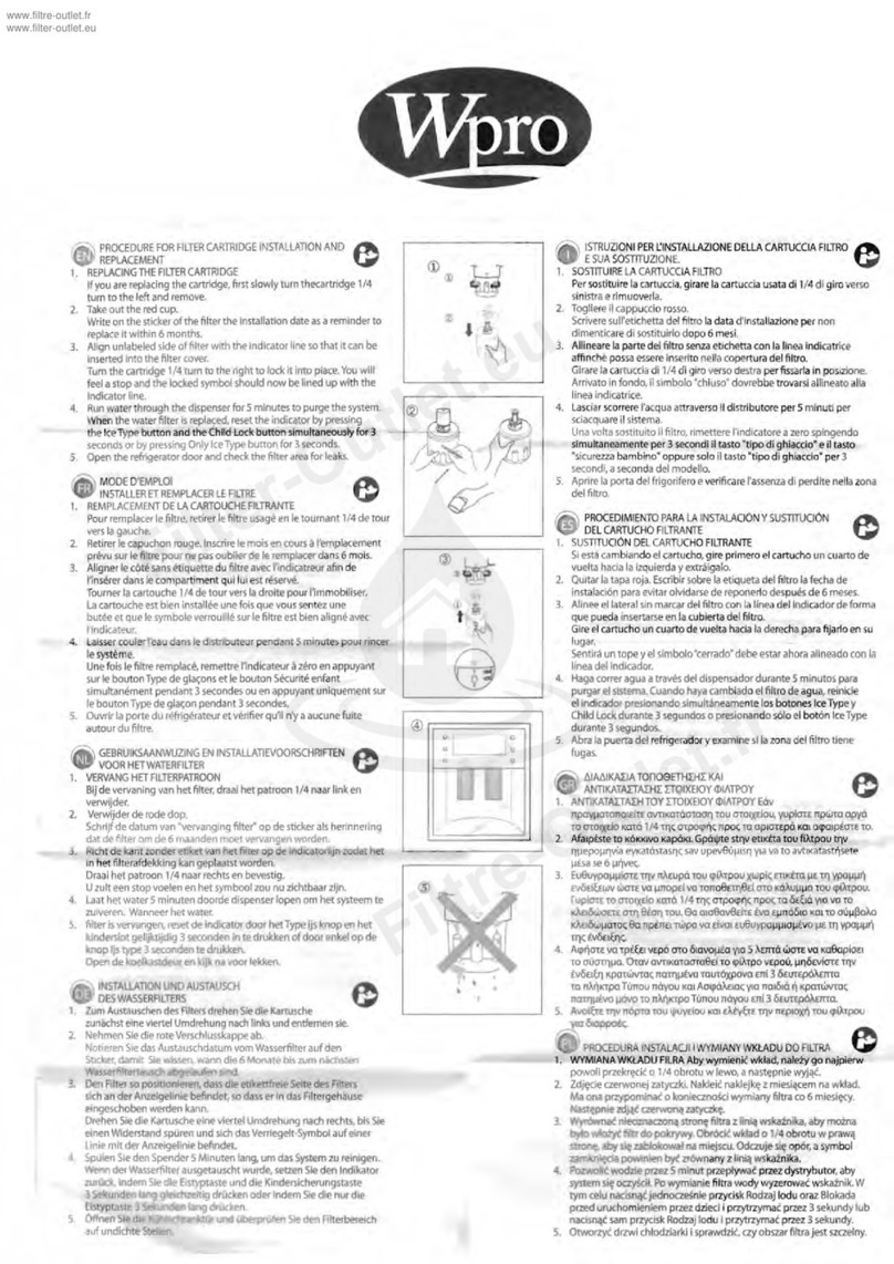
wpro APP100 Procedure for installation and replacement
wpro

wpro APP100 Procedure for installation and replacement

Riello BAG3 MIX BASIC Instructions for the Installaer and for Technical Assistance

Riello

Riello BAG3 MIX BASIC Instructions for the Installaer and for Technical Assistance

Steinbach Speedclean Comfort 50 ORIGINAL OWNER'S MANUAL

Steinbach

Steinbach Speedclean Comfort 50 ORIGINAL OWNER'S MANUAL

HYDAC FILTER SYSTEMS TCU Series Operating and maintenance instructions
HYDAC FILTER SYSTEMS

HYDAC FILTER SYSTEMS TCU Series Operating and maintenance instructions

Pentair FLECK 2815 Service manual

Pentair

Pentair FLECK 2815 Service manual
AQUAMAXX CTECH T-2 manual

AQUAMAXX

AQUAMAXX CTECH T-2 manual

Premier CT-1 Installation, operation and maintenance manual

Premier

Premier CT-1 Installation, operation and maintenance manual

Hagen Fluval 1 Plus manual

Hagen

Hagen Fluval 1 Plus manual

Argo-Hytos FA 008 operating manual

Argo-Hytos

Argo-Hytos FA 008 operating manual

Bluewater CLEONE Complete user's manual

Bluewater

Bluewater CLEONE Complete user's manual

Waterdrop WD-PT-04-42 owner's manual

Waterdrop

Waterdrop WD-PT-04-42 owner's manual

Vetus NSF16S installation instructions
Vetus

Vetus NSF16S installation instructions

Hidrotermal Filtration Combo Series user manual
Hidrotermal

Hidrotermal Filtration Combo Series user manual

Axeon Hydrogen user manual

Axeon

Axeon Hydrogen user manual
Leader Evaporator Springtech EXTREME 6 manual
Leader Evaporator

Leader Evaporator Springtech EXTREME 6 manual

Culligan IC-1000 Installation and operating instructions
Culligan

Culligan IC-1000 Installation and operating instructions

Nature Pure Ultrafine Faucet Series installation instructions

Nature Pure

Nature Pure Ultrafine Faucet Series installation instructions
manuals.online logo
manuals.online logoBrands
  • About & Mission
  • Contact us
  • Privacy Policy
  • Terms and Conditions

Copyright 2025 Manuals.Online. All Rights Reserved.