Fire Pro FPC-2 User manual

Fire Control Panel
FP-C2
Rev 7.0
Page | 1
Operation and Maintenance Manual
Table of Contents
1. Introduction .......................................................................................... 2
2. Operation ............................................................................................. 2
3. Panel Operation .................................................................................... 2
4. Installation and Mounting ...................................................................... 3
5. Installation of FirePro Generators ........................................................... 5
6. Connecting to Master Fire Panel ............................................................. 6
7. Maintenance ......................................................................................... 7
8. Commissioning & Testing ....................................................................... 8
9. Specifications ........................................................................................ 8

Fire Control Panel
FP-C2
Rev 7.0
Page | 2
1. Introduction
The FPC-2, a fire alarm control panel with Extinguishant Control Unit and Aerosol Agent Controller, is designed to comply
with AS4487(2013) - Control and Indicating Equipment. The control equipment is a combined fire alarm control panel
and extinguishant system with one detection zones, and one extinguishant zone.
The FPC-2 Panel Protection Controller enables monitoring of detection and extinguishing circuits. The panel will support
up to 4 FirePro aerosol generators. The FPC-2 requires a battery backed 24V DC power supply capable of delivering
3A for a short period in order to operate the Aerosol Generators. Volt free contacts are available to signal fire and fault
conditions to plant or other monitoring equipment. Jumper links allow a signal to an addressable input module via a
simple, 2 wire connection.
An Isolate Key switch - located on the front of control panel –allows for the isolation the four extinguishant outputs for
service or maintenance purposes.
2. Operation
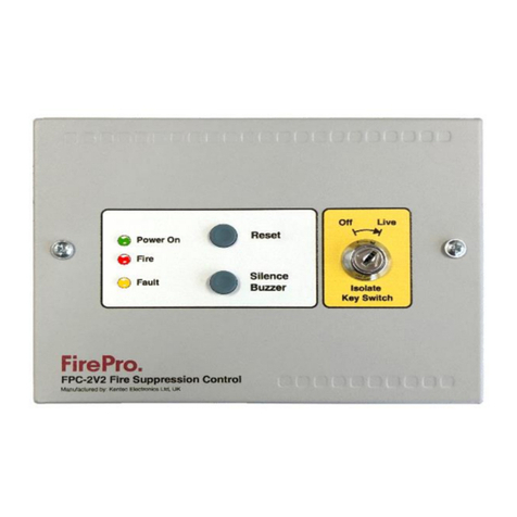
Under normal circumstances, the green Power On indicator will be lit, and the internal buzzer will be silent.
The wiring to the detection circuit and to the FirePro Aerosol Generators is supervised and disconnection of any of this
wiring will be shown by illumination of the yellow Fault indicator on the front panel and operation of the internal buzzer.
The internal fault volt free contact will operate and signal any external equipment that is connected to the controller
Internal indicators are provided to show whether it is the detection circuit wiring or the wiring to the Aerosol Generators
that has a fault.
The buzzer may be silenced by pressing the Buzzer Silence button.
Upon activation of a linear heat detection cable or smoke detector, the red Fire indicator will be lit, the FirePro Aerosol
Generators will operate and immediately discharge extinguishing Aerosol into the protected area, the internal buzzer will
sound and the Fault indicator will illuminate, indicating that the Aerosol Generators have fired and need replacing.
The internal fire volt free contact will operate and signal any external equipment that is connected to the controller. The
buzzer may be silenced by pressing the Buzzer Silence button. Following a fire activation and replacement of the FirePro
Aerosol Generators the system can be returned to normal operation by operating the Reset button on the front of the
controller.
Operating the Isolate key-switch by turning the key anti-clockwise from ‘Live’ to ‘Off’ isolates the four extinguishant
outputs thereby preventing discharge. This mode should only be used for service, maintenance, or temporary purposes -
In the ‘Off’ position and where the detection circuit is activated, extinguishant outputs will not operate.
With the Isolate key-switch in the ‘Off’ position and where the detection circuit is activated, the internal volt free contact
will continue to operate (change over). The Reset and Buzzer Silence buttons will continue to be operational, when
pressed.
Note: The controller will continue to show a fault condition until the Aerosol Generators are replaced.
3. Panel Operation
Silence Alarms
The
Silence/Sound alarm
button will only silence the buzzer in the FPC-2 unit.
Reset
To
Reset
button is a full reset on the FPC-2 panel only.
Indications
Power Indicator Operates as long as voltage is coming into panel –range is 12-30vDC.
Fault Indicator Operates whenever any circuit fault is detected in the system. It is a common indictor for both the
activation and detection circuits. The fault indication will operate when the system is isolated.
Fire Indicator Operates when the detection circuit goes into alarm.

Fire Control Panel
FP-C2
Rev 7.0
Page | 3
4. Installation and Mounting
This equipment is designed to be operated from 24V DC supply. This power
supply must be battery backed.
The FPC-2 should be effectively bonded to earth. Failure to ensure that all
conductive accessible parts of this equipment are adequately bonded to
earth will render the equipment unsafe.
This control panel is designed for indoor use only and at temperatures
between -50C (+/- 3) and +400C (+/-2) and with a maximum relative
humidity of 95%. Panels is rated to IP30 and suitable for mounting indoors.
Operation outside of these limits may render the equipment unsafe.
MOUNTING –Panel must be securely mounted.
Cables should be connected using cable glands fitted to the knockouts.
DIMENSIONS - 200H x 150W x 50D mm
Connecting to the circuit board
All connections for field wiring are to a
single row of terminals along the top of the
circuit board.
Cabling must comply with the Australian
Standards. The resistance of any cable
must not exceed 25 ohms.
Terminals are capable of accepting wires of
up to 2.5mm2.
Power 24v IN –24v OUT
The polarity of these terminals is very important. The 24V IN is for connection of the power from a previous unit or a
power supply and the 24V OUT is for connection to further units.
Max Number of FPC-2 Units chained together is 3 using the power IN / OUT link. For additional units need to wire
separately. Power supply will need to consider what current is required to ensure all devices operate correctly.
Connection of Aerosol Units to Activation circuit
These terminals are for the connection of FirePro® Aerosol
Generators. Test lamps are provided in the terminals to allow
testing of the system before connecting the FirePro®
generators. These test lamps should be removed from the
terminals if a FirePro® Aerosol Generator is to be fitted.
Any FirePro® generator outputs that are not being used
should be left with test lamps fitted.

Fire Control Panel
FP-C2
Rev 7.0
Page | 4
Detection zone wiring
These terminals are for the connection of a conventional type 24V smoke
detectors or linear heat detection cable.
The wiring is monitored for open circuit faults.
The 6K8 end of line resistor are factory fitted to the control panel’s terminals
must be removed and placed across the last device that is wired to the
circuit.
Detection circuit must be wired as a single, radial circuit with no spurs or T
junctions to enable the monitoring circuit to work correctly.
Convention detectors may be mixed Thermal and Smoke.
A short circuit will create an ALARM condition.
Sounder circuit wiring
There is no dedicated Siren circuit on this panel. Using the
Fire Relay, a siren can be connected.
The “FIRE” terminal on the FPC2 is a relay that creates a
closed circuit upon activation of the panel.
This can be used to activate a siren or other device.
Cabling Requirements
Cable Requirements - All cabling in the FirePro Installation MUST
be done using 0.75mm shielded Fire Rated Cable. Care taken to
ensure that all cables are isolated, and that RF shielding on cable
is stripped back to ensure that there is not accidental grounding.
Cables are colour coded for easy identification.
Extension Leads - Deutsch Plugs must be used to ensure water-
proof connections are made throughout the installation.
Fault relay
The Fault Relay
is normally energised and will de-energise upon any fault condition including total loss of power. Volt
free changeover contact that will operate whenever there is a fault condition. This contact is rated for a
maximum of 30V DC and 1Amp. These ratings must not be exceeded
Fire relay
The Fire Relay will energise upon activation of a fire condition. The relay will remain activated until the control panel is
reset. Volt free changeover contact that will operate whenever the system is triggered to alarm. This contact is rated
for a maximum of 30V DC and 1Amp. These ratings must not be exceeded.

Fire Control Panel
FP-C2
Rev 7.0
Page | 5
5. Installation of FirePro Generators
FirePro Condensed Aerosol Fire Extinguishing System Arrangement.
FirePro units and system components installed to allow inspection and maintenance.
Locate FirePro units where they are not exposed to mechanical damage, exposed to chemicals, or weather
conditions, that may render them inoperative. Protective provisions shall be adopted, if necessary.
FirePro units shall be securely installed. Use heavy duty brackets where necessary. Brackets should be capable
of handling the risk environment, including vibration.
FirePro units must be installed at NOT less than the minimum safe distances as
specified in the design calculations.
Means for prompt rescue of any trapped personnel shall be provided, including:
Adequate aisle ways/routes of exit.
Alarms –audible and visual, that operate immediately on detection of the fire.
Signs in accordance with relevant standards for the installation.
System components shall be positioned to the minimum clearances from
energized electrical parts as per: AS 4487 and AS 3000.
Handling and Storage - when handling the Condensed Aerosol Generators do
not:
•Disassemble the unit
•Carry out any welding work in the vicinity of the fire
extinguishing system components.
•Exert force or impact which creates physical or
mechanical damage to the casing.
STORAGE and OPERATIONAL CONDITIONS
•Temperature: –54 and +54°C
•Humidity: maximum 98% RH
•Service life: 15 years (date of manufacture appears on each generator)
Positioning
CORRECT
FP Units directing the aerosol stream away from opening
INCORRECT
FP units are directing the stream towards the opening.

Fire Control Panel
FP-C2
Rev 7.0
Page | 6
6. Connecting to Master Fire Panel
General
To connect to a Master Indicator Panel, there is some connections to be made between the panels and then some
programming configuration in the Master Panel.
FPC-2 as a sub-panel with stand-alone detection and activation
Following explains connection and configuration to Sigma XT
Master Panel. The concepts will be similar to other
brands/types on master panel.
The connections are 24vDC power which can come from
Sigma XT –or an appropriate external source, and a Single
detection Zone is require on Sigma to allow inputs from FPC-
2.
The EOL Resistor ensures that this circuit is monitored from
the Sigma XT panel.
Once the connections are complete. The Sigma XT panel
must be programmed correctly to set up the FP-C2 as a
remote device. This must be done so that FP-C2 is not treated
as a regular detection device. When programmed correctly,
the FP-C2 will alert the main Sigma XT panel of any alarm or
fault states.
On the Sigma XT FIP, enter Access Level 2 by turning the key in
“Enable Control” port on the Detection card (top card) or by
releasing the read switch by opening the inner Perspex door.
1. Move the “Write Enable” switch to the right on the
Detection Card (top card). The “System Mode” LCD
display will read “00”.
2. The FIP’s detection options are numbered. Using the
controls on the Detection Card, navigate the “System
Mode” LCD display reads “7#”. To do this press the
“Mode (+10)” button until the first number is “7” and
then press the “Select (+1)” button until the display shows the correct detection circuit.
3. The detection circuit number will have a flashing dot next to the
number, indicating that it is programmed for conventional detection.
Press the “Enter” button to change the detection circuit to S/C mode.
This will cause the flashing dot to turn off.
4. Moving the “Write Enable” switch to the left.
Thermal Fuse Connection
A Thermal Fuse to be connected to the ONE of the FirePro Aerosol
Generators in the activation circuit.
The Thermal Fuse allows notification to a control panel that a FirePro
unit has activated. It should be installed in accordance with the
instructions included in the relevant FirePro document.
Menu setting in the XT card allows for a
normally closed (inverted) input to be used.
Connect Thermal Fuse to
Rel.P Switch on Sigmat XT Panel

Fire Control Panel
FP-C2
Rev 7.0
Page | 7
Power Connection from Sigma XT
When FP-C2 is used as a sub-panel from a Sigma XT Control panel it should be connected to a separate Detection Zone
as described earlier. Power can be taken from the Sigma panel as shown.
Power can come from 1, 2 , or 3.
CANNOT USE - AUX 24v from Exting Module as it is current limited to 100mA,
Power from main panel will provide battery backup.
FPC-2 as activation Module only
This configuration uses the FPC-2 as an activation module only. This can be established with any style of AS Panel.
Individual configurations will be dependent on the specifics of the master panel.
Connection will be required for the Power Supply. The activation device needs to
connect to the detection circuit on the FPC-2, this needs to meet the detection circuit
criteria. Once the FPC-2 receives a detection advice –activation of the extinguishant
system is immediate.
Fire and Fault reporting will require connection back to the master panel.
To make the FPC-2 compatible with an addressable input module, move jumpers
J1 and J2 from their default positions (position A) to position B. The FIRE NO and C
terminals can now be connected directly to the addressable input module.
Alarm and fault conditions will be indicated on a addressable fire alarm control panel.
Note: The volt free contact function is not available when the contacts are being
used to signal and addressable input module.
7. Maintenance
FPC-2 control panels do not require any specific maintenance, but should the control panel become dirty it can be wiped
over with a damp cloth and should then be dried with a dry, lint free cloth. Detergents or solvents should not be used to
clean the panel and care must be taken that water does not
Enter
the enclosure.
Testing of the extinguishant system should only be carried out by trained personnel and must be done with appropriate
isolation measures in place to ensure that accidental discharge of the extinguishant agent is avoided and any malfunction
should be reported to the fire alarm maintenance company immediately.

Fire Control Panel
FP-C2
Rev 7.0
Page | 8
8. Commissioning & Testing
ISOLATE SYSTEM
Turn Key-Switch to “Off”
Requires 003 Key
This will create a fault on the Panel.
OPERATIONAL
ISOLATED
TO TEST SYSTEM:
1Isolate system –t urn Key-Switch to “Off”.
2Turn Power off.
3Disconnect FirePro units and connect test lamps or Test
Modules.
4Visually inspect each FirePro unit installed and ensure Bracket
and mounting bolts are secure. The FirePro® unit must be
clean and free of debris.
5Inspect all other component detectors, sirens etc. Inspect cable
for any signs of damage.
6Turn power on to panel and turn to “live”test detection system
to simulate activation-all test lamps to be lit.
7Turn off power Isolate system –Reconnect all FirePro units.
8Turn Power on - Turn system back to Live.
If connecting FP-08800 Test Simulator –Then MUST USE V4 of the
test simulator, or the fuse will blow on EACH test.
Note: If the system has been activated the system activation fuse needs to be inspected as blown fuse
will show as a fault. The Fuse is 1.6AMP Quick Blow.
9. Specifications
Mains supply
24V DC +10% - 15%
Mains supply fuse
1.6Amp (Quick Blow)
Operating Voltage
19-30V DC
Output voltage
19-30V DC +/- 2%
Standby Current
18mA
Extinguishant release output
19 to 30V DC. Fused at 1.6 Amp
Low Voltage limit
6V DC –at this point unit is operational will send fault signal to Sigma XT Panel
Extinguishant release
Immediate –Max 4 FirePro Aerosol units
Extinguishant release duration
Latched - Continuous
Detection Type
Hochiki Conventional PE smoke or Thermal Detectors –Max of 2 Detectors, can be mixed.
Linear Heat Detection Cable - Latching Type NO –LHD Cable Max 30m
Detection Circuit End of Line
6K8 5% ½ Watt resistor
Fault relay contact rating
30VDC 1A Amp max
Fire relay contact rating
30VDC 1A Amp max
Cable Entries
8 x21mm knockouts provided
Terminal capacity
0.5mm2to 2.5mm2 solid or stranded wire
Construction
1.2mm steel –Epoxy Powder Coated
Other manuals for FPC-2
3
Table of contents
Other Fire Pro Control Panel manuals
Fire Pro
Fire Pro 08100 User manual
Fire Pro
Fire Pro FPC-2 User manual
Fire Pro
Fire Pro FP-08450 User manual
Fire Pro
Fire Pro FPC-2 User manual

Fire Pro
Fire Pro FP-22408 User manual
Fire Pro
Fire Pro FPX103C User manual
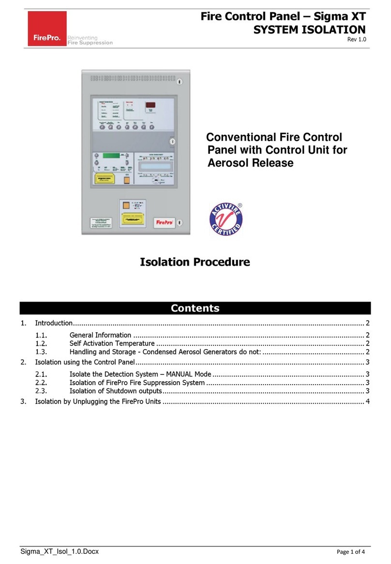
Fire Pro
Fire Pro Sigma XT Reference guide

Fire Pro
Fire Pro 08451 User manual
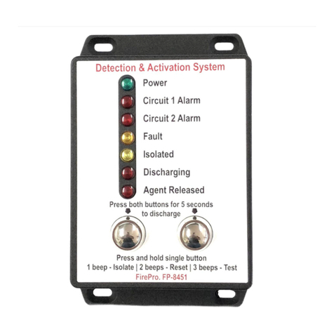
Fire Pro
Fire Pro 08451 User manual
Popular Control Panel manuals by other brands
Kramer
Kramer RC-712M user manual

Well SEC
Well SEC WL1014 user manual
emmeti
emmeti FEBOS - CRONO IMX Basic / WiFi Installation and use manual
dadco
dadco 90.406.421 instruction manual

Visonic
Visonic PowerMaster-33 G2 Installer's guide
Procopi
Procopi SWIMLINE CFB Series Instructions for installation and use
