6
halfway through. Swivel flanges are available (#60-302 for UV1, UV2 Scanners, #60-1664-3, -4 for
45UV5). The sight pipe must permit an unobstructed view of the pilot and/or main flame, and both
pilot and main flames must completely cover the scanner field of view.
Note:
Since oil and gas flames radiate more ultraviolet energy from the base of the flame than from
further out in the flame this fact should be evaluated when installing the scanner sight pipe.
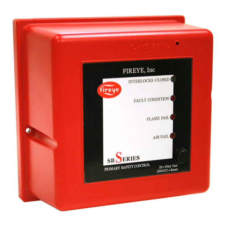
5. CAUTION: The scanner must not sight the ignition spark directly, or any part of the
burner that can reflect the spark back to the scanner. The scanner must not see a pilot
flame that is too small to reliably ignite the main flame.
6. Smoke or unburned combustion gases absorb ultraviolet energy. On installations with negative
pressure combustion chambers, a small hole drilled in the UV1, UV2 sight pipe will help to keep
the pipe clean and free from smoke. The 45UV5 has a
3
/
8
″
plug in the mounting flange that can be
removed. For positive pressure furnaces, provide clean air to pressurize the sight pipe, if necessary.
7. Two UV1, UV2, or 45UV3 scanners may be installed on the burner if it is necessary to view two
areas to obtain reliable detection of the flame. They should be wired in parallel. Only one repeti-
tive self-checking 45UV5 Scanner may be installed on a burner.
8. To increase scanner sensitivity with UV1, UV2 Scanners, a quartz lens permits location of the
scanner at twice the normal distance. Use
1
/
2
″
x 1
1
/
2
″
pipe nipple between UV1 Scanner and the
coupling. Use
3
/
8
″
x close
pipe nipple and a
1
/
2
″
x
3
/
8
″
bushing on UV2 installations.
9. Request the assistance of any Fireye field office for recommendations of a proper scanner instal-
lation on a non-standard application.
Wiring — UV Scanners
To connect the scanner to the control, the UV1 Scanner is supplied with 36
″
(900mm) or 72
″(1800
mm)
of flexible cable. The UV2 is supplied with 36" (900mm) of flexible cable.
45UV5 120 VAC and 230 VAC Models
CAUTION: Be sure to check that proper line voltage is matched to L1 and L2. Applying 230
VAC to models 45UV5-1008 and 45UV5-1009 will damage scanner. 120 VAC applied to model
45UV5-1007 will not operate scanner.
The 45UV5 is supplied with four 72" (1800mm) lead wires. Install them in a suitable length of flexible
armor cable and connect it to the control. A conduit connector is supplied with the scanner. Connect
black wires (shutter) to terminals L1, L2; red wires (UV tube) to terminals S1, S2.
If it is necessary to extend the scanner wiring, the following instructions apply:
Scanner wires should be installed in a separate conduit. The wires from several scanners may be
installed in a common conduit.
1.
Selection of Wire
a. Use #14, 16 or 18 wire with 75
°
C, 600 volt insulation for up to 100 (30.5M) foot distances
(signal loss approximately 20% at 100 feet [30.5M]).
b.
ExtendedScannerWiring:
Forextendedscannerwiringupto500(152M)feet,andforshorter
lengths to reduce signal loss, use a shielded wire (Belden 8254-RG-62/U coaxial cable, or
equal)
foreach scanner wire
of UV1, UV2 and
eachred wire
of the 45UV5. The ends of the
shielding must be taped and not grounded.
c. Asbestos insulated wire should be avoided.
SCANNER MUST HAVE UNOBSTRUCTED
VIEW OF FLAME
NOT THIS NOT THIS BUT THIS
FLAME MUST COMPLETELY COVER
SIGHT OPENING
NOT THIS NOT THIS BUT THIS


