Firmtech FB100AS-F User manual

FB100AS-F User Guide Version 1.0
Revision History
Page 2 / 30
Revision History
Revision
Date
Change Descriptions
Ver 1.0
01-04-2009
- Write a draft

FB100AS-F User Guide Version 1.0
(C) Copyright FIRMTECH Co., Ltd. 2005
Page 3 / 30
(C) Copyright FIRMTECH Co., Ltd. 2005
All rights reserved
The products and operation descriptions are protected by copyright law.
Any part of products and operation description shall not be copied, reproduced,
translated,nor transformed into readable form by electronic device or machines, without
prior consent in writing by FIRMTECH Co., Ltd.
There might be some misprinting or technical faults in the products and operation
description which are subject to change without prior notice.

FB100AS-F User Guide Version 1.0
List of Content
Page 4 / 30
List of Content
1 What is Bluetooth? ............................................................................................................................................................5
1.1 Features of Bluetooth..........................................................................................................................................5
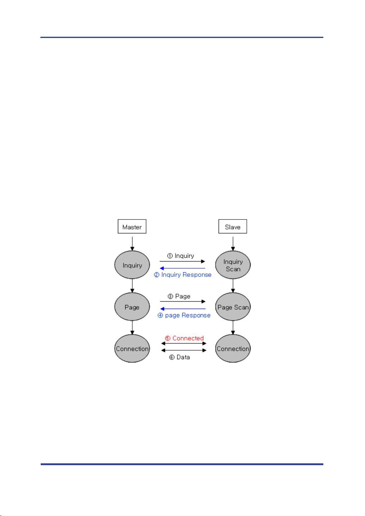
1.2 Operation of Bluetooth......................................................................................................................................5
2 Products Overview.............................................................................................................................................................6
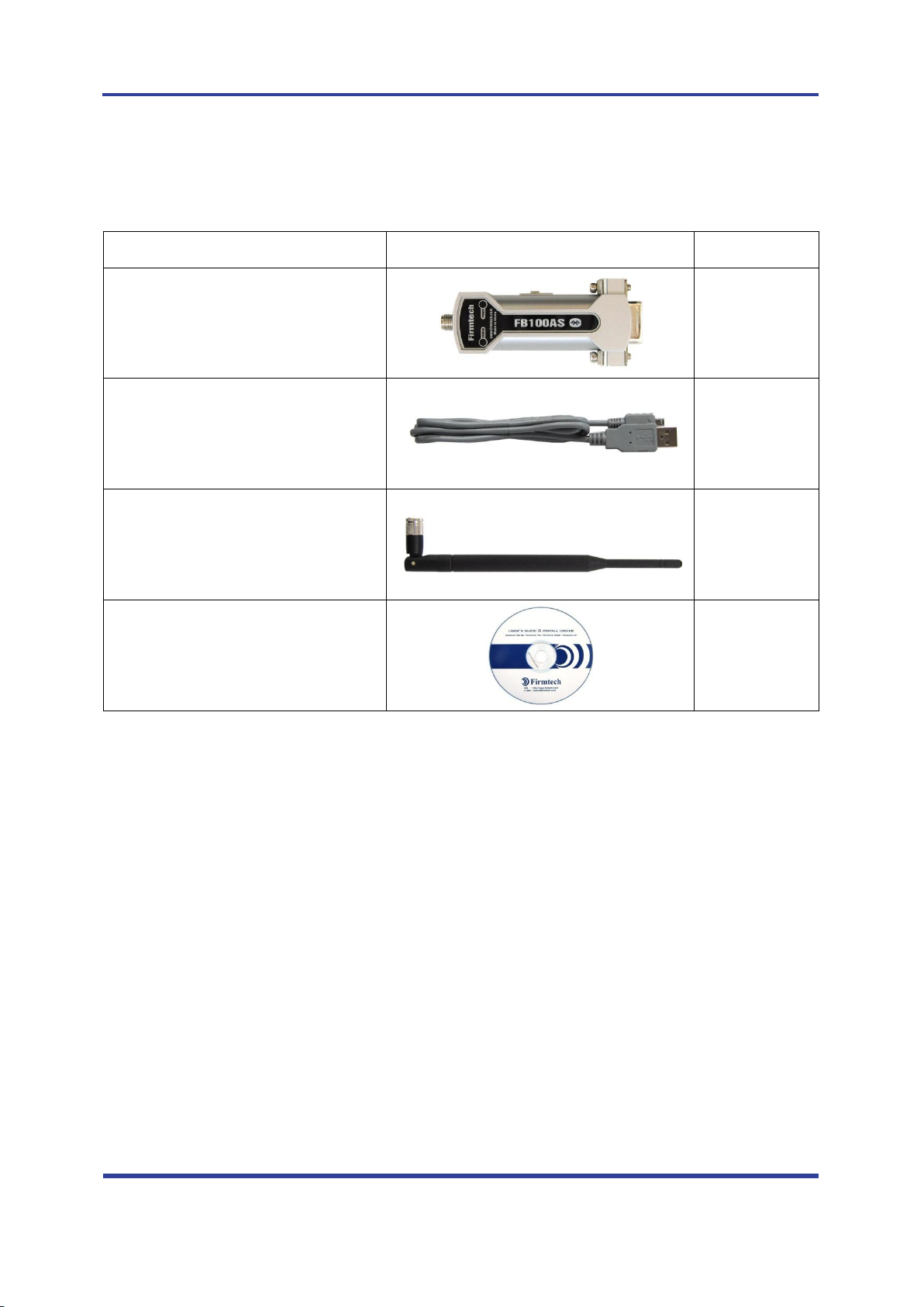
3 PRODUCT COMPONENTS ..............................................................................................................................................7
3.1 Basic Components of FB100AS-F..................................................................................................................7
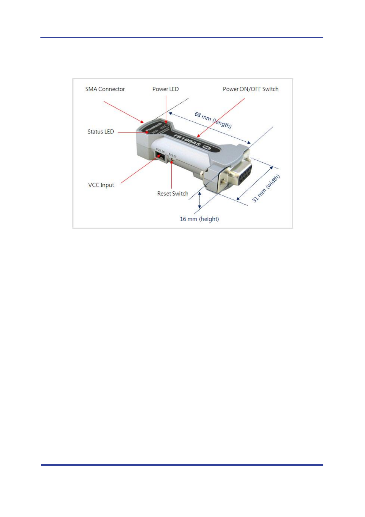
4 Product Appearance .........................................................................................................................................................8
5 Interface ..................................................................................................................................................................................9
5.1 FB100AS-F Interface.............................................................................................................................................9
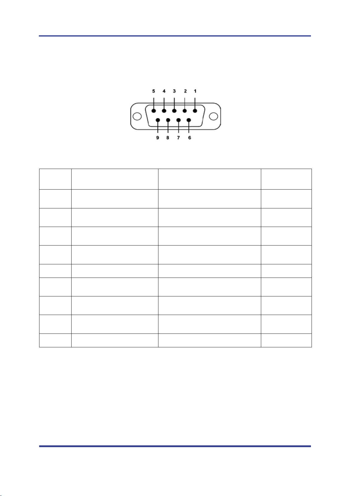
5.2 Pin Connection..................................................................................................................................................... 10
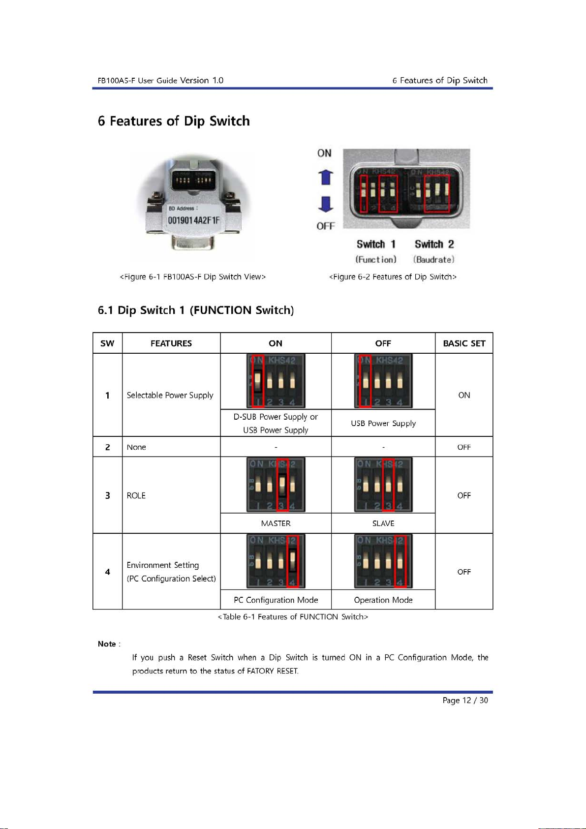
6 Features of Dip Switch.................................................................................................................................................. 12
6.1 Dip Switch 1 (FUNCTION Switch) .............................................................................................................. 12
6.2 Dip Switch 2 (Baud Rate Switch)................................................................................................................ 13
6.3 Initial Set Value of Dip Switch ..................................................................................................................... 13
7 Power Indicator LED / Status LED .......................................................................................................................... 14
8 Performance of Product .............................................................................................................................................. 15
9 Current Consumption.................................................................................................................................................... 16
10 Initial Set Value of Products ................................................................................................................................... 17
11 Connecting the wireless section of Bluetooth .............................................................................................. 18
11.1 Connecting with Connection WIZARD ................................................................................................. 18
11.2 How to connect with Dip Switch Set-up............................................................................................. 21
12 How to complete PC Configuration? ................................................................................................................. 22
12.1 PC Configuration using BTConfig tool ................................................................................................. 22
12.2 PC Configuration using Serial Communication (Hyper Terminal) Program ..................... 25
13 Approval Information................................................................................................................................................. 30
13.1 KCC........................................................................................................................................................................... 30
13.2 FCC compliance Information...................................................................................................................... 30
13.3 CE.............................................................................................................................................................................. 30
13.4 TELEC ...................................................................................................................................................................... 30
13.5 SIG............................................................................................................................................................................ 30

FB100AS-F User Guide Version 1.0
1What is Bluetooth?
Page 5 / 30
1 What is Bluetooth?
1.1 Features of Bluetooth
Objectives of Bluetooth : To Realize Wireless Communication for Short Distance with Low Power
Consumption, High Reliability, and Low Cost.
Frequency in Use: To Use ISM(Industrial, Scientific, Medical) Band which does not require any
permission to use.
-2.400 –2.4835 GHz, 79 channels
-2.465 –2.4835 GHz, 23 channels (in France)
Transmission Rate : 1Mbps ~ 3Mbps
Transmission Output : 1mW (10m, Class2), 100mW (100m Class1)
Network Configuration : Configured with Master and Slave relation. A Bluetooth unit shall allow
simultaneous connections up to 7 devices (in case of ACL).
Reliability : To Guarantee stable wireless communication even under severe noisy environment
through adopting the technique of FHSS (Frequency Hopping Spread Spectrum).
1.2 Operation of Bluetooth
<Feature 1-1 Bluetooth Operation>
Bluetooth operates based on the connection between “Master”and “Slave”.
Masters are simply supposed to do “Inquiry”and “Page”. Slaves are supposed to do “Inquiry Scan”
and “Page Scan”.
If a Master finds a Slave and so “inquiry”is successful, a Slave responds to the Master with its
information.
Interconnection between the Master and the Slave is achieved only if the information from the
Slave is corresponded with the Master, and the Slave sends data to the Master.

FB100AS-F User Guide Version 1.0
2Products Overview
Page 6 / 30
2 Products Overview
FB100AS-F has been developed to replace the previous RS232 Cable system with wireless communication
system to use.
Major Features of FB100AS-F
1. Bluetooth Specification 2.0 Support
2. Bluetooth Piconets (Point to Multipoint) are configurable up to (max. 1:7).
3. Easy to control communication speed by using DIP Switch. (2400 bps –230400bps)
4. Support AT Command, and capable to control FB100AS-F by using AT Command.
5. Easy to connect to use with Bluetooth PDA, Bluetooth USB Dongle, etc.
6. Selectable Power Supply between D-Sub 9 pin Connector and USB Connector
7. Stable Data Transmission / Receipt
8. Simply support the function of Bluetooth Firmware Update
※We request the new users of FB100AS-F to read the information on this description carefully before
they start to use the products.

FB100AS-F User Guide Version 1.0
3PRODUCT COMPONENTS
Page 7 / 30
3 PRODUCT COMPONENTS
3.1 Basic Components of FB100AS-F
MODEL
PICTURE
Q’TY (EA)
FB100AS-F
(RS-232 Serial Adapter)
1
FCA100UC
(USB Power Cable)
1
FCA004DA
(4.dBi Dipole Antenna)
1
CD
(Operation Manual and Test Program)
1
<Table 3-1 Basic Components of FB100AS-F>
※If you find any of above components is defective, or not included in the package, please contact the
seller you purchased.

FB100AS-F User Guide Version 1.0
4Product Appearance
Page 8 / 30
4 Product Appearance
<Figure 4-1 Details and Dimension of FB100AS-F>

FB100AS-F User Guide Version 1.0
5Interface
Page 9 / 30
5 Interface
5.1 FB100AS-F Interface
<Figure 5-1 D-SUB 9 Pin Connector>
PIN NO.
NAME OF SIGNAL
FUNTION
INPUT/OUTPUT
DIRECTION
1
CONNECT_CHECK
DCD
1:N - Connect Check
1:1 - Data Carrier Detect
Output
2
TX
Transfer Data
Data output
Output
3
RX
Received Data
Data Input
Input
4
STREAM_CONTROL
DSR
1:N - Stream Control
1:1 - Data Set Ready
Input
5
GND
Ground
6
STREAM_STATUS
DTR
1:N - Stream Status
1:1 - Data Terminal Ready
Output
7
MESSAGE_CONTROL
CTS
1:N - Message Control
1:1 - Clear To Send
Input
8
MESSAGE_STATUS
RTS
1:N - Message Status
1:1 - UART Ready To Send
Output
9
VCC
Power (DC 4 ~ 12V)
Input
<Table 5-1 Features of D-SUB 9 Signals>
※The power can be supplied through pin number 9.

FB100AS-F User Guide Version 1.0
5Interface
Page 10 / 30
5.2 Pin Connection
5.2.1 Connection Diagram with Flow Control
<Figure 5-2 FB100AS-F Connection Diagram with Flow Control>
5.2.2 Connection Diagram without Flow Control
<Figure 5-3 FB100AS-F Connection Diagram without Flow Control>

FB100AS-F User Guide Version 1.0
5Interface
Page 11 / 30
5.2.3 Connection Diagram with 1:N Function
<Figure 5-4 Connection Diagram with 1:N Function>
Note :
If Flow Control is not required, communication can be achieved with only RX, TX, and GND
connected to the Host.
For 1:N communication, connection of STREAM CONTROL(DSR) and STREAM STATUS(DTR) are
necessarily required. MESSAGE CONTROL(CTS) and MESSAGE STATUS(RTS) is used for the
confirmation of the accurate information.
In 1:N communication, if all connection is successful, CONNECT CHECK(DCD) in SLAVE Device is
outputted HIGH signal. However, if one or more of connections is disconnected, CONNECT
CHECK(DCD) in SLAVE will be outputted LOW signal. (Default CONNECT CHECK(DCD) Output : LOW)


FB100AS-F User Guide Version 1.0
6Features of Dip Switch
Page 13 / 30
6.2 Dip Switch 2 (Baud Rate Switch)
2400bps
4800bps
9600bps
19200bps
38400bps
57600bps
115200bps
230400bps
<Figure 6-3 Transmission Rate>
6.3 Initial Set Value of Dip Switch
TYPE
Function Switch
Baud Rate Switch
FB100AS-F
<Table 6-2 Initial Set Value of Dip Switch>
If the initial value is not consistent with <Figure 6-3>, please contact the seller you purchased the product.
Note :
If the CONNECTION MODE of PC Configuration is MODE4 (AT command MODE), it shall operate
based on the Baud rate and at the value of Role established in PC configuration, regardless of
setting of Baud rate and Role of Dip Switch.

FB100AS-F User Guide Version 1.0
7Power Indicator LED / Status LED
Page 14 / 30
7 Power Indicator LED / Status LED
<Figure 7-1 Appearance of FB100AS-F>
FB100AS-F has a red Power LED and green and red Status LED. Please, refer to the following description.
LED TYPE
STATUS
DESCRIPTION
Power Indicator LED
(Power LED)
Power Input
The Red Light Turns on
Status Indicator LED
(Status LED)
Connecting to Bluetooth
Green LED is Flickering
Connected to Bluetooth
Green LED turned on
PC Configuration
Red LED is Flickering
<Table 7-1 Operation Check by LED Status>
Note :
If you a Reset Switch when a red Status LED flickers in a PC configuration Mode, the products
return to the status of FACTORY RESET.

FB100AS-F User Guide Version 1.0
8Performance of Product
Page 15 / 30
8 Performance of Product
No.
Part
Specification
1
Bluetooth Spec.
Bluetooth Specification 2.0 Support
2
Communication distance
100 M
3
Frequency Range
2402 ~ 2480MHz ISM Band
4
Sensitivity
-83dBm (Typical)
5
Transmit Power
8dBm (Typical)
6
Size
66 x 31 mm
7
Support Bluetooth Profile
SPP (Serial Port Profile)
8
Input Power
DC 5V
9
Current Consumption
100 mA (Max)
10
Temperature
Operating
-20℃~ 50℃
Limit Operating
-30℃~ 80℃
11
Communication Speed
2,400bps –230,400bps
12
Antenna
4.966dBi Dipole Antenna
13
Interface
9 pin D-SUB Female (RS232)
14
Flow Control
RTS, CTS, DTR, DSR support
<Table 8-1 Performance of FB100AS-F>

FB100AS-F User Guide Version 1.0
9Current Consumption
Page 16 / 30
9 Current Consumption
STATUS
Current Consumption (mA)
MIN
MAX
AVG
Standby
24
30
27
Inquiry scan & page scan (Slave)
24
66
46
Page scan (Slave)
24
33
28
Inquiry (Master)
77
86
82
Connected
Slave
39
45
43
Master
27
33
29
Data transmission
Slave
51
57
54
Master
48
57
52
Data reception
Slave
48
54
50
Master
45
54
49
Data transmission / reception
Slave
51
57
54
Master
51
60
55
Power save
Slave
24
33
25
Master
21
33
27
<Table 9-1 Current Consumption of FB100AS-F>
TEST CONDITIONS
Baud rate : 9600 bps, Input Voltage : DC 5V
The power consumption is subject to change depending on the transmission rate and volume of data.

FB100AS-F User Guide Version 1.0
10 Initial Set Value of Products
Page 17 / 30
10 Initial Set Value of Products
The product has the initial Set Value as shown on the <Table 10-1>.
Please be sure to identify the initial Set Value, before you begin to use.
TYPE
Set Values
Device Name
FB100v1.0
Pin Code (Pass key)
BTWIN
Uart (baud rate-data bit-parity bit-stop bit)
9600-8-N-1
ROLE
SLAVE
Connection Mode
MODE3
Operation Mode
MODE0 (1:1 communication)
Debug Char
0x02
<Table 10-1 Initial Set Values of FB100AS-F>
The Operating Set Values of Products is changeable by using Dip Switch or PC software (Window Hyper
Terminal, or FIRMTECH PC Configuration Program.)
Note :
Please refer to 12 PC Configuration for details on changing the setting.

FB100AS-F User Guide Version 1.0
11 Connecting the wireless section of Bluetooth
Page 18 / 30
11 Connecting the wireless section of Bluetooth
In order for Bluetooth devices to transmit data to each other, the wireless section of Bluetooth should be
connected to each other. To connect the wireless section, you should set each role for each device, one for a
MASTER, another for a SLAVE. It takes about 1~10 sec that a Master is connected to a Slave.
How to connect the wireless section of FB100AS-F can be performed with 2 significant ways.
※We will use 2 FB100AS-F and MS Windows in describing procedures.
11.1 Connecting with Connection WIZARD
(1) Connect FB100AS-F(1) to a Serial port of PC, and turn the power on.
(2) Execute C-Wizard Program.
<Figure 11-1 Connection Wizard Step 1>
(3) Click FIRMTECH SLAVE Set-up button (<Figure 11-1> Blue borders)

FB100AS-F User Guide Version 1.0
11 Connecting the wireless section of Bluetooth
Page 19 / 30
1 COM PORT : Select Serial port of PC connected a product.
2 DEBUG CHAR : Default is 0x02. (Refer to the appendix A about PC Configuration)
3 DEVICE COUNT : Select number of devices to be connected. (Default 1)
<Figure 11-2 Connection Wizard Step 2>
(4) Click the Set-up Start Button(<Figure 11-2> Blue borders) after setting each values in blanks
(<Figure 11-2> Red borders N.1 - Com Port connected to FB100AS-F, N.2 - 0x02, N.3 - 1)
1 Procedures: procedures of Device Set-up.
2 SLAVE Device value: It shows values if the SLAVE Set-up is completed (optional)
<Figure 11-3 Connection Wizard Step 3>

FB100AS-F User Guide Version 1.0
11 Connecting the wireless section of Bluetooth
Page 20 / 30
(5) Status Display of Procedures(<Figure 11-3>N. 1 red borders) turns red into green after Set-up is
completed. Click the OK button if the blank of SLAVE Device Value is filled. (<Figure 11-3>N. 2 red
borders)
(6) Remove FB100AS-F(1) from the Serial port of PC. (the power should be turned on)
(7) Connect FB100AS-F(2) to the Serial port, and turn the power on.
<Figure 11-4 Connection Wizard Step 4>
(8) Click the FIRMTECH MASTER Set-up (<Figure 11-4> Blue borders) Button
1 COM PORT : Select the Serial port of PC connected to a product
2 DEBUG CHAR : Default is 0x02. (Refer to the appendix A about PC Configuration)
Table of contents
Other Firmtech Adapter manuals

Firmtech
Firmtech FB100AS User manual

Firmtech
Firmtech FB200AS User manual

Firmtech
Firmtech TinyBee FZ100BS User manual

Firmtech
Firmtech FB200AS User manual

Firmtech
Firmtech TinyBee FZ210BS User manual

Firmtech
Firmtech FB100AS User manual

Firmtech
Firmtech BM2001 User manual

Firmtech
Firmtech FB100AS User manual

Firmtech
Firmtech FB200AS-F User manual

Firmtech
Firmtech FZ200BS User manual