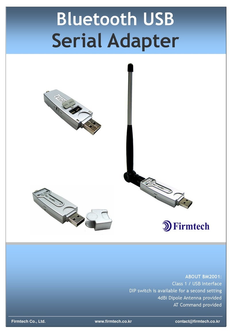
Firmtech TinyBee FZ210BS User manual

IEEE 802.15.4 Wireless
USB Serial Adapter
Model name: BM1001
User Manual ver 3.1
ABOUT FZ210BS
IEEE 802.15.4 Support
USB Interface
4dBi Dipole Antenna Provided
AT Command provided

FZ210BS Manual VERSION 0.1.0
2
(C) Copyright FIRMTECH Co., Ltd. 2005
All rights reserved
The products and operation descriptions contained herein shall be protected by copyright law.
Any part or whole of products or operation description shall not be copied, reproduced,
translated, nor transformed into readable form by electronic device or machines, without prior
consent in writing by FIRMTECH Co., Ltd.
There might be some misprinting or technical faults in the products and operation description
which are subject to change without prior notice.
FCC Information to User
This equipment has been tested and found to comply with the limits for a Class B digital device,
pursuant to Part 15 of the FCC Rules. These limits are designed to provide reasonable protection
against harmful interference in a residential installation. This equipment generates, uses and
can radiate radio frequency energy and, if not installed and used in accordance with the
instructions, may cause harmful interference to radio communications. However, there is no
guarantee that interference will not occur in a particular installation. If this equipment does
cause harmful interference to radio or television reception, which can be determined by turning
the equipment off and on, the user is encouraged to try to correct the interference by one of
the following measures:
• Reorient or relocate the receiving antenna.
• Increase the separation between the equipment and receiver.
• Connect the equipment into an outlet on a circuit different from that to which the receiver is
con-nected.
• Consult the dealer or an experienced radio/TV technician for help.
Caution
Modifications not expressly approved by the party responsible for compliance could void the
user’s authority to operate the equipment.
FCC Compliance Information : This device complies with Part 15 of the FCC Rules. Operation
is subject to the following two conditions: (1) This device may not cause harmful interference,
and (2) this device must accept any interference received, including interference that may
cause undesired operation
IMPORTANT NOTE:
FCC RF Radiation Exposure Statement:
This equipment complies with FCC RF radiation exposure limits set forth for an uncontrolled
environment. This equipment should be installed and operated with a minimum distance of 20
centimeters between the radiator and your body. This transmitter must not be co-located or
operating in conjunction with any other antenna or transmitter.

FZ210BS Manual VERSION 0.1.0
3
FIRMTECH Co., Ltd. 2005
Homepage : www.firmtech.co.kr
Tel : 82-31-719-4812
Fax : 82-31-719-4834

FZ210BS Manual VERSION 0.1.0
4
IEEE 802.15.4?
1. Features of IEEE 802.15.4
1) Wireless Personal Area Networks, WPAN : efficient management is possible by configuring home
appliances, light control, and office appliances to short range wireless network,.
2) Frequency in Use: To use ISM (Industrial, Scientific, Medical) band which does not require any
permissions to use.
- 868 ~ 870 MHz: 1 channel, 868MHz in Europe (No.0 channel)
- 902 ~ 928 MHz: 10 channels, 915MHz in the U.S.A (No.1 ~ 10 channel)
- 2.400 ~ 2.4835 GHz: 16 channels in all nations (No.11 ~26 channel)
3) Transmission Rate
- 868 ~ 870 MHz: 20Kbps
- 902 ~ 928 MHz: 40Kbps
- 2.400 ~ 2.4835 GHz: 250Kbps
4) Tx Power and working distance
- 1mW (0dBm) Inside: 30m, Outside: 100m
- Over 100m with 1mW
- Tx Power is subject to change depending on manufacturers.
5) Configuration
- Star or Peer to Peer
- 1:N or 1:1 communication
6) Reliability
- Guarantees data reliability with the cannel access using the algorithm of carrier sense multiple
access/non collision acknowledge
- Supports Network level and Device level using Authentication-Network Key and Link Key.
- Supports encrypted packet transmission using 128bit AES Encryption.
- Guarantees data reliability on the physical layer using ACK option in MAC Packet.

FZ210BS Manual VERSION 0.1.0
5
Introduction
MAC networks using IEEE 802.15.4 can be set up by using the FZ210BS, serial data communication can also
be enabled by using a USB interface.
The FZ210BS can also be used interlocking with FZ110BS/FZ760BS/FZ760BC.
< Major features of FZ210BS>
1. Based on IEEE 802.15.4
2. Supports Star, Tree, Peer to Peer Network
3. Since it is configured as a USB Interface, users can easily input or output serial data after USB Driver
install.
※Since the FZ210BS is exclusively used for serial data transmission or reception, smooth
transmission or reception of KEY/ADC/GPIO data may not be achieved, but input or output of
KEY/ADC/GPIO data can be done by using the socket inside the rubber cover at the back side of the
FZ210BS.
※Since the FZ210BS is exclusively used for serial data transmission or reception, it may not perform
smooth operation as Low Power devices, but it can be also used as an Low Power device by using the
AT Command.
To input key data as a mean of Wake Up, please use the socket inside the rubber cover on the back of
the FZ210BS.
4. Supports AT command, and control Devices by using the AT command.
5. Use 2.400 ~ 2.475 GHz(ISM Band) 15 channels (No.11 ~25 channel)
11 (0x0B): 2405MHZ, 12 (0x0C): 2410MHZ, 13 (0x0D): 2415MHZ,
14 (0x0E): 2420MHZ, 15 (0x0F): 2425MHZ, 16 (0x10): 2430MHZ,
17 (0x11): 2435MHZ, 18 (0x12): 2440MHZ, 19 (0x13): 2445MHZ,
20 (0x14): 2450MHZ, 21 (0x15): 2455MHZ, 22 (0x16): 2460MHZ,
23 (0x17): 2465MHZ, 24 (0x18): 2470MHZ, 25 (0x19): 2475MHZ,
※We request the new users of FZ210BS to read the information on this description carefully before
they start to use the products.

FZ210BS Manual VERSION 0.1.0
6
■List of contents
IMPORTANT NOTE: ......................................................................................................................................................2
FCC RF RADIATION EXPOSURE STATEMENT: ...........................................................................................................2
1. PRODUCT COMPONENTS .......................................................................................................................................7
2. PRODUCT APPEARANCE.........................................................................................................................................8
3. USB INTERFACE ......................................................................................................................................................9
4. DIP SWITCH & INTERFACE SOCKET....................................................................................................................10
5. LED INDICATION / RESET SWITCH ......................................................................................................................11
6. PRODUCT PERFORMANCE ...................................................................................................................................12
7. CURRENT CONSUMPTION ....................................................................................................................................12
8. SET VALUE OF PRODUCT.....................................................................................................................................13
9. USES GUIDE ...........................................................................................................................................................14
9-1. SERIAL DATA TRANSMISSION/RECEIPT ...................................................................................................................14
9-1-1. Serial data transmission (USB) ..............................................................................................................14
9-2. DATA RECEIPT ....................................................................................................................................................16
9-2-1. Serial data receipt(USB) ........................................................................................................................16
10. FZ210BS MANAGEMENT TIP .............................................................................................................................19
10-1. OPERATION OF SERIAL DATA TRANSMISSION/RECEIPT ...........................................................................................19

FZ210BS Manual VERSION 0.1.0
7
1. Product components
Model Name
Pictures
Q’ty
FZ210BS
1EA
FBA004DA
1EA
CD
1EA
※If you find any of above components is defective, or not included in the package, please contact the
seller you purchased.

FZ210BS Manual VERSION 0.1.0
8
2. Product Appearance
< Figure 2 Details and Dimension of FZ210BS >
SMA Connector - Connector to attach the antenna.
Power LED –shows the power status.
Status LED –shows the action status.
OK LED - shows the action status.
ERROR LED - shows the action status.
USB Input –connects the USB cable.
Reset Switch –Switch for product reset
Power ON / OFF Switch –Power Supply Switch.

FZ210BS Manual VERSION 0.1.0
9
3. USB Interface
※The FZ210BS is connected to a virtual serial port using an USB.
※As the FZ210BS uses a virtual COM Port, the virtual COM Port should be operating normally to be
used in the HOST (PC).
Signal Name
Description
STATUS (DCD)
Status Indication
TX
Transfer Data(Data Output)
RX
Received Data(Data Input)
ERROR (DTR)
Status Indication
OK (RTS)
Status Indication

FZ210BS Manual VERSION 0.1.0
10
4. Dip Switch & Interface Socket
No
Function
ON
OFF
Basic
Setting
1
Not in use
-
-
-
2
Not in use
-
-
-
3
Select firmware
download
Firmware download mode
Basic operation mode
OFF
4
Select the environment
setting mode
Environment setting mode
Basic operation mode
OFF
<Table 4-1 Features of Dip Switch >
NO.
Port
Description
1
VCC(3.3V)
3.3V Output Port
2
ADC
Analog Data Input Port
3
GPIO_0
Digital INPUT Port
4
GPIO_1
Digital INPUT Port
5
GPIO_2
Digital INPUT Port
6
GPIO_3
Digital INPUT Port
7
GPIO_4
Digital OUTPUT Port
8
GPIO_5
Digital OUTPUT Port
9
GPIO_6
Digital OUTPUT Port
10
GPIO_7
Digital OUTPUT Port
11
GND
Ground
12
KEY
Digital Data Input Port
< Table 4-2 Features of Interface Socket >

FZ210BS Manual VERSION 0.1.0
11
5. LED Indication / Reset Switch
LED Type
State
Description
Power LED
Power input
Red Power LED is turned on.
STATUS LED
Status LED
Confirming of the
device’s operation
status
When the device is operating for
general functions, the Status LED blinks
at the interval of one second.
When the device is operated for a
bridging function, the Status LED is
turned on.
confirming of operation
mode
The status LED is turned off in case of
the AT Command mode
OK LED
Confirming of data
transmission
The OK LED blinks once when the data
transmission is completed.
Confirming of the
operation mode
The OK LED is on in case of the AT
Command mode.
ERROR LED
Confirming of data
transmission
The ERROR LED blinks once when the
data transmission is not completed.
Confirming of the
Operation mode
The ERROR LED is on in case of the AT
Command mode

FZ210BS Manual VERSION 0.1.0
12
6. Product Performance
List
Specification
Wireless Spec.
IEEE 802.15.4 Support
Communication Distance
120 M
Frequency Range
2.4 GHz ISM Band
Sensitivity
-98 dBm
Transmit Power
6 dBm
Size
23.00 mm X 56.00 mm X 10.50 mm
Input Power
5V
Current Consumption
60 mA (Max)
Operating Temperature
-20 ℃- +50 ℃
Max Operating Temperature
-30 ℃- +80 ℃
Communication Speed
9,600 bps ~ 230,400 bps
Antenna
Dipole Antenna (4 dBi)
Interface
USB
7. Current consumption
Device type
Current consumption
Low power
consumption
mode
Data transmission/receipt
Wake-up mode
-
50mA
Low power consumption mode 1(optional)
12mA
-
Low power consumption mode 2(optional)
12mA
-
Low power consumption mode 3(optional)
12mA
-
Testing Environment: 38400bps

FZ210BS Manual VERSION 0.1.0
13
8. Set value of Product
List
Initial set value
Device Version
FZx10 Vx.x.x
Device Ext Address
001551xxxxxxxxxx
Device Pan ID
1234
Device Channel
14
Device Transmit Power
00
UART (baud rate, data bit, parity bit, stop bit)
38400 (8, N, 1 fixed)
KEY Option
1(Enable)
ADC Option
0(Disable)
Count Option
0(Disable)
GPIO Option
0
GPIO Clear Option
1(Enable)
Internal Time
10
Power Mode
0
Local Device Address
0000
Target Device Address
FFFF
Link Quality Option
0(Disable)
End of Length
0
Bridge Option
0(Disable)
Bridge 1 Address
FFFF
Bridge 2 Address
FFFF
Bridge 3 Address
FFFF
Bridge 4 Address
FFFF
Start Message Option
1(Enable)
ID Option
0(Disable)
Device Name
FZx10XX
To change the set values of FZ210BS, use PC Software (Window HyperTerminal) after connecting FZ210BS
to PC with AT Command.
Please, refer to the “Appendix_3_details of setting configuration”.

FZ210BS Manual VERSION 0.1.0
14
9. Uses Guide
Basic data sent by using the FZ210BS is serial (USB) data.
Since the FZ210BS is exclusively used for serial data transmission or reception, smooth transmission
or reception of KEY/ADC/GPIO data may not be achieved, but input or output of KEY/ADC/GPIO data
can be done by using the socket inside the rubber cover at the back side of the FZ210BS.
Since the FZ210BS is exclusively used for serial data transmission or reception, it may not perform
smooth operation as Low Power devices, but it can be also used as an Low Power device by using the
AT Command.
To input key data as a mean of Wake Up, please use the socket inside the rubber cover on the back of
the FZ210BS.
9-1. Serial Data Transmission/receipt
Note : As the FZ210BS uses a virtual COM Port, the virtual COM Port should be operating normally to
be used in the HOST (PC).
The following is a procedure for FZ210BS Set-up using Serial communication (HyperTerminal) Program.
The signal speed of FZ210BS is basically 38400bps.
9-1-1. Serial data transmission (USB)
(1) Connect FZ210BS (Device 1) to PC, and turn the power of FZ210BS ON.
As the FZ210BS uses a virtual COM Port using an USB, the hyper terminal cannot be run when the
device is powered on in advance.
(2) Execute Hyper Terminal.
Select [Start][All Programs][Accessories][Communication][Hyper Terminal] in order, and then a
window for Connection Set-up comes up. Put a name in the name blank, and click the OK button.

FZ210BS Manual VERSION 0.1.0
15
When a window for Connection target comes up, select COM ports connected to FZ210BS, and click the OK
button.
Select each blank as below “Bit/sec: 38400, data Bit: 8, Parity: None, Stop Bit: 1, Flow Control: None”,
and click the OK button. Hyper Terminal is executed.

FZ210BS Manual VERSION 0.1.0
16
(3) Reset the FZ210BS.
When the FZ210BS operates normally, it outputs “FZx10 START
OK” message.
(4) Input “1234567890” into Hyper Terminal.
The “1234567890” entered by users is not seen on the hyper
terminal.
(5) FZ210BS transmits the serial data to its target device.
※Whenever serial data is entered, the FZ210BS sends out wireless data (after certain internal time
delay) and OK or ERROR LED shows its status.
9-2. Data receipt
9-2-1. Serial data receipt(USB)
Serial (USB) data received wirelessly is output to the USB port of the FZ210BS.
Serial (USB) data is output in the same data format as it was sent from the sending device.

FZ210BS Manual VERSION 0.1.0
17
(1) Connect FZ210BS(Device 2) to PC, and turn the power of FZ210BS ON.
(2) Execute Hyper Terminal.
Select [Start][All Programs][Accessories][Communication][Hyper Terminal] in order, and then a
window for Connection Set-up comes up. Put a name in the name blank, and click the OK button.
When a window for Connection target comes up, select COM ports connected to FZ210BS, and click the OK
button.

FZ210BS Manual VERSION 0.1.0
18
Select each blank as below “Bit/sec: 38400, data Bit: 8, Parity: None, Stop Bit: 1, Flow Control: None”,
and click the OK button. Hyper Terminal is executed.
(3) Reset the FZ210BS.
When the FZ210BS operates normally, it outputs “FZx10 START
OK” message.
(4) Received serial data by wireless is outputted via HyperTerminal.

FZ210BS Manual VERSION 0.1.0
19
10. FZ210BS Management TIP
Without additional setting, all FZ210BS around receives data if data is inputted after the power of
device is approved.
A lot of traffic in network can cause trouble with data transmission/receipt.
If big size of data is transmitted successively or in short time, traffic increase.
Extensive care is required of the size of data and time space for transmission.
10-1. Operation of serial data transmission/receipt
< Figure 10-1 serial data transmission/receipt >
(1) Turn the power of FZ210BS on.
(2) Input serial data into FZ210BS.
(3) All FZ210BS around output received serial data by wireless.

FZ210BS Manual VERSION 0.1.0
20
※References
Appendix_0: details of FZxx0_USB Driver
Appendix_1: details of FZx10_low power_ADC_KEY_GPIO
Appendix_2: details of FZx10_AT Command
Appendix_3: details of FZx10_Environment Setup
Appendix_4: details of FZx10_Bridge Mode
Appendix_5: details of FZx10_Location mode
Appendix_6: details of FZx10_Device name Transmission
Appendix_7: details of FZx10_Local Address & Target Address
Table of contents
Other Firmtech Adapter manuals

Firmtech
Firmtech FBS100BC-SPP User manual
Firmtech
Firmtech FB100AS-F User manual
Firmtech
Firmtech TinyBee FZ100BS User manual

Firmtech
Firmtech FB100AS User manual
Firmtech
Firmtech FZ200BS User manual
Firmtech
Firmtech FB100AS User manual
Firmtech
Firmtech FB200AS User manual

Firmtech
Firmtech FB100AS User manual

Firmtech
Firmtech FB200AS-F User manual

Firmtech
Firmtech FB200AS User manual
Popular Adapter manuals by other brands
D-Link
D-Link DSM-260 Quick installation guide
SMC Networks
SMC Networks ETHEREZ 8416 manual
SMC Networks
SMC Networks SMCWAA-B Quick installation guide
Shadin Avionics
Shadin Avionics AIS-380 installation manual
Panasonic
Panasonic AJ-B95 operating instructions
Tektronix
Tektronix TEK-USB-488 Specification sheet
