Fisher 3582 User manual

D200138X012
3582 Series Valve Positioners, Type 3582i Valve
Positioner, and 3583 Series Valve Stem Position
Transmitters
Contents
Introduction
2. . . . . . . . . . . . . . . . . . . . . . . . . . . . . .
Scope of Manual 2. . . . . . . . . . . . . . . . . . . . . . . . . . . . .
Description 2. . . . . . . . . . . . . . . . . . . . . . . . . . . . . . . . . .
Type Number Descriptions 2. . . . . . . . . . . . . . . . . . .
Specifications 4. . . . . . . . . . . . . . . . . . . . . . . . . . . . . . .
Installation
5. . . . . . . . . . . . . . . . . . . . . . . . . . . . . . . .
Mounting 6. . . . . . . . . . . . . . . . . . . . . . . . . . . . . . . . . . . .
Changing Cam Position 9. . . . . . . . . . . . . . . . . . . . . . .
Pressure Connections 9. . . . . . . . . . . . . . . . . . . . . . . .
Supply Connection 10. . . . . . . . . . . . . . . . . . . . . . . .
Output Connection 11. . . . . . . . . . . . . . . . . . . . . . . .
Instrument Connection 11. . . . . . . . . . . . . . . . . . . . .
Diagnostic Connections 11. . . . . . . . . . . . . . . . . . . .
Vent 12. . . . . . . . . . . . . . . . . . . . . . . . . . . . . . . . . . . . . .
Electrical Connections for Type 3582i
Valve Positioner 12. . . . . . . . . . . . . . . . . . . . . . . . .
Installation Of Type 582i Converter 13. . . . . . . . . . .
Operating Information
14. . . . . . . . . . . . . . . . . .
Valve Positioner Cam Information 14. . . . . . . . . . . .
Valve Stem Position Transmitter Cam
Information 15. . . . . . . . . . . . . . . . . . . . . . . . . . . . .
Valve Positioner Bypass Operation 15. . . . . . . . . . .
Input Signal Ranges 16. . . . . . . . . . . . . . . . . . . . . . . .
Valve Positioner Split-Range Operation 16. . . . . . .
Changing Valve Positioner Action 17. . . . . . . . . . . .
Changing Valve Stem Position Transmitter
Action 17. . . . . . . . . . . . . . . . . . . . . . . . . . . . . . . . . .
Figure 1. Typical Mounting for the 3582 Series, Type 3582i, and 3583 Series Positioners and Transmitters
W5498/IL W5500/IL W5499/IL
Instruction Manual
Form 5054
June 1998 3582 and 3583 Series

3582 and 3583 Series
2
Contents (cont’d)
Calibration Of Valve Positioner Or Valve
Stem Position Transmitter
17. . . . . . . . . . . . .
Beam Alignment 17. . . . . . . . . . . . . . . . . . . . . . . . . . .
Calibration 19. . . . . . . . . . . . . . . . . . . . . . . . . . . . . . . .
Principle of Operation
19. . . . . . . . . . . . . . . . . .
3582 Series Valve Positioners 19. . . . . . . . . . . . . . .
Type 3582i Valve Positioner 20. . . . . . . . . . . . . . . . .
3583 Series Valve Stem Position Transmitters 20.
Maintenance
21. . . . . . . . . . . . . . . . . . . . . . . . . . . . .
Changing the Range Spring 22. . . . . . . . . . . . . . . . .
Replacing Gaskets 22. . . . . . . . . . . . . . . . . . . . . . . . .
Replacing the Nozzle O-Ring 22. . . . . . . . . . . . . . . .
Removing and Replacing the Relay 23. . . . . . . . . . .
Relay Maintenance 23. . . . . . . . . . . . . . . . . . . . . . . . .
Adjusting the Flapper Pivot 24. . . . . . . . . . . . . . . . . .
Replacing the Type 582i Converter
Primary O-Ring and Filter 24. . . . . . . . . . . . . . . . .
Replacing the Type 582i Converter Housing
Cap O-Ring 24. . . . . . . . . . . . . . . . . . . . . . . . . . . . .
Removing the Type 582i Converter 24. . . . . . . . . . .
Reassembling the Type 582i Converter 25. . . . . . .
Parts Ordering
25. . . . . . . . . . . . . . . . . . . . . . . . . . .
Parts Kits
25. . . . . . . . . . . . . . . . . . . . . . . . . . . . . . . .
Parts List
25. . . . . . . . . . . . . . . . . . . . . . . . . . . . . . . . .
Introduction
Scope of Manual
This instruction manual includes installation, operation,
calibration, maintenance, and parts ordering informa-
tion for the 3582 Series pneumatic valve positioners,
the Type 3582i electro-pneumatic valve positioner,
and the 3583 Series pneumatic valve stem position
transmitters. Refer to separate instruction manuals for
information on the control valve, actuator, and acces-
sories.
Only personnel qualified through training or experience
should install, operate, or maintain the valve positioner
or valve stem position transmitter. If there are any
questions concerning the instructions in this manual,
contact your Fisher sales office or representative be-
fore proceeding.
Description
The 3582 Series pneumatic valve positioners and the
Type 3582i electro-pneumatic valve positioner shown
in figure 1 are used with diaphragm-actuated, sliding-
stem control valve assemblies. The pneumatic valve
positioners receive a pneumatic input signal from a
control device and modulate the supply pressure to
the control valve actuator. The positioner adjusts the
actuator supply pressure to maintain a valve stem
position proportional to the pneumatic input signal.
Type 3582NS positioners meet typical requirements of
the nuclear power industry. The Type 3582NS
construction includes materials that provide superior
performance at elevated temperature and radiation
levels. The O-rings are EPDM (ethylene propylene)
and the diaphragms are EPDM/Nomex. EPDM(1) dem-
onstrates superior temperature capability and shelf life
over nitrile. The Nomex diaphragm fabric demon-
strates improved strength retention at elevated tem-
perature and radiation conditions.
In addition, the Type 3582NS positioner is qualified
“commercial grade dedicated” under Fisher’s
10CFR50, Appendix B, quality assurance program.
These can be supplied as 10CFR21 items.
The Type 3582i is an electro-pneumatic valve position-
er, consisting of a Type 582i electro-pneumatic con-
verter installed on a Type 3582 pneumatic valve posi-
tioner. The Type 3582i valve positioner provides an
accurate valve stem position that is proportional to a
dc current input signal.
The Type 582i electro-pneumatic converter is a modu-
lar unit that can be installed at the factory or in the
field. However, do not plan to install a Type 582i con-
verter on an existing positioner until you contact your
Fisher sales office or representative for application
assistance.
The Type 582i converter receives the dc current input
signal and, through a nozzle/flapper arrangement, pro-
vides a proportional pneumatic output signal. This
pneumatic output signal provides the input signal to
the pneumatic valve positioner, eliminating the need
for a remote-mounted transducer.
The 3583 Series pneumatic valve stem position trans-
mitters are for use with sliding-stem diaphragm actua-
tors. These units provide an output signal that is di-
rectly proportional to the valve stem position.
Refer to the type number description for a detailed
explanation of type numbers.
Type Number Descriptions
The following descriptions provide specific information
on the different valve positioner or valve stem position
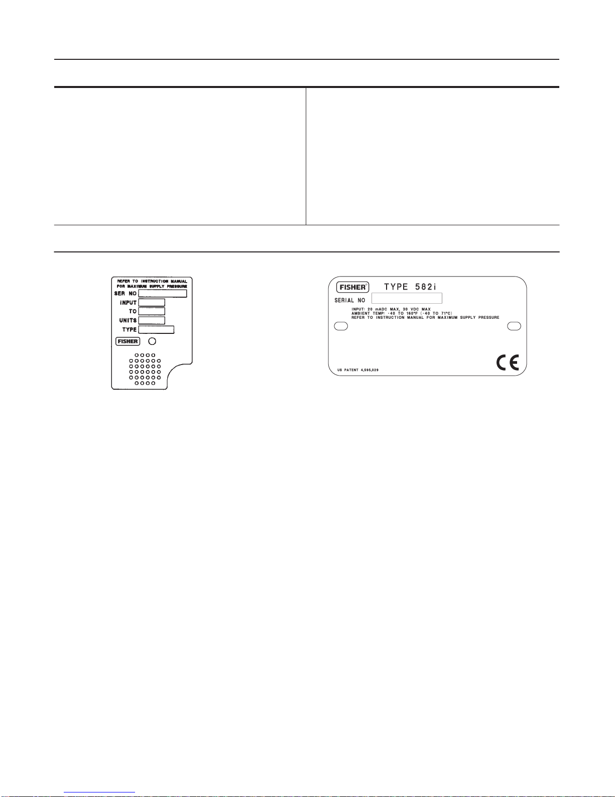
transmitter constructions. If the type number is not
known, refer to the nameplate on the positioner. For
the location of the nameplate, refer to key 25 in figure
21.
1. Use a clean, dry, oil-free air supply with instruments containing EPDM components.
EPDM is subject to degradation when exposed to petroleum-based lubricants.

3582 and 3583 Series
3
Table 1. Specifications for 3582 Series and Type 3582i Valve Positioners
Input Signal(1),
3582 Series:
J3 to 15 psig (0.2 to 1.0 bar), J6 to 30 psig (0.4
to 2.0 bar), or Jsplit range, see table 5
Type 3582i:
4 to 20 mA dc constant current with 30 V dc maxi-
mum compliance voltage, can be split range, see
table 5
Equivalent Circuit for Type 3582i
The Type 582i converter equivalent circuit is 120
ohms, shunted by three 5.6-volt zener diodes (see
figure 11)
Output Signal(1)
Type: Pneumatic pressure as required by actuator
up to 95 percent of maximum supply
Action(1):Field-reversible between Jdirect and
Jreverse within the pneumatic valve positioner
Supply Pressure(1)
Recommended: 5 psi (0.3 bar) above actuator re-
quirement
Maximum: 50 psig (3.4 bar) or pressure rating of
actuator, whichever is lower
Input Bellows Pressure Rating(2)
See table 4 for minimum and maximum pressure
ratings (allowable input signal) for each available
range spring
Maximum Steady-State Air Consumption(1)(3)
For 3582 Series
20 Psig (1.4 bar) Supply:
14.0 scfh (0.38 normal
m3/hr)
30 Psig (2.0 bar) Supply:
18.0 scfh (0.48 normal
m3/hr)
35 Psig (2.4 bar) Supply:
20.0 scfh (0.54 normal
m3/hr)
For Type 3582i Only
20 Psig (1.4 bar) Supply:
17.2 scfh (0.46 normal
m3/hr)
30 Psig (2.0 bar) Supply:
21.4 scfh (0.58 normal
m3/hr)
35 Psig (2.4 bar) Supply:
23.8 scfh (0.64 normal
m3/hr)
Maximum Supply Air Demand(1)
For 3582 Series and Type 3582i
20 Psig (1.4 bar) Supply:
164.5 scfh (4.7 normal
m3/hr)
30 Psig (2.0 bar) Supply:
248.5 scfh (7.0 normal
m3/hr)
35 Psig (2.4 bar) Supply:
285.5 scfh (8.1 normal
m3/hr)
Performance
For 3582 Series
Independent Linearity
(1)
:
±1 percent of output signal
span
Hysteresis
(1)
:
0.5 percent of span
For Type 3582i Only
Independent Linearity
(1)
:
±2 percent of output signal
span
Hysteresis
(1)
:
0.6 percent of span
Electromagnetic Interference (EMI)
(1)
:
When tested
per SAMA Standard PMC 33.1-1978, change in
steady-state deviation is less than ±1% in an elec-
tromagnetic field classified as 3-abc with a field
strength of 30 V/m. Positioner is tested with hous-
ing cap on and with external field wiring in rigid met-
al conduit.
For 3582 Series and Type 3582i
Open Loop Gain (Output Signal)
(1)
:
J100 in the range of 3 to 15 psig (0.2 to 1.0 bar)
J55 in the range of 6 to 30 psig (0.4 to 2.0 bar)
Operating Influences(1)
Supply Pressure, For 3582 Series Units: Valve
travel changes less than 0.25 percent per 2 psi
(1.67 percent per bar) change in supply pressure
Supply Pressure, For Type 3582i Units: Valve
travel changes less than 1.5 percent per 2 psi (3.62
percent per bar) change in supply pressure
Operative Temperature Limits(1)(2)
Standard Construction, For 3582 Series and
Type 3582i Units: –40 to +160_F (–40 to +71_C)
Type 3582NS Units: –40 to +180_F (–40 to
+82_C) with EPDM elastomers
High-Temperature Construction, For Types
3582A and C only: 0 to +220_F (–18 to +104_C)
without gauges
Electrical Classification for Type 3582i
Please refer to the Hazardous Area Classifications
Bulletins for specific approvals. Also, refer to the
nameplates shown in figure 2 for the location of po-
sitioner or transmitter classification information and
approval descriptions.
Housing Classification for Type 3582i
NEMA 3, IEC 529 IP54: Mount instrument with vent
on the side or bottom if weatherproofing is a con-
cern.
- Continued -

3582 and 3583 Series
4
Table 1. Specifications for 3582 Series and Type 3582i Valve Positioners (Continued)
Pressure Gauges
1-1/2 inch (40 mm) diameter with plastic case and
brass connection Jtriple scale (PSI, MPa, and bar)
or Jdual scale (PSI and kg/cm2)
Pressure Connections
1/4-inch NPT female
Electrical Connection for Type 3582i
1/2-14 NPT conduit connection
Maximum Valve Stem Travel
4-1/8 inches (105 mm); adjustable to obtain lesser
travels with standard input signals
Characterized Cams
See characterized cams section
Approximate Weight
3582 Series Units: 5-1/2 pounds (2.5 kg)
Type 3582i: 8 pounds (3.6 kg)
1. This term is defined in ISA Standard S51.1-1979.
2. Do not exceed any of the pressure or temperature limits in this instruction manual. Also, any applicable standard or code should not be exceeded.
3. Scfh—Standard cubic feet per hour (60_F and 14.7 psia); normal m3/hr—normal cubic meters per hour (0_C and 1.01325 bar, absolute).
11B5625-ESHT B / DOC
13B8758-C SHT 1 / DOC
Figure 2. Typical Nameplates
Type 3582—Pneumatic valve positioner with bypass
and instrument, supply, and output pressure gauges.
Type 3582A—Pneumatic valve positioner without by-
pass and without pressure gauges.
Type 3582C—Pneumatic valve positioner without by-
pass and with automotive tire valves instead of pres-
sure gauges.
Type 3582D—Pneumatic valve positioner with bypass
and with automotive tire valves instead of pressure
gauges.
Type 3582G—Pneumatic valve positioner without by-
pass and with instrument, supply, and output pressure
gauges.
Type 3582NS—Pneumatic valve positioner for nuclear
service applications with or without bypass and with
automotive tire valves instead of pressure gauges.
Type 3582i—Electro-pneumatic valve positioner with-
out bypass; with Type 582i converter; and with: supply
and output pressure gauges, automotive tire valves, or
pipe plugs.
Type 582i—Electro-pneumatic converter with: supply
and output pressure gauges, automotive tire valves, or
pipe plugs. Used for conversion of a 4 to 20 milliam-
pere input signal to a 3 to 15 psig (0.2 to 1.0 bar) input
signal for the pneumatic valve positioner.
Type 3583—Pneumatic valve stem position transmit-
ter with supply and output pressure gauges.
Type 3583C—Similar to the Type 3583 valve stem
position transmitter except with automotive tire valves
in place of pressure gauges.
Specifications
Specifications for the valve positioners are shown in
table 1. Specifications for the valve stem position
transmitters are shown in table 2.
Refer to the unit nameplate to determine the type of
positioner or transmitter, supply pressure, etc. A typi-
cal nameplate is shown in figure 2.

3582 and 3583 Series
5
Table 2. Specifications for 3583 Series Valve Stem Position Transmitters
Input Signal(1)
4-1/8 inches (105 mm) of valve stem travel; adjust-
able to obtain full output signal with lesser stem
travels
Output Signal(1)
Type: J3 to 15 psig (0.2 to 1.0 bar) or J6 to 30
psig (0.4 to 2.0 bar) pneumatic pressure
Action: Field-reversible between direct and reverse
Output Bellows Pressure Rating(2)
See table 4 for minimum and maximum pressure
ratings (allowable input signal) for each available
range spring
Supply Pressure(1)
Recommended: 5 psi (0.3 bar) above upper limit of
output signal range
Maximum: 35 psig (2.4 bar) or pressure rating of
connected equipment, whichever is lower
Maximum Steady-State Air Consumption(1)(3)
20 Psig (1.4 bar) Supply:
14.0 scfh (0.38 normal
m3/hr)
30 Psig (2.0 bar) Supply:
18.0 scfh (0.48 normal
m3/hr)
35 Psig (2.4 bar) Supply:
20.0 scfh (0.54 normal
m3/hr)
Reference Accuracy(1)
±1 percent of output signal span
Operating Influence(1)
Output signal changes 0.23 percent per 2 psig (1.67
percent per bar) change in supply pressure
Operative Ambient Temperature Limits(1)(2)
Standard Construction, 3583 Series: –40 to
+160 _F (–40 to +71_C)
High-Temperature Construction, Type 3583C
only: 0 to +220 _F (–18 to +104_C)
Pressure Connections
Supply and output pressure connections are
1/4-inch NPT female
Maximum Valve Stem Travel
4-1/8 inches (105 mm); adjustable to obtain full out-
put signal with lesser stem travels
Cam
Linear
Approximate Weight
5-1/2 pounds (2.5 kg)
1. This term is defined in ISA Standard S51.1-1979.
2. Do not exceed any of the pressure or temperature limits in this instruction manual. Also, any applicable standard or code should not be exceeded.
3. Scfh—Standard cubic feet per hour (60_F and 14.7 psia); normal m3/hr—normal cubic meters per hour (0_C and 1.01325 bar, absolute).
Installation
Note
All valve positioners and valve stem
position transmitters are shipped with
foam rubber packing material inside the
case. Remove the cover (key 33, figure
21) and the packing material before at-
tempting to operate the unit. Make sure
all vent openings are clear before instal-
lation of the unit and that they remain
clear during use.
Typically, the positioner or transmitter is ordered with
the actuator. If so, the factory mounts the valve posi-
tioner or valve stem position transmitter and connects
the valve positioner output to the actuator. If a Type
67AFR filter-regulator is specified, it may be integrally
mounted to the valve positioner or valve stem position
transmitter, except for the Type 3582NS positioner.
For the Type 3582NS, the Type 67AFR is separately
mounted, not integrally mounted to the positioner.
Note
In some cases, alignment and calibra-
tion of the valve positioner or valve
stem position transmitter at the factory
may not be possible, and field align-
ment and calibration is required. Before
putting the valve positioner or valve
stem position transmitter into service,
check the operation of the unit to be
sure it is calibrated. If the valve posi-
tioner or valve stem position transmitter
requires alignment or calibration, refer
to the appropriate calibration instruc-
tions in this manual.
If the valve positioner or valve stem position transmit-
ter is ordered separately, disconnected, or removed
from the actuator, refer to the appropriate sections of
this manual for installation information.

3582 and 3583 Series
6
Figure 3. Mounting Assembly
41B8569-CSHT 1 AND 2 / DOC
Mounting
Key numbers used in this procedure are shown in fig-
ure 3 except where indicated.
1. Figure 3 shows the various mounting parts required
for mounting on Fisher actuators. Mounting parts for
Fisher actuators that require spacers have the spacers
(key 50) included. Type 657 and 667 actuators, sizes
70 through 100, with or without a side-mounted hand-
wheel, use spacers (keys 97 and 102) between the
stem connector and the connector arm (key 48). On all
other actuators that use spacers, place the spacers
(key 50) between the mounting plate (key 63) and the
actuator mounting boss.
When mounting the valve positioner or valve stem
position transmitter on an actuator by another
manufacturer, provide spacers, if necessary, by cut-
ting sections from 1/2- or 3/8-inch pipe so that the ‘‘X’’
dimension matches the value given in figure 6.
2. As shown in figures 3 and 4, attach the connector
arm (key 48) to the stem connector so that the con-
nector arm extends through the yoke legs on the side
of the lower mounting boss.
3. Attach the valve positioner or valve stem position
transmitter to the mounting plate (key 63) using the
holes shown in figure 5.
4. Mount the Type 67AFR regulator:

3582 and 3583 Series
7
Table 3. 3582 and 3583 Series Mounting Information
ACTUATOR
TYPE ACTUATOR
SIZE
MAXIMUM
TRAVEL MOUNTING
HOLES
SET NO (1)
TRAVEL PIN
POSITION(2) ACTUATOR
TYPE ACTUATOR
SIZE
MAXIMUM
TRAVEL
MOUNTING
HOLES
SET NO.(1) TRAVEL PIN
POSITION(2)
TYPE
SIZE
Inch mm SET NO.(1)
POSITION()
TYPE
SIZE
Inch mm 657 667
POSITION()
513 & 513R 20
32 3/4
3/4 19
19 2
2Normal
Normal 657 & 667
Without
Side-Mounted
30
34
40
3/4
1-1/8
1-1/2
19
19
38
3
3
2
4
2
3
Normal
Normal
Normal
656 30
40
60
2
3-1/2
4
51
89
102
4
4
4
Inverted
Inverted
Inverted
Side Mounted
Handwheel 45
45
50
60
3/4
2
2
2
19
51
51
51
1
1
1
1
4
1
2
2
Inverted(3)
Normal
Normal
Normal
657-4 Without
Side-Mounted
Handwheel
70 4 102 3 Inverted 70 2
2-1/16–3
3-1/16–4
51
52–76
78–102
2
3
3
1
2
1
Normal
Normal
Inverted(4)
657-4 With
Side-Mounted
Handwheel
70
87 4
4102
102 2
1Inverted
Inverted 80 3 76 2 2 Normal
657-8 30
34
40
40
2-1/8
2-1/8
3-1/8
3-1/2
54
54
79
89
3
3
3
3
Normal
Normal
Normal
Normal
87 2
2-1/16–3
3-1/16–4
51
52–76
78–102
2
2
3
2
2
1
Normal
Normal
Inverted(4)
46
46
47
3-1/8
4-1/8
3-1/8
79
105
79
2
2
2
Normal
Normal
Inverted
100 4 102 4 4 Inverted
47
60
70
4-1/8
4-1/8
4-1/8
105
105
105
1
4
2
Inverted
Inverted
Inverted
657 & 667
With
Side-Mounted
34
40
45
3/4
1-1/2
2
19
38
51
2
1
1
2
2
4
Normal
Normal
Normal
667-4 Without
Side-Mounted
Handwheel
70
87 4
4102
102 1
1Normal
Normal
Side Mounted
Handwheel 50
60
70
80
2
2
4
3
51
51
102
76
4
3
2
2
1
1
2
2
Inverted(4)
Inverted(4)
Inverted
Normal
87 3
3-1/16–4 76
78–102 2
22
1Normal
Inverted
1. The indicated set number should be considered a reference point only, due to the variables related to making up the stem connection.
2. Normal position is shown in figure 4.
3. Travel pin position for Type 657 is normal.
4. Travel pin position for Type 667 is normal.
Figure 4. Isometric View Showing Motion Feedback
Arrangement and Typical Stem Connection
CV1768-C
A1397–2/IL
3582 Series valve positioners (except Type
3582NS) and 3583 Series valve stem position
transmitters, mount the regulator on the integral boss
on the bypass block.
Type 3582NS valve positioners, use the
mounting plate with provision for separately mounting
the Type 67AFR regulator. Separately mount the posi-
tioner and the regulator on the mounting plate.
Type 3582i valve positioners, mount the regu-
lator on the integral boss that is part of the Type 582i
converter housing.
5. As shown in figure 5, the mounting bracket has four
sets of holes for mounting the assembly to the actua-
tor. Refer to table 3 to determine which set of mount-
ing holes to use, then attach the assembly to the lower
mounting pad on the actuator.
CAUTION
To avoid equipment damage, be certain
the connector arm clears the valve posi-
tioner or valve stem position transmitter
case as the actuator moves through its
complete stroke.

3582 and 3583 Series
8
Figure 5. Mounting Plates Used with 3582 Series Valve Positioners and 3583 Series Valve Stem Position Transmitters
BF2635-B/DOC
HOLES FOR MOUNTING
PLATE TO ACTUATOR
HOLES FOR MOUNTING
POSITIONER TO PLATE
SET NO. 1
SET NO. 2
SET NO. 3
SET NO. 4
HOLES FOR
MOUNTING REGULATOR
HOLES FOR MOUNTING
PLATE TO ACTUATOR
HOLES FOR MOUNTING
POSITIONER TO PLATE
6. Position the actuator to its mid-travel position using
a handwheel or manual loading regulator.
7. Slip the round end of the travel pin (key 60) into the
rotary shaft arm (key 2) slot as shown in figure 4.
8. Slide the square end of the travel pin into the pin
holder and pin lock (keys 61 and 59). Place the pin
lock and holder into the slot in the connector arm (key
48). Screw the cap nut (key 62) onto the pin lock (key
59), but do not tighten.
9. With the actuator at its mid-travel position, lift the
rotary shaft arm so that the 0-degree index marks on
the rotary shaft arm are aligned with the case index
marks as shown in figure 7.
CAUTION
Never set the travel pin at a setting that
is less than the actual actuator stroke.
Setting the travel pin at a setting that is
less than the actual actuator stroke will
cause the cam to rotate more than 60
degrees, causing damage to the cam or
other parts.
10. Position the travel pin so that it is perpendicular to
the connector arm and aligns with the correct actuator
stem travel index on the rotary shaft arm. Tighten the
cap nut (key 62 in figure 4).
11. Check the travel pin setting using the following
procedures:
For standard travel pin setting (that is, with the
travel pin setting equal to total actuator travel). Stroke
the actuator to each end of its travel. At each end of
travel, the 30-degree index marks on the rotary shaft
arm should align with the case index marks. If the in-
dex marks are not in line, loosen the cap nut (key 62)
and slide the travel pin (key 60) in the rotary shaft arm
slot until the 30-degree index marks align with the
case index marks. Be sure the travel pin remains per-
pendicular to the connector arm. After making this ad-
justment, tighten the cap nut and re-check the arm at
the mid-travel position. If the 0-degree index marks do
not align, repeat this procedure.
For special travel pin setting (that is, with the
travel pin setting greater than total actuator travel).
Check the index marks using a procedure similar to
the standard settings procedure. The arm will not ro-
tate a full 60 degrees as the actuator is stroked, and
the 30-degree index marks on the cam will be short of
aligning with the case index marks. If necessary, ad-
just the travel pin position so that the 30-degree marks
are the same distance from the respective case index
mark at each end of actuator travel.

3582 and 3583 Series
9
11B6520-C/DOC
30_MAX.
30_MAX.
X
STEM
X
STEM
TRAVEL 3/8-Inch
(9.5 mm) Stem 1/2-Inch
(12.7 mm) Stem 3/4-Inch
(19.1 mm) Stem
Inches
1-1/8 or less
1-1/2
2
2-1/2
3
3.19
3.56
4.00
4.44
4.88
3.44
3.81
4.25
4.69
5.12
3.94
4.31
4.75
5.19
5.62
3-1/2
45.31
5.75 5.56
6.00 6.06
6.50
Millimeters
29 or less
38
51
64
76
81
90
102
113
124
87
97
108
119
130
100
109
121
132
143
89
102 135
146 141
152 154
165
Figure 6. Spacing for Mounting on Other Than Fisher Actuators
Changing Cam Position
Refer to figure 21 for a typical cam illustration and key
number locations.
Note
DFor Valve Positioners: The small
arrow on the cam must point in the di-
rection of stem movement with increas-
ing actuator diaphragm pressure.
DFor Valve Stem Position Transmit-
ters: If the arrow on the cam points up
toward the nozzle, output pressure in-
creases with downward stem move-
ment. If the arrow points down, output
pressure decreases with downward
stem movement.
If the arrow is pointing in the wrong di-
rection, use the following procedure to
remove, reverse, and re-install the cam.
When mounting a valve positioner or valve stem posi-
tion transmitter, check to see if the correct cam (key 4)
and cam position has been selected. To change the
cam or cam position, unhook the extension spring (key
38), and remove the cam bolt and locking nut (keys 6
and 45). Remove the cam and spring retainer bracket
(key 43).
To install the cam, screw the locking nut all the way
onto the cam bolt. Attach the cam and spring retainer
bracket to the shaft assembly with the cam bolt. Tight-
en the bolt to secure the cam. Then, tighten the lock-
ing nut against the spring retainer bracket. Hook the
spring into the spring retainer bracket.
Figure 7. Rotary Shaft Arm and Case Index Marks
70CA0750-C
A2452-2/IL
Details on cam characteristics can be found in the
cam information portion of the operating information
section.
Pressure Connections
WARNING
Valve positioners and valve stem posi-
tion transmitters are capable of provid-
ing full supply pressure to connected
equipment. To avoid personal injury and
equipment damage, make sure the sup-
ply pressure never exceeds the maxi-
mum safe working pressure of any con-
nected equipment.

3582 and 3583 Series
10
11B6519-F
11B6520-E
C0775/IL
Figure 8. Typical Dimensions and Connections
9.88
(251.0)
7.19
(182.6)
5.56
(141.2)
4.69
(119.1)
.31
(7.9)
11.44
(290.6)
.34 (8.6) ∅HOLES
SPACED .69 (17.5) APART
5.50
(139.7)
2.25
(51.1)
.50
(12.7)
10.50
(266.7)
5.56
(141.2)
5.00
(127.0)
.31
(7.9)
9.94
(252.5)
5.50
(139.7)
2.25
(57.1)
.50
(12.7)
INCH
(mm)
.34 (8.6) ∅HOLES
SPACED .69 (17.5) APART
TYPE 3582
(DIMENSIONS FOR TYPES 3582A, C, D, G, AND NS ARE THE SAME)
Pressure connections are shown in figure 8. All pres-
sure connections are 1/4-inch NPT female. Use
3/8-inch tubing for all pressure connections. After
making pressure connections, turn on the supply pres-
sure and check all connections for leaks.
Supply Connection
WARNING
Personal injury or property damage may
occur from an uncontrolled process if
the supply medium is not clean, dry, oil-
free air, or non-corrosive gas. Industry
instrument air quality standards de-
scribe acceptable dirt, oil, and moisture
content. Due to the variability in nature
of the problems these influences can
have on pneumatic equipment, Fisher
Controls has no technical basis to rec-
ommend the level of filtration equipment
required to prevent performance degra-
dation of pneumatic equipment. A filter
or filter regulator capable of removing
particles 40 microns in diameter should
suffice for most applications. Use of
suitable filtration equipment and the es-
tablishment of a maintenance cycle to
monitor its operation is recommended.

3582 and 3583 Series
11
12B8045-A
A6077–1/IL
12B8046-A
A6078–1/IL
Figure 9. Diagnostic Connections
STEM PROVIDED
WHEN GAUGE IS
SPECIFIED
Supply pressure must be clean, dry, oil-free(2) air or
noncorrosive gas. Use a Fisher Type 67AFR Filter
Regulator, or equivalent, to filter and regulate supply
air. Except for the Type 3582NS, the filter regulator
can be mounted on the positioner. For the Type
3582NS the regulator can be mounted on the mount-
ing plate with the positioner but not on the postioner.
The supply pressure should be high enough to permit
setting the regulator 5 psi (0.3 bar) above the upper
limit of the appropriate pressure range, for example:
20 psig (1.4 bar) for a 3 to 15 psig (0.2 to 1.0 bar)
range. However, do not exceed the maximum allow-
able supply pressure of 50 psig (3.4 bar) nor the pres-
sure rating of any connected equipment.
Connect the nearest suitable supply source to the
1/4-inch NPT IN connection on the filter regulator (if
furnished) or to the 1/4-inch NPT SUPPLY connection
on the positioner block assembly.
Output Connection
A factory mounted valve positioner has the valve posi-
tioner output piped to the supply connection on the
actuator. If mounting the valve positioner in the field,
connect 3/8-inch tubing between the 1/4-inch NPT
valve positioner connection marked OUTPUT and the
actuator supply pressure connection. Connect the
valve stem position transmitter connection marked
OUTPUT to an instrument that indicates valve stem
position.
Instrument Connection
For a 3582 Series pneumatic valve positioner connect
3/8-inch tubing from the control device to the 1/4-inch
NPT INSTRUMENT connection. If the control device
is mounted on the control valve assembly by the facto-
ry, this connection is made.
The Type 3582i electro-pneumatic valve positioner
requires a 4 to 20 milliampere dc current input signal
from the control device. A 1/2-inch NPT conduit con-
nection is provided for properly wiring electrical instal-
lations. For more information, see the electrical con-
nections section.
Diagnostic Connections
To support diagnostic testing of valve/actuator/posi-
tioner/accessory packages, special connectors and
hardware are available. The hardware used includes
1/8-inch NPT connector bodies and body protectors. If
the diagnostic connectors are ordered for a positioner
with gauges, 1/8-inch stems are also included.
Install the connectors on the 3582 block assembly or
Type 582i housing as shown in figure 9. Before instal-
ling the connectors on the positioner, apply sealant to
the threads. Sealant is provided with the diagnostic
connections and hardware.
2. Use a clean, dry, oil-free air supply with instruments containing EPDM components.
EPDM is subject to degradation when exposed to petroleum-based lubricants.

3582 and 3583 Series
12
Vent
WARNING
If a flammable, toxic, or reactive gas is
to be used as the supply pressure me-
dium, personal injury or property dam-
age could result from fire or explosion
of accumulated gas or from contact with
toxic, or reactive gas. The positioner/ac-
tuator assembly does not form a gas-
tight seal, and when the assembly is en-
closed, a remote vent line, adequate
ventilation, and necessary safety mea-
sures should be used. A remote vent
pipe alone cannot be relied upon to re-
move all hazardous gas. Vent line pip-
ing should comply with local and re-
gional codes and should be as short as
possible with adequate inside diameter
and few bends to reduce case pressure
buildup.
CAUTION
When installing a remote vent pipe, take
care not to overtighten the pipe in the
vent connection. Excessive torque will
damage the threads in the connection.
The vent opening at the back of the case marked
VENT should be left open to prevent pressure buildup
inside the case and to provide a drain hole for any
moisture that might collect inside the case. A screen is
normally installed in this opening to prevent blockage
from debris or insects.
If a remote vent is required, the vent line must be as
short as possible with a minimum number of bends
and elbows. The vent connection is 3/8-inch NPT fe-
male. To connect a remote vent, press out the screen
and use 3/8-inch tubing to provide a remote vent. The
582i has a 1/4-inch NPT female vent connection.
Also, be certain that the exhaust holes in the relay
(key 32 in figure 21) are kept open.
Figure 10. Typical Field Wiring Diagram
A3875*/IL
Electrical Connections for Type 3582i
Valve Positioner
WARNING
For explosion-proof applications, dis-
connect power before removing the
converter housing cap.
For explosion-proof applications, install
rigid metal conduit and a conduit seal
no more than 18 inches (457 mm) from
the converter. Personal injury or proper-
ty damage might result from explosion if
the seal is not installed.
For intrinsically safe installations, refer
to the loop schematics at the end of this
manual, factory drawings, or to instruc-
tions provided by the barrier manufac-
turer for proper wiring and installation.
Use the 1/2-inch NPT conduit connection on the Type
582i converter housing for installation of field wiring.
For Class I, Division I explosion-proof applications,
install rigid metal conduit and a seal no more than 18
inches (457 mm) from the converter. Also, install con-
duit according to local and national electrical codes
which apply to the application.
Refer to figures 10, 11 and 12 when connecting field
wiring from the control device to the converter. Con-
nect the positive wire from the control device to the

3582 and 3583 Series
13
21B2335-D
A6012/IL
Figure 11. Type 582i Input Equivalent Circuit
Figure 12. Type 582i Converter Wiring Connections
A7140/ IL
converter positive (+) terminal, and the negative wire
from the control device to the converter negative (–)
terminal. Do not overtighten the terminal screws. Maxi-
mum torque is 4 lbfSin. (0.45 NSm). Connect the con-
verter grounding terminal to an earth ground.
Installation Of Type 582i Converter(3)
WARNING
Avoid personal injury from sudden re-
lease of process pressure. Before
mounting the Type 582i converter:
DDisconnect any operating lines pro-
viding air pressure or a control signal to
the actuator. Be sure the actuator can-
not suddenly open or close the valve.
DUse bypass valves or completely
shut off the process to isolate the valve
from process pressure. Relieve process
pressure on both sides of the valve.
Drain the process media from both
sides of the valve.
DVent actuator loading pressure and
relieve any actuator spring precompres-
sion.
DUse lock-out procedures to be sure
that the above measures stay in effect
while you work on the equipment.
Note
Before planning to retrofit an installed
3582 Series positioner, refer to the posi-
tioner mounting plate illustrations
shown in figure 5. Mounting plates with
a three-hole mounting pattern (position-
er to mounting plate) cannot support a
Type 582i converter. Do not attempt to
mount a Type 582i converter on an ex-
isting 3582 Series positioner which has
a three-hole mounting pattern.
Isolate the control valve from the line pressure, re-
lease pressure from both sides of the valve body, and
drain the process media from both sides of the valve.
Use lock-out procedures to be sure that the above
measures stay in effect while you work on the equip-
ment.
If a 3582 Series pneumatic valve positioner has pre-
viously been installed using a mounting plate with a
five-hole mounting pattern (positioner to mounting
plate), either at the factory or in the field, it can be up-
graded to a Type 3582i electro-pneumatic valve posi-
tioner by installation of a Type 582i converter. To
install a Type 582i converter, refer to the following in-
structions.
Note
Inspect the existing valve positioner to
determine the input signal range. If the
input signal range is not 3 to 15 psig,
refer to the appropriate sections of this
manual describing input signal ranges
and how to change the range spring.
1. Inspect the positioner mounting plate. Be certain
that five screws fasten the positioner to the mounting
plate. Two additional screws fasten the plate to the
actuator.
When the positioner is correctly attached to the
mounting plate, proceed with the installation by taking
the control valve/actuator/positioner package out of
service.
2. Properly vent the actuator loading pressure and the
supply pressure. Disconnect the pressure tubing con-
nections to the valve positioner.
3. Please contact your Fisher sales office or representative before planning to up-
grade any existing 3582 Series valve positioner by field installation of a Type 582i
electro-pneumatic converter. Also, refer to this section of the instruction manual
which describes field installation of a Type 582i converter.

3582 and 3583 Series
14
3. Remove the two screws (key 105 in figures 24 or
25) holding the bypass block (key 34A in figures 24 or
25) to the valve positioner case and remove the by-
pass block. Save the screws to reattach the Type 582i
converter.
4. Remove and discard the existing gasket (key 104
in figures 24 or 25) between the bypass block and
valve positioner case.
5. Unpack the Type 582i converter to be installed.
6. Position the new gasket on the Type 582i converter
as shown in figure 27. Insert the existing screws (key
105 in figures 24 or 25) through the appropriate holes
in the Type 582i converter housing and new gasket.
7. Mate the converter and new gasket to the side of
the valve positioner case using the alignment pins on
the converter housing.
8. Tighten the screws.
9. Reconnect the pressure connections according to
the instructions given in the pressure connections sec-
tion of this manual.
10. Make the electrical connections according to the
instructions given in the electrical connections section
of this manual.
11. Complete the standard calibration procedure de-
scribed in the calibration section of this manual.
12. Return the control valve package to service.
Operating Information
Instructions for setting the zero and span are found in
the calibration section.
Valve Positioner Cam Information
Note
The small arrow on the valve positioner
cam must point in the direction of stem
movement with increasing actuator dia-
phragm pressure. If the arrow is point-
ing in the wrong direction, remove, re-
verse, and re-install the cam.
Isolate the control valve and shut off
pressure lines to the valve positioner.
Refer to figure 21 for key number loca-
tions. Unhook the spring (key 38), and
remove the cam bolt and locking nut
(keys 6 and 45). Remove the cam (key 4)
Figure 13. Cam Characteristic Curves
CK4832-A/ DOC
and spring retainer bracket (key 43). To
install the cam, screw the locking nut all
the way onto the cam bolt. Attach the
cam and spring retainer bracket with the
cam bolt. Tighten the bolt to secure the
cam. Then, tighten the locking nut
against the spring retainer bracket.
Hook the spring into the spring retainer
bracket.
When shipped from the factory, 3582 Series valve po-
sitioners and the Type 3582i valve positioner have a
linear cam, Cam A, installed in the operating position.
Two characterized cams, Cams B and C, are avail-
able. These characterized cams may be used to
modify the valve flow characteristics.
Figure 13 shows resultant stem travel due to an incre-
mental instrument pressure change for each cam. In
figure 13, the curves are based on 60 degrees cam
rotation for 100 percent stem travel. At 50 percent of
the input signal span, for example, the stem will travel
50 percent with cam A, 68 percent with cam B, and 32
percent with cam C. Figure 14 shows how the flow
characteristics change when using the cams with a
valve that has equal percentage characteristics. Figure
15 shows how the flow characteristics change when
using the cams with a valve that has linear character-
istics.
When cam A is the operating cam, there is a linear
relationship between an incremental instrument pres-
sure change and the resultant valve stem travel. The
flow characteristic is that of the control valve. Installing
either cam B or C as the operating cam, changes the
relationship between the incremental instrument pres-
sure change and valve stem travel, thereby modifying
the valve flow characteristic.

3582 and 3583 Series
15
Figure 14. Flow Characteristics with Different
Cams and Equal Percentage Valve Plug
CK4835-A/ DOC
Figure 15. Flow Characteristics with Different
Cams and Linear Valve Plug
CK4833-A/ DOC
Valve Stem Position Transmitter Cam
Information
Note
If the small arrow on the valve stem
position transmitter cam points up to-
ward the nozzle, output pressure in-
creases with downward stem move-
ment. If the arrow points down, output
pressure decreases with downward
stem movement. If the arrow is pointing
in the wrong direction, remove, reverse,
and re-install the cam.
Isolate the control valve and shut off
pressure lines to the valve positioner.
Refer to figure 21 for key number loca-
tions. Unhook the spring (key 38), and
remove the cam bolt and locking nut
(keys 6 and 45). Remove the cam (key 4)
and spring retainer bracket (key 43). To
install the cam, screw the locking nut all
the way onto the cam bolt. Attach the
cam and spring retainer bracket with the
cam bolt. Tighten the bolt to secure the
cam. Then, tighten the locking nut
against the spring retainer bracket.
Hook the spring into the spring retainer
bracket.
The linear cam is the only cam available for the 3583
Series valve stem position transmitter. There is always
a linear relationship between stem travel and the stem
position transmitter output.
Valve Positioner Bypass Operation
Type 3582 and 3582D valve positioners, and Type
3582NS positioners with bypass, are supplied with a
bypass assembly. A handle on the bypass assembly
permits selecting positioner or bypass operation. Refer
to figure 24 for key number locations.
CAUTION
Do not use bypass when the valve posi-
tioner is reverse-acting or is in split-
range operation. In these cases, bypass-
ing the valve positioner sends the input
signal directly to the actuator. Such a
change will affect the desired operation
and possibly upset the system. Use by-
pass only when the input signal range is
the same as the valve positioner output
range required for normal actuator op-
eration.
Labels on the bypass block (key 34A) and a pointer on
the bypass handle (key 34D) indicate if the input signal
from the instrument goes to the positioner or directly to
the control valve actuator. Push the bypass handle
toward the back of the positioner to move the pointer
over the word POSITIONER. With the bypass handle
in this position, the input signal goes to the valve posi-
tioner bellows and the output pressure of the valve
positioner goes to the actuator. Pull the bypass handle
forward to move the pointer over the word BYPASS.
In this position, the input signal goes directly to the
actuator.

3582 and 3583 Series
16
Table 4. Standard Instrument Input Signals and Range Springs
INSTRUMENT INPUT
STANDARD SPAN
ALLOWABLE INPUT SIGNAL(1) RANGE SPRING RANGE SPRING PART
INSTRUMENT
INPUT
SIGNAL RANGE STANDARD SPAN Minimum Maximum
RANGE
SPRING
COLOR
RANGE
SPRING
PART
NUMBER
3–15 psig 12 psig 1 psig 21 psig
0.2–1.0 bar 0.8 bar 0.07 bar 1.4 bar Silver 1V621727012
4–20 mA(2) 16 mA 2 mA 22 mA
Silver
1V621727012
6–30 psig 24 psig 1 psig 35 psig
Red
1V621927012
0.4–2.0 bar 1.6 bar 0.07 bar 2.4 bar Red 1V621927012
1. Minimum and maximum allowable input signals ensure functional operation.
2. For Type 3582i, only.
Note
A difference between the input signal
pressure and the valve positioner out-
put pressure could cause a transient
bump in the controlled system when the
bypass handle is moved to BYPASS.
With a reverse-acting or split-range valve positioner,
the bypass handle may be locked in the POSITIONER
position so that bypass cannot be used. To lock the
bypass handle in the POSITIONER position, first shut
off the instrument and supply pressure to the valve
positioner. Then, remove the hex head shoulder screw
from the center of the handle. Remove the handle and
rotate it 180 degrees and re-install it with the handle
between the two lugs cast on the bypass block. Re-
place the shoulder screw.
Input Signal Ranges
Standard input signal ranges for valve positioners and
valve stem position transmitters are shown in table 4.
Changing from one standard range to another requires
changing the range spring. To change the range
spring, refer to the instructions for changing the range
spring in the maintenance section of this manual. Split-
range operation of 3582 Series valve positioners or
the Type 3582i valve positioner normally does not re-
quire changing the spring. Refer to the section below
for split-range information.
Valve Positioner Split-Range Operation
The 3582 Series valve positioners and the Type 3582i
valve positioner are suitable for split-range operations.
In split-range operation, the input signal, either pneu-
matic or dc current, from a single control device is split
between two or more control valves. No additional
parts are required to use an existing valve positioner
for split-range operation.
Table 5 shows some typical split-ranges for the valve
positioners.
Table 5. Split-Range Capabilities
3582 SERIES POSITIONERS
Split 3 to 15 Psig or 0.2 to
1.0 Bar Input Signal 6 to 30 Psig or 0.4 to
2.0 Bar Input Signal
Split
Psig Bar Psig Bar
Two-way 3 to 9
9 to 15 0.2 to 0.6
0.6 to 1.0 6 to 18
18 to 30 0.4 to 1.2
1.2 to 2.0
Three-way 3 to 7
7 to 11
11 to 15
0.2 to 0.5
0.5 to 0.7
0.7 to 1.0
6 to 14
14 to 22
22 to 30
0.4 to 0.9
0.9 to 1.5
1.5 to 2.0
TYPE 3582i POSITIONER
Split 4 to 20 Milliampere Input Signal
Two-way 4 to 12
12 to 20
Three-way 4 to 9.3
9.3 to 14.7
14.7 to 20
To change to split-range operation, perform the beam
alignment procedures then perform the calibration pro-
cedure using the desired split range inputs that result
in full valve travel. For example, for a 3582 Series po-
sitioner with a 3 to 15 psig (0.2 to 1.0 bar) input signal
range in a two-way split, a 9 psig input signal should
completely stroke the valve for a 3 to 9 psig signal
range.
Note
The flapper must approach the nozzle
squarely at the midpoint value of the in-
put signal range for proper operation.
On some applications where the input
signal span is comparatively small (as
found with split-range applications), the
nozzle adjustment may not be enough
to set the proper starting point. Also,
some difficulty may be experienced in
keeping a valve positioner from unload-
ing when the input signal continues to
increase above the split-range.
For example, for a 3 to 9 psig (0.2 to 0.6
bar) input signal range, the input signal
could increase to 15 psig (1.0 bar). Con-
tinued bellows travel due to the in-
creased input signal over the split-range
would drive the flapper into the nozzle.
The impact could possibly cause mis-

3582 and 3583 Series
17
alignment between the flapper and
nozzle. Such a misalignment, in turn,
could affect split-range calibration.
In these cases, adjust the follower as-
sembly screw in addition to the nozzle
adjustment to obtain satisfactory re-
sults.
Note
The 3582 Series valve positioners re-
quire a relatively small percentage of the
instrument pressure span to obtain full
valve travel. With the travel pin set to
equal the valve travel, the input signal
change required to fully stroke the valve
can be reduced to 33 percent of normal
input signal change. With the travel pin
set to a value greater than the valve trav-
el, the input signal change required to
fully stroke the valve can be reduced to
a minimum of 20 percent of normal in-
put signal change.
Changing Valve Positioner Action
Converting a 3582 Series valve positioner or Type
3582i valve positioner from direct acting (an increasing
input signal, either pneumatic or electrical, increases
output pressure) to reverse acting (increasing input
signal decreases output pressure) or vice versa re-
quires no additional parts. The position of the flapper
assembly on the beam determines the action. As
shown in figure 16, the beam is divided into quadrants.
The direct-acting quadrant of the beam is labeled DI-
RECT and the reverse-acting quadrant is labeled RE-
VERSE. To change the positioner action, simply move
the flapper assembly to the opposite quadrant of the
beam. Perform the calibration procedures in the valve
positioner calibration section.
Changing Valve Stem Position
Transmitter Action
Refer to figure 21 for key number locations unless
otherwise indicated.
The flapper of the 3583 Series valve stem position
transmitter is always positioned in the reverse-acting
quadrant as shown in figure 20. To reverse the signal,
reverse the cam as follows:
1. Unhook the spring (key 38), and remove the cam
bolt (key 6), cam (key 4), and spring retainer bracket
(key 43).
2. Screw the locking nut (key 45) all the way onto the
cam bolt.
Note
If the arrow stamped on the cam points
toward the nozzle, output pressure in-
creases with downward stem move-
ment. If the arrow points down away
from the nozzle, output pressure de-
creases with downward stem move-
ment.
3. Reverse the cam (key 4) from its original position.
Attach the cam and spring retainer bracket with the
cam bolt. Tighten the cam bolt to secure the cam.
Then tighten the locking nut against the spring retainer
bracket.
4. Hook the spring into the spring retainer bracket.
5. After reversing the cam, perform the calibration
procedures in the calibration of valve positioners and
transmitters section.
Calibration Of Valve Positioner Or
Valve Stem Position Transmitter
Note
The following beam alignment and cal-
ibration procedures are applicable for
both the 3582 Series and the Type 3582i
valve positioners and 3583 Series valve
stem position transmitters.
Beam Alignment
Note
The beam is leveled at the factory prior
to shipment. Once the beam is leveled,
no additional leveling should be re-
quired unless the beam pivot pin or the
bellows assembly pivot pin are
changed, the bellows assembly or range
spring are replaced, or the valve posi-
tioner is changed to split range opera-
tion.
The purpose of beam alignment is to ensure the cor-
rect mechanical position of parts so the valve position-
er can be calibrated. Provide the appropriate supply
pressure. Also, provide an input signal to the position-
er which can be manually set at the midpoint of the
desired input signal range.

3582 and 3583 Series
18
Figure 16. Partial View for Beam Leveling and Calibration
23A0308-B
A6133/ IL
Refer to figure 16 for parts locations. Refer to figure 21
for key number locations unless otherwise indicated.
Position the flapper assembly by hand to different set-
tings on the beam assembly or by using a screwdriver
in the slot of the flapper setting adjustment.
To level the beam, proceed as follows:
Note
In the following steps, if the required
rotary shaft arm position cannot be at-
tained when adjusting a pivot point, ad-
just one of the other pivot points slight-
ly. Then, repeat the original pivot
adjustment. Continue this process until
the required arm position can be at-
tained.
1. Stroke the actuator to its mid-travel position with a
handwheel or a manual loader. Refer to figures 4
and 7. Lift the rotary shaft arm (key 2) so that the
0-degree index marks on the rotary shaft arm align
with the case index marks as shown in figure 7. Then,
position the travel pin (key 60) so that it is perpendicu-
lar to the arm and aligns with the appropriate total ac-
tuator travel index mark on the rotary shaft arm. Tight-
en the locking nut (key 62).
Figure 17. Rotary Shaft Arm 0-Degree and Case Index Marks,
Location and Alignment
1
1
NOTE:
ALIGN INDEX MARKS AS SHOWN FOR MID-TRAVEL POSITION.
A2452-3/ IL
Note
Valve stem travels less than 1-1/8 inches
(29 mm) require that the travel pin be set
at the 1-1/8 inches travel index mark on
the rotary shaft arm.
2. Loosen the nozzle locknut and turn the nozzle
clockwise to its lowest position. Then screw the nozzle
out (counterclockwise) approximately 2 turns and tight-
en the locknut.
Note
For proper operation, the flapper must
approach the nozzle squarely. Inspect
the nozzle/flapper alignment. Be sure
the flapper is not loose, bent, or twisted.
3. Remove any loading pressure and/or disengage
any handwheel used to position the actuator. Connect
the necessary tubing from the valve positioner output
to the actuator pressure connection.
4. Connect the input to the valve positioner and set
the input signal value at midrange. For example, for a
3582 Series valve positioner with a 3 to 15 psig (0.2 to
1.0 bar) input signal range, set the input signal at 9
psig (0.6 bar). Then apply supply pressure to the valve
positioner.
5. Move the flapper assembly to zero on the beam
scale. The 0-degree index marks on the rotary shaft
arm should align with the case index marks as shown
in figure 17. If not, loosen the follower assembly screw
locknut and adjust the follower assembly screw until
the 0-degree index marks on the rotary shaft arm align
with the case index marks. Tighten the locknut.

3582 and 3583 Series
19
Table 6. Minimum Travel with Given Pin Position
TRAVEL PIN
POSITION ALONG ROTARY
MINIMUM TRAVEL AVAILABLE
P
OS
ITI
O
N AL
O
N
G
R
O
TARY
SHAFT ARM Inch mm
1-1/8
1-1/2
2
1/4
5/16
7/16
6
8
11
2-1/2
3
4
1/2
5/8
7/8
13
16
22
6. Move the flapper assembly to position 10 on the
direct-acting side of the beam scale. The 0-degree
index marks on the rotary shaft arm should align with
the case index marks as shown in figure 17. If not,
loosen the bellows assembly locknut and adjust the
bellows pivot pin until the 0-degree index marks on the
rotary shaft arm align with the case index marks.
Tighten the locknut.
7. Move the flapper assembly to the left to position 10
on the reverse-acting side of the beam. The 0-degree
index marks on the rotary shaft arm should align with
the case index marks as shown in figure 17. If not,
loosen the beam pivot pin locknut and adjust the beam
pivot pin until the 0-degree index marks on the rotary
shaft arm align with the case index marks. Tighten the
locknut.
8. Repeat steps 5, 6, and 7 to optimize alignment.
Recheck to make sure the flapper approaches the
nozzle squarely. If it does not, adjust the nozzle and
re-level the beam. After alignment, the valve positioner
is ready for calibration.
Calibration
1. Shut off the supply pressure to the valve positioner.
Connect or reconnect the necessary tubing from the
valve positioner output to the actuator supply connec-
tion. Connect the input to the valve positioner and set
the input signal value at midrange.
2. Move the flapper assembly to approximately posi-
tion 6 in the proper operating quadrant of the beam
(direct or reverse acting), and apply supply pressure to
the valve positioner. The 0 degree index marks on the
rotary shaft arm should align with the case index
marks as shown in figure 17 and the actuator should
be at its midtravel position. If not, first check for loose
linkage or improper cam installation. A minor nozzle
height adjustment might be necessary to make the
desired input signal value correspond to the starting
point of travel.
3. Apply an input signal equal to the low value of the
input signal range. For example, for a 3582 Series
valve positioner with a 3 to 15 psig (0.2 to 1.0 bar) in-
put signal range, set the input signal at 3 psig (0.2
bar). Loosen the nozzle locknut and adjust the nozzle
until the actuator moves to the proper end of its travel.
Changing the nozzle position is intended only as a
means of zero trim adjustment. Whenever nozzle posi-
tion is changed, the zero reference point is changed.
4. Apply an input signal equal to the high value of the
input signal range and observe the actuator stem trav-
el. If the stem travel is short of its expected range, in-
crease the travel by moving the flapper assembly to a
higher number on the beam. If the desired stem travel
occurs before the input signal reaches the high value
of the input signal range, decrease the travel by mov-
ing the flapper assembly toward a lower number on
the beam.
5. Repeat steps 3 and 4 until the correct travel is
achieved. Each time the flapper position is changed in
step 4, repeat step 3 to provide proper zero.
Moving the flapper assembly toward zero on the beam
scale decreases stem travel. Table 6 lists the mini-
mum stem travel available for different travel pin set-
tings. For example, with a travel pin setting of 2 the
minimum stem travel possible, for the full input signal
range, would be 7/16-inch (11 mm).
Principle of Operation
3582 Series Valve Positioners
The 3582 Series (the Type 3582, 3582NS and Types
3582A, C, D, and G pneumatic valve positioners) ac-
cept a pneumatic input signal from a control device.
Figure 18 is an operational schematic for a direct-act-
ing pneumatic valve positioner.
As shown in figure 18, in a diaphragm-actuated, slid-
ing stem control valve package with a 3582 Series
valve positioner, supply pressure is connected to the
Type 83L relay. A fixed restriction in the relay limits
flow to the nozzle so that when the flapper is not re-
stricting the nozzle, air can bleed out faster than it is
being supplied.
The input signal from the control device is connected
to the bellows. When the input signal increases, the
bellows expands and moves the beam. The beam piv-
ots about the input axis moving the flapper closer to
the nozzle. The nozzle pressure increases and,
through relay action, increases the output pressure to
the actuator. The increased output pressure to the ac-
tuator causes the actuator stem to move downward.
Stem movement is fed back to the beam by means of
a cam. As the cam rotates, the beam pivots about the
feedback axis to move the flapper slightly away from
the nozzle. The nozzle pressure decreases and re-
duces the output pressure to the actuator. Stem
movement continues, backing the flapper away from
the nozzle, until equilibrium is reached.

3582 and 3583 Series
20
Figure 18. Schematic Illustration of 3582 Series Positioner
22A7965-A
A2453-2*/IL
When the input signal decreases, the bellows con-
tracts (aided by an internal range spring) and the
beam pivots about the input axis to move the flapper
away from the nozzle. Nozzle pressure decreases and
the relay permits the release of diaphragm casing
pressure to atmosphere. The actuator stem moves
upward. Through the cam, stem movement is fed back
to the beam to reposition the flapper closer to the
nozzle. When equilibrium conditions are obtained,
stem movement stops and the flapper is positioned to
prevent any further decrease in diaphragm case pres-
sure.
The principle of operation for reverse acting units is
similar except that as the input signal increases, the
diaphragm casing pressure is decreased. Conversely,
a decreasing input signal causes an increase in the
pressure to the diaphragm casing.
Type 3582i Valve Positioner
As shown in figure 19, the Type 3582i electro-pneu-
matic valve positioner has a Type 582i electro-pneu-
matic converter attached to the valve positioner. The
582i contains an I/P module which provides a pneu-
matic output proportional to a dc current input signal.
The dc current input operates coils in a force balanced
beam system which in turn, control bleed air through
an integral nozzle/flapper arrangement. The nozzle
pressure provides the pneumatic input signal pressure
used by the pneumatic valve positioner.
A4818-2/IL
Figure 19. Schematic Illustration of Type 3582i Positioner
3583 Series Valve Stem Position
Transmitters
3583 Series (Type 3583, 3583C) pneumatic valve
stem position transmitters are mechanically linked to
the valve stem in a diaphragm-actuated, sliding-stem
control valve package. A change in the position of the
valve stem changes the output pressure produced by
the position transmitter. This signal is then piped to a
reporting or recording device to indicate valve stem
position.
The action of a valve stem position transmitter can be
changed by reversing the internal cam. The valve
stem position transmitter cam is supplied with an ar-
row stamped on one side. The cam can be positioned
to obtain either increasing or decreasing output pres-
sure with downward stem motion. If the cam arrow
points toward the nozzle, the output pressure in-
creases; if the cam points away, the output pressure
decreases with downward stem motion.
Figure 20 depicts a diaphragm actuator which pro-
duces downward stem motion for increasing actuator
pressure. For a stem position transmitter, the flapper
assembly is always positioned in the reverse-acting
quadrant of the beam. Supply pressure is connected
to the Type 83L relay. A fixed restriction in the relay
limits flow to the nozzle so that when the flapper is not
restricting the nozzle, air can bleed out faster than it is
being supplied.
As the pressure to the diaphragm actuator increases,
the valve stem moves downward, causing the internal
cam to rotate. Cam rotation causes the beam to pivot
about the input axis moving the flapper closer to the
nozzle. The nozzle pressure increases which, through
relay action, increases the output pressure.
Other manuals for 3582
1
This manual suits for next models
8
Table of contents
Other Fisher Valve Positioner manuals
Popular Valve Positioner manuals by other brands

tissin
tissin TS900 Series instruction manual

Avid Technology
Avid Technology SmartCal Series Installation and operating instructions

Siemens
Siemens SIPART PS2 6DR50xx manual

Spirax Sarco
Spirax Sarco CVS10M Installation and maintenance instructions

Lift Products
Lift Products Roto-Max operation & maintenance

Flowserve
Flowserve D30 Installation, operation & maintenance manual