Fit4Home KPR65714 User manual

1
F4T-CT-KPR65714Please Keep For Future Reference
IMPORTANT - Please Read Instructions Fully Before Assembly Or Use
These instructions contain important information which will help you get the best
from your equipment and ensure safe and correct assembly, use and maintenance.
If you need help or have damaged or missing parts,
call the Customer Helpline: 0330 124 0718 (Opening hours: Mon-Fri 9:00am-3:00pm)
or Email: customerservices@fit4home.co.uk
USER MANUAL
KPR65714 CROSS TRAINER

2
CONTENTS
Safety Information
Parts List
Exploded Diagram
Assembly Instructions
Step 1
Step 2
Step 3
Step 4
Step 5
Step 6
Precautions
Maintenance
Warm Up and Cool Down
Fit4Home
Declaration
03
04
05,06
07
07
07
08
09
10
11
12
13
14,15
16
17

3
IMPORTANT SAFETY INFORMATION
IMPORTANT SAFETY INFORMATION
BE SURE TO READ THE ENTIRE MANUAL BEFORE YOU ASSEMBLE OR
OPERATE YOUR MACHINE. IN PARTICULAR, NOTE THE FOLLOWING SAFETY
PRECAUTIONS:
1. Read all instructions and follow it carefully before using this equipment. Make sure the equipment is
properly assembled and tightened before use.
2. Before exercise, in order to avoid injuring the muscle, warm-up exercises are recommended.
3. Please make sure all parts are not damaged and xed well before use. This equipment should
be placed on a at surface when using. Using a mat or other covering material on the ground is
recommended.
4. Please wear proper clothes and shoes when using this equipment; do not wear clothes that might
catch any part of the equipment.
5. Do not attempt any maintenance or adjustments other than those described in this manual. Should
any problems arise, discontinue use and consult your local dealer.
6. Do not use the equipment outdoors. It is not a commercial model.
7. This equipment is for household use only.
8. Only one person at a time should use this equipment.
9. If you feel any chest pains, nausea, dizziness, or short of breath, you should stop exercising
immediately and consult your physician before continuing.
10. Care should be taken in mounting or dismounting the equipment.
11. Do not allow children to use or play on the equipment. Keep children and pets away from the
equipment while in use. This machine is designed for adults use only. The minimum free space
required for safe operation is not less than two meters.
12. The maximum weight capacity for this product is 120kgs.
WARNING: Before beginning any exercise program consult your physician. This
is especially important for the people who are over 35 years old or who have
pre-existing health problems. Read all instructions before using any tness
equipment.
CAUTION: Read all instructions carefully before operating this product. Retain
this Owner’s Manual for future reference.

4
PARTS LIST
No. Description Qty No. Description Qty
01 Main Frame 1 32 Sensor Wire L=500mm 1
02 Rear Support Frame 1 33 Extension Sensor Wire L=950mm 1
03 Front Post 1 34 Cross Pan Head Bolt M5x10 2
04 Fixed Handlebar 1 35 Hand Pulse Sensor with Wire
L=600mm
2
05 Left Handrail 1 36 Foam Grip Ф31xФ24x450 2
06 Right Handrail 1 37 Cross Pan Head Self-drilling Tap-
ping Screw ST4.2x20
2
07 Connection Assembly for
Left Foot Bar
1 38 Flat Washer Ф5xФ9x1.0 2
08 Connection Assembly for
Right Foot Bar
1 39 Hexagon Bolt M8x15 6
09 Left Foot Bar 1 40 Curve Washer Ф8xФ16x1.5 2
10 Right Foot Bar 1 41 Foam Grip Ф31xФ38x450 2
11 Left Handlebar 1 42 Bushing Ф40xФ16x59 2
12 Right Handlebar 1 43 Wave Washer Ф16xФ26x0.3 6
13 Front Stabilizer 1 44 Metal Bushing Φ33x14 12
14 Connection Assembly for
Foot Pedaling
2 45 D-shaped Washer 2
15 Left Chain Cover 1 46 Big Washer Ф10xФ25x2.0 4
16 Right Chain Cover 1 47 Spring Washer Ф10 2
17 Nylon Nut M10 2 48 Hexagon Bolt M10x20 2
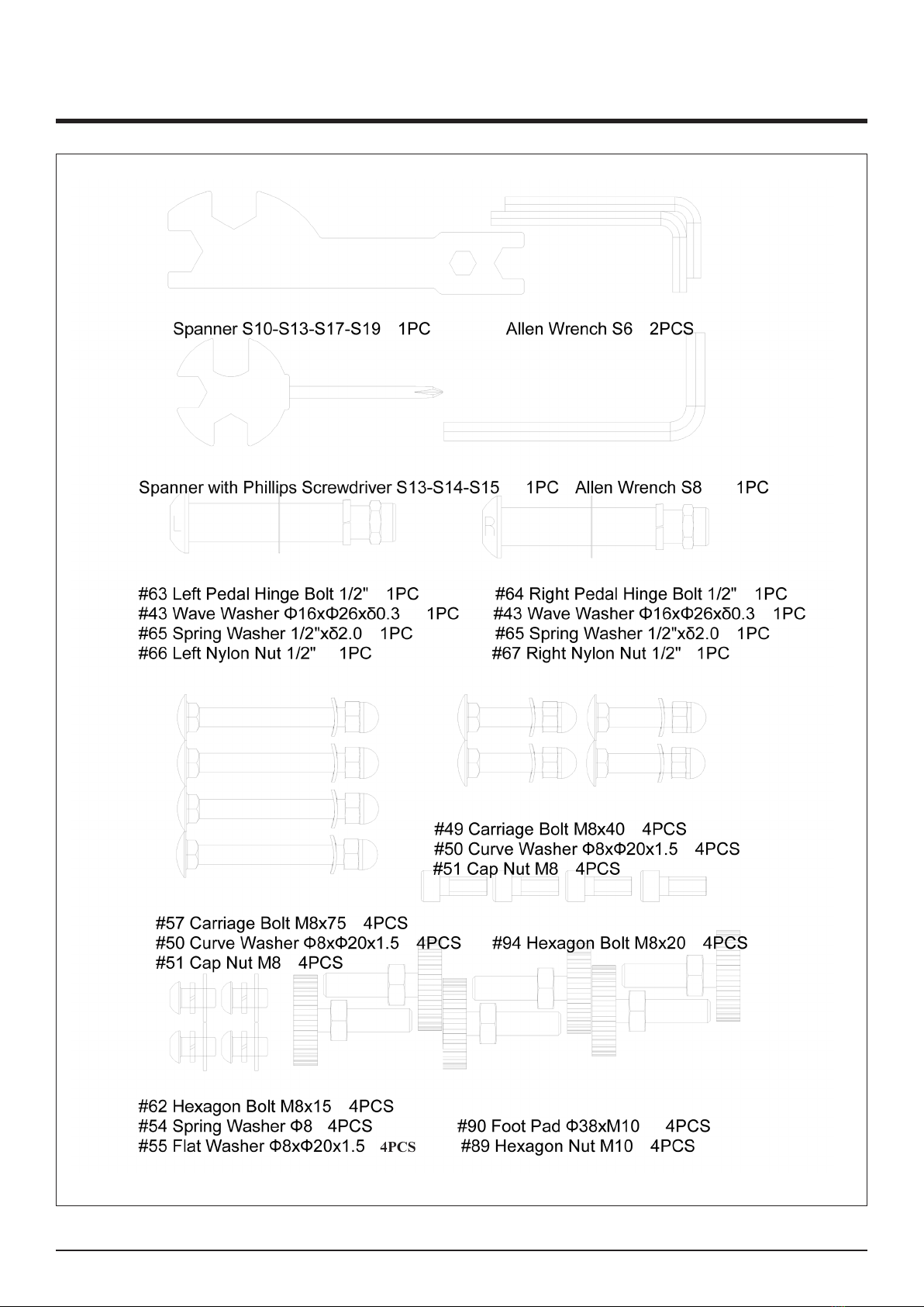
18 Left Foot Pedal 1 49 Carriage Bolt M8x40 4
19 Right Foot Pedal 1 50 Curve Washer Ф8xФ20x1.5 12
20 Aluminum Strip 500x25 2 51 Cap Nut M8 8
21 Belt Wheel Ф260 1 52 Handlebar End Cap Ф25 2
22 Axle 1 53 Ball End Cap Ф50 2
23 Belt PJ6/400 1 54 Spring Washer Ф8 4
24 Magnetic Wheel Ф260 1 55 Flat Washer Ф8xФ20x1.5 10
25 Left Crank 7.9” 1 56 Cross Pan Head Bolt ST4.6x16 1
26 Right Crank 7.9” 1 57 Carriage Bolt M8x75 4
27 Tension Cable L=800mm 1 58 Cross Pan Head Tapping Screw
ST4.2x20
2

5
ASSEMBLY INSTRUCTIONS
28 Tension Control Knob
L=585mm
1 59 Bush φ18*φ14*φ8*10 4
29 Flat Washer Ф520x1.0 1 60 Metal Bushing Ф28xФ16x16 8
30 Cross Pan Head Bolt M5x20 1 61 Bushing Ф15.8x50 4
31 Computer 1 62 Hexagon Bolt M8x15 14
63 Left Pedal Hinge Bolt 1/2" 1 86 Cross Pan Head Tapping Screw
ST4.2x25
7
64 Right Pedal Hinge Bolt 1/2" 1 87 Cross Pan Head Self-drilling Tap-
ping Screw ST4.2x25
8
65 Spring Washer 1/2"xδ2.0 2 88 Round End Cap for Rear Support
Frame Φ60
6
66 Left Nylon Nut 1/2" 1 89 Hexagon Nut M10 6
67 Right Nylon Nut 1/2" 1 90 Foot Pad Ф38xM10 6
68 Hexagon Bolt M8x20 1 91 Movable Wheel Φ61x50.5 2
69 Pressure Plate 1 92 Hexagon Bolt M6x15 4
70 Eye Bolt M8x50 1 93 Nylon Nut M6 4
71 Pressure Wheel Φ43x-
Φ34x24
1 94 Hexagon Bolt M8x20 4
72 Flat Washer Ф6xФ12xδ1.0 1 95 Bearing 6003Z 2
73 Cross Pan Head Screw
M6x12
1 96 Circlip Φ17 2
74 Nylon Nut M8 7 97 Wave Washer Ф22xФ17x0.3 1
75 Eye Bolt M6x36 2 98 Outer Hexagon Bolt M10x78 2
76 U-shape Bracket 2 99 Movable
77 Spring Washer Φ6 6 100 Bearing 6002 4
78 Hexagon Nut M6 2 101 WheelФ70 2
79 Flange Nut M10x1.0 2 102 Pan Head Inner Hexagonal Bolt
M8x40
2
80 Round End Cap Φ25 2 103 Rear Stabilizer 1
81 Connecting Plate for Foot
Pedal
2 104 Knob M12x65 1
82 Flat Washer Φ8xΦ16x1.5 4 105 Pan Head Inner Hexagonal Bolt
M8x55
2
83 Flange Nut M10x1.25 2 106 Plug for Square Tube 2
84 Crank Cover 1 2 107 Plug for Round Tube 2
85 Crank Cover 2 2
6
HARDWARE BAG

7
EXPLODED DIAGRAM
8
ASSEMBLY INSTRUCTIONS
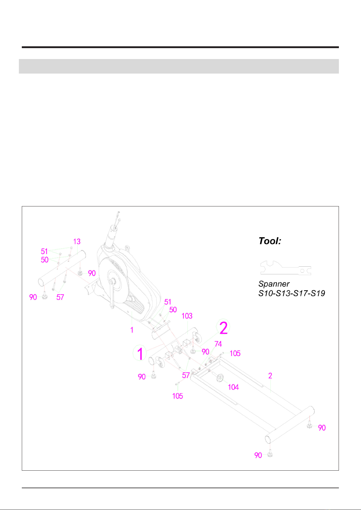
STEP 1 : Front Stabilizer and Rear Support Frame Installation
1. Attach Front Stabilizer (13) onto Main Frame (1) with two M8x75 Carriage Bolts (57), two
Ф8xФ20x1.5 Arc Washers (50), and two M8 Cap Nuts (51). Tighten and secure with Spanner
provided.
2. Attach two Ф38xM10 Foot Pads (90) to the Rear Support Frame (2).
3. In the same way to Attached four Ф38xM10 Foot Pads (90) to the Front Stabilizer (13) and
Rear Stabilizer (103).
4. Then Attach Rear Stabilizer(103) onto Main Frame (1) with two M8x75 Carriage Bolts (57), two
Ф8xФ20x1.5 Arc Washers (50), and two M8 Cap Nuts (51).Tighten and secure with Spanner
provided.
5. Attach Rear Support Frame (2) onto Rear Stabilizer (103) with twoM8x55 Pan Head Inner
Hexagon Bolt(105) and two M8 Stop nut (74).
6. Tighten and secure with Knob M12x65 (104)
9
ASSEMBLY INSTRUCTIONS
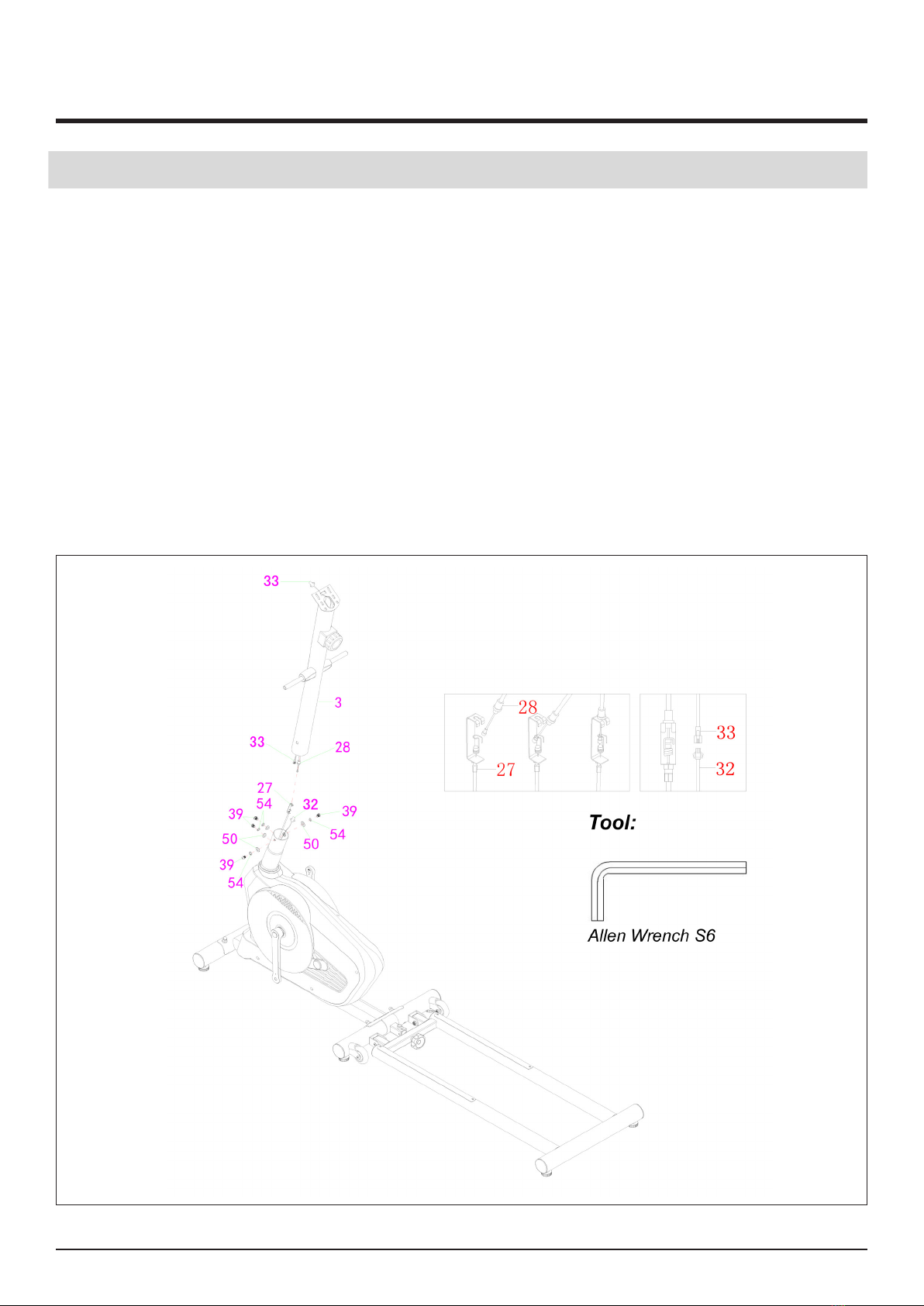
STEP 2 : Front Post Installation
1. Remove the pre-assembled six M8x15 Hexagon Bolts (39), six Ф8 Spring Washers (54), four
Ф8xФ20x1.5 Flat Washers (55) and four Ф8xФ20x1.5 Curve Washers (50) from the tube of
Main Frame (1) with Allen Wrench provided.
2. Connect Sensor Wire (32) and Extension Sensor Wire (33) together.
IMPORTANT: Turn the Tension Control Knob (28) to the Level 8.
3. Insert bottom of Tension Control Knob (28) into the cable lock of Tension Cable (27). Then pull
Tension Control Knob (28) upward and slide it into the slot of metal bracket of Tension Cable
(27). Then, lower Tension Control Knob (28) so that is sits on the metal bracket of Tension
Cable (27).
4. After properly connecting the tension cable assembly, attach Front Post (3) to the tube
of Main Frame (1) with six M8x15 Hexagon Bolts (39), six Ф8 Spring Washers (54), four
Ф8xФ20x1.5 Flat Washers (55) and four Ф8xФ20x1.5 Curve Washers (50) that were removed.
NOTE:Do not tighten the Hexagon Bolts (39), Spring Washers (54), Flat Washers (55) and Curve

10
ASSEMBLY INSTRUCTIONS
STEP 3 : Left & Right Handrails,Connection Assembly for Left & Right Foot
Bar and Left & Right Foot Bars Installation
1. Remove pre-assembled two M10x20 Hexagon Bolts (48), two Ф10 Spring Washers (47), two
Ф10xФ25x2.0 Big Washers (46) and two D-shaped Washers (45) from the Rotation Rod.
2. Slide Left Handrails & Connection Assembly for Left Foot Bar (5)(7),Right Handrails &
Connection Assembly for Right Foot Bar (6)(8) onto Rotation Rod with two M10x20 Hexagon
Bolts (48), two Ф10 Spring Washers (47), two Ф10xФ25x2.0 Big Washers (46) and two
D-shaped Washers (45) that were removed. Tighten and secure with two S6 Allen Wrenches.
3. Remove pre-assembled two Ф16xФ26x0.3 Wave Washers (43), two Connecting Plates for
Foot Pedal (81), four Ф8xФ20x1.5 Flat Washers (55), two Φ8xΦ16x1.5 Flat Washers (82), and
six M8x15 Hexagon Bolts (62) from Connection Assembly for Left & Right Foot Bars (7)(8).
4. Attach two Ф16xФ26x0.3 Wave Washers (43) onto Connection Assembly for Left & Right
Foot Bars (7)(8). Then, slide Left & Right Foot Bars (9)(10) on Connection Assembly for Left &
Right Foot Bars (7)(8).
5. Attach Connecting Plates for Foot Pedal (81) to Connection Assembly for Left & Right Foot
Bars (7)(8) with four Ф8xФ20x1.5 Flat Washers (55), two Φ8xΦ16x1.5 Flat Washers (82), and
six M8x15 Hexagon Bolts (62) that were removed. Tighten and secure with S6 Allen Wrench
provided.
6. Remove pre-assembled two 1/2”xδ2.0 Spring Washers (65), two 1/2” Left & Right Nylon Nuts
(66)(67) from two Left & Right Hexagon Bolts (63)(64).
7. Attach Left & Right Foot Bars (9)(10) to Left & Right Cranks (25)(26) with two Left & Right
Hexagon Bolts (63)(64), two Ф16xФ26x0.3 Wave Washers (43), two 1/2”xδ2.0 Spring Washers
8. (65) and two 1/2” Left & Right Nylon Nuts (66)(67). Tighten and secure with S8 Allen Wrench
and Spanner provided.
IMPORTANT: Turn the Left Hexagon Bolt (63) COUNTER-CLOCKWISE as tightly as you can.
Secure by tightening Left Nylon Nut (66) CLOCKWISE.
9. Turn the Right Hexagon Bolt (64) CLOCKWISE as tightly as you can. Secure by tightening
Right Nylon Nut (67) COUNTER-CLOCKWISE.
10.Make sure the movable wheels on Left & Right Foot Bars (9)(10) are in the middle of the sliding
rails on Rear Support Frame. Then, secure and tighten Hexagon Bolts (39), Spring Washers
(54), Flat Washers (55) and Curve Washers (50) on Front Post (3) with S6 Allen Wrench.

11
ASSEMBLY INSTRUCTIONS
STEP 3 : Left & Right Handrails,Connection Assembly for Left & Right Foot
Bar and Left & Right Foot Bars Installation
12
ASSEMBLY INSTRUCTIONS
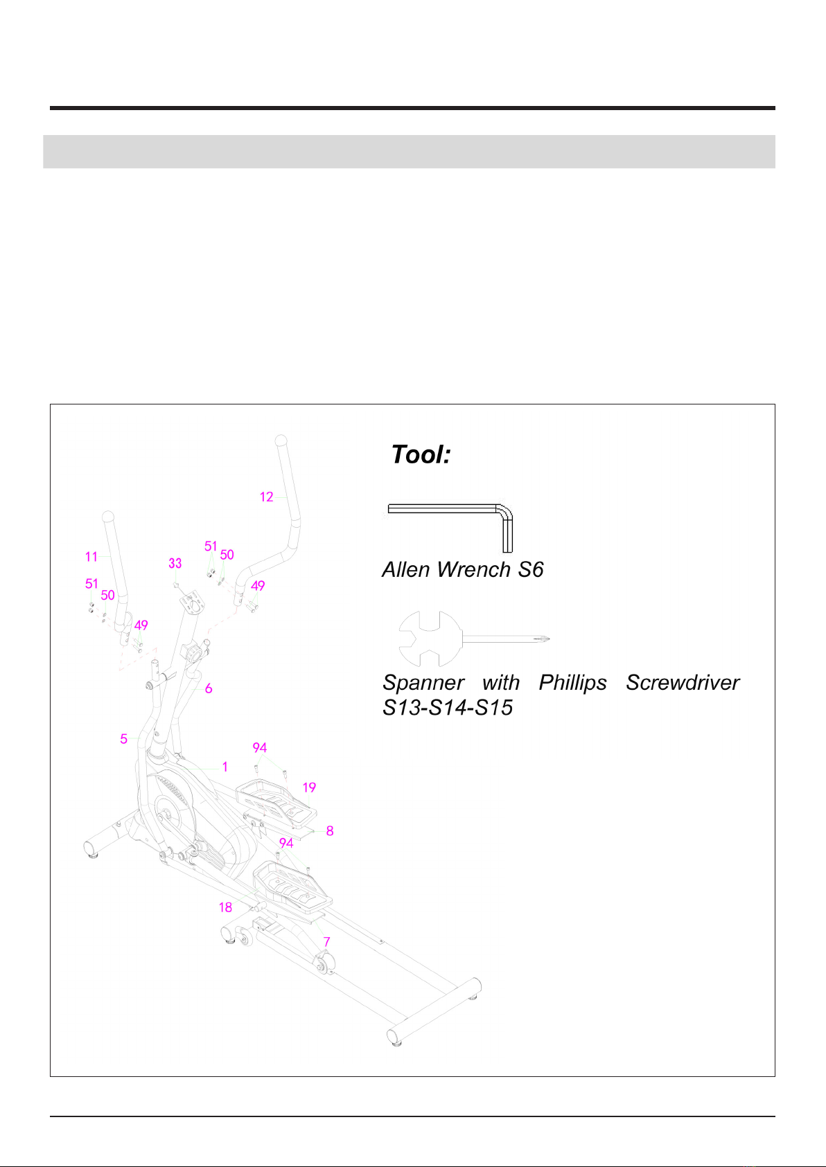
STEP 4 : Left & Right Handlebars and Left & Right Foot Pedals Installation
1. Insert the Left & Right Handlebars (11)(12) into the tube of Left & Right Handrails (5)(6) with
four M8x40 Carriage Bolts (49), four Ф8xФ20x1.5 Curve Washers (50), and four M8 Cap
Nuts (51). Tighten and secure with Spanner with Phillips Screwdriver and S6 Allen Wrench
provided.
2. Remove pre-assembled four M8x20 Hexagon Bolts (94) from Connection Assembly for Left &
Right Foot Bars (7)(8).
3. Attach Left & Right Foot Pedals (18)(19) onto the Connection Assembly for Left & Right Foot
Bars (7)(8) with four M8x20 Hexagon Bolts (94) that were removed. Tighten and secure with
S6 Allen Wrench.
13
ASSEMBLY INSTRUCTIONS
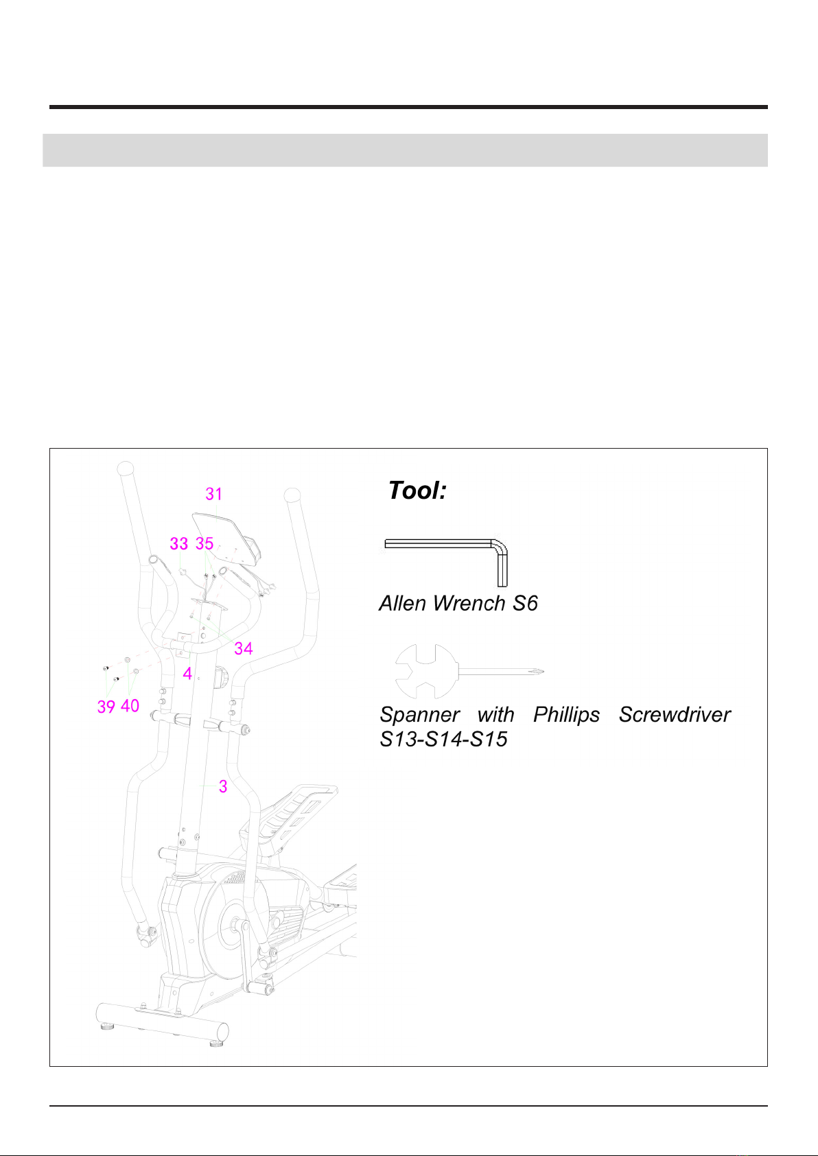
STEP 5 : Fixed Handlebar and Computer Installation
1. Remove pre-assembled two M5x10 Cross Pan Head Bolts (34) from Computer (31) and two
M8x15 Hexagon Bolts (39) and two Ф8xФ16x1.5 Curve Washers (40) from Front Post (3).
2. Insert the Wires for Hand Pulse Sensor (35) into Front Post (3) and then pull them out from the
top end of Front Post (3).
3. Attach the Fixed Handlebar (4) onto the plate of Front Post (3) with two M8x15 Hexagon Bolts
4. (39) and two Ф8xФ16x1.5 Curve Washers (40) that were removed. Tighten and secure with S6
Allen Wrench.
5. Connect Extension Sensor Wire (33) and Hand Pulse Sensor with Wires (35) to the wires that
6. come from Computer (31). Tuck wires into Front Post (3). Attach Computer (31) onto the top
of Front Post (3) with two M5x10 Cross Pan Head Bolts (34) that were removed. Tighten and
secure with Spanner with Phillips Screwdriver.

14
ASSEMBLY INSTRUCTIONS
Folding Illustration
1. Screw o the Knob (104), fold the Rear Support Frame (2) as above photo, then tighten and
secure with Knob (104).

15
MAINTENANCE
CLEANING
The bench can be cleaned with a soft clean damp cloth.Do not use abrasives or solvents on plastic parts.
Please wipe your perspiration o the bench after each use.Be careful not get excessive moisture
on the computer display panel as this might cause an electrical hazard or electronics to fail.
Please keep the bench, especially the computer console out of direct sunlight to prevent screen
damage.
Please inspect all assembly bolts and pedals on the machine for proper tightness every week
STORAGE
Store the bench in a clean and dry environment away from children.
TROUBLESHOOTING
PROBLEM SOLUTION
There is no display on the computer
console.
1. Remove the computer console and verify
the wire that comes from the computer
console is properly connected to the wire
that comes from the handlebar post.
2. Check if the batteries are correctly
positioned and battery springs are in
proper contact with batteries.
3. The batteries in the computer console
may be dead. Change to new batteries.
The bench wobbles when in use Turn the rear stabilizer end cap on the rear
stabilizer as needed to level the magnetic
bike.
The bench makes squeaking noise when in
use.
The bolts may be loosen on the bench.
Please inspect all of the bolts and tighten any
loosen bolts.

16
WARM UP AND COOL DOWN ROUTINE
Using your AB TOWER will provide you with several benets, it will improve your physical tness, tone
muscle and in conjunction with a calorie controlled diet help you lose weight. The WARM-UP is an
important part of any workout. The purpose of warming up is to prepare your body for exercise and to
minimize injuries. Warm up for two to ve minutes before aerobic exercising.It should begin every session
to prepare your body for more strenuous exercise by heating up and stretching your muscles, increasing
your circulation and pulse rate, and delivering more oxygen to your muscles.
COOL DOWN at the end of your workout, repeat these exercises to reduce soreness in tired muscles. The
purpose of cooling down is to return the body to its resting state at the end of each exercise session. A
proper cool-down slowly lowers your heart rate and allows blood to return to the heart.
HEAD ROLLS
Rotate your head to the right for one count,
you should feel a stretching sensation up the
left side of your neck. Then rotate your head
back for one count, stretching your chin to the
ceiling and letting your mouth open. Rotate
your head to the left for one count, then drop
your head to your chest for one count.
SHOULDER LIFTS
Lift your right shoulder toward your ear for one
count. Then lift your left shoulder up for one
count as you lower your right shoulder.
SIDE STRETCHES
Open your arms to the side and lift them until
they are over your head. Reach your right arm
as far toward the ceiling as you can for one
count. Repeat this action with your left arm.

17
WARM UP AND COOL DOWN ROUTINE
QUADRICEP STRETCH
With one hand against a wall for balance, reach
behind you and pull your right foot up.Bring
your heel as close to your buttocks as possible.
Hold for 15 counts and repeat with left foot.
INNER THIGH STRETCH
Sit with the soles of your feet together and
your knees pointing outward. Pull your feet as
close to your groin as possible. Gently push
your knees toward the oor. Hold for 15 counts.
TOE TOUCHES
Slowly bend forward from your waist, letting
your back and shoulders relax as you stretch
toward your toes.Reach as far as you can and
hold for 15 counts.
HAMSTRING STRETCHES
Extend your right leg. Rest the sole of your
left foot against your right inner thigh. Stretch
toward your toe as far as possible. Hold for 15
counts.Relax and then repeat with left leg.
CALF/ACHILLES STRETCH
Lean against a wall with your left leg in front of
the right and your arms forward.Keep your right
leg straight and the left foot on the oor; then
bend the left leg and lean forward by moving
your hips toward the wall.Hold, then repeat on
the other side for 15 counts.

18
FIT4HOME LTD
Fit4Home is essentially an online business which aims to provide high quality
Exercise and Fitness products to ensure all customers maintain a healthy lifestyle.
At Fit4Home we stock various dierent types of tness and exercise equipment
such as Treadmills, Cross Trainers, Weights, Exercise Bikes etc and aim to provide
an excellent service to each and every one of our valued customers. We try to cater
for every type of individual, so if you are someone who is very serious about health
and tness we can provide you with professional heavy duty products, but if you are
someone who is busy and short on space we can provide you with equipment that is
compact and aesthetically pleasing.
Fit4Home employs a dedicated customer service team to ensure the consumer is
provided with the best service and experience. For any queries or issues feel free to
contact us via e-mail or phone.
As an online business we sell our products independently via our website, and we
also trade from established markets such as Amazon and EBay. As an established
business we endeavour to earn the condence of the customer, it is for this reason
that we try our utmost best to dispatch products the same day using a next working
day delivery service to all UK mainland areas.
Along with the customer service department, Fit4Home consists of hard-working
and reliable technicians and designers who aim to meet the needs of our customers.
We oer a market leading 12 month warranty, which is simple and hassle free.
Fit4Home© Ltd
Hours of Business: 9am - 5pm
Website: www.t4home.co.uk
E-mail: customerservices@t4home.co.uk

19
Declaration of Conformity
We, Importer
Fit4home Ltd
Unit A, Perseverance Mills, Olive Lane, Darwen BB3 3DQ United Kingdom
Declare that the product
Front Drive Eliptical Trainer KPR65714
Complies with the following European Directives:
Stationery training equipment EN ISO 20957-1:2013
EN ISO 20957-5:2016+A1:2019
Authorised Signatory and technical le holder
Signed for and behalf of:
Fit4home Ltd
Unit A
Perseverance Mills
Olive Lane
Darwen
BB3 3DQ
United Kingdom
Tassadaq Hussain

20
This manual suits for next models
1
Table of contents
Other Fit4Home Fitness Equipment manuals

Fit4Home
Fit4Home TF-1109 User manual

Fit4Home
Fit4Home MAXX1 TF-7005A User manual

Fit4Home
Fit4Home TF-WB1007 User manual

Fit4Home
Fit4Home TF-WB501001 User manual

Fit4Home
Fit4Home TF-1001 User manual

Fit4Home
Fit4Home TF-306A User manual

Fit4Home
Fit4Home TF-7512 User manual

Fit4Home
Fit4Home KPR91220 ROWER User manual

Fit4Home
Fit4Home TF-7102A User manual
Popular Fitness Equipment manuals by other brands


G-FITNESS
G-FITNESS AIR ROWER user manual

CAPITAL SPORTS
CAPITAL SPORTS Dominate Edition 10028796 manual

Martin System
Martin System TT4FK user guide

CIRCLE FITNESS
CIRCLE FITNESS E7 owner's manual

G-FITNESS
G-FITNESS TZ-6017 user manual

Accelerated Care Plus
Accelerated Care Plus OMNISTIM FX2 CYCLE/WALK user manual


