Fit4Home MAXX1 TF-7005A User manual
1
5T-B0C3-VZLBPlease Keep For Future Reference
IMPORTANT - Please Read Instructions Fully Before Assembly Or Use
These instructions contain important information which will help you get the best
from your equipment and ensure safe and correct assembly, use and maintenance.
If you need help or have damaged or missing parts,
call the Customer Helpline: 0330 124 0718 (Opening hours: Mon-Fri 9:00am-3:00pm)
or Email: customerservices@fit4home.co.uk
MAXX1 TF-7005A
USER MANUAL

2
CONTENTS
Safety Information
Parts Chart
Parts List
Assembly Instructions
Step 1
Step 2
Step 3
Step 4
Step 5
Step 6
Step 7
Step 8
Step 9
Step 10
Step 11
Step 12
Declaration
03-04
05-06
07
08-24
08
09
10
11
12
13
14
15-16
19-20
21
22-23
24
25

3
SAFETY INFORMATION
Be sure to read the entire instruction manual before you assemble or use this
equipment. Particularly, note the following safety precautions.
• Exercising. Do not wear loose clothing that could get caught in the equipment. Appropriate
footwear is also required when using the equipment.
• Use the equipment only for intended use, as described in this instruction manual. Do not use
attachments that is not recommended by the manufacturer.
• Disabled people should not use the equipment without a qualied instructor or doctor
present.
• Never operate or use the equipment if it is damaged or not functioning properly.
• Examine the equipment frequently especially the easily damaged parts. The safety
level of the equipment can only remain if it is examined regularly. Replace any damaged
components immediately. Do not use the equipment until it has been fully repaired.
• Parents and others responsible for children must be aware that playing on the equipment
could be dangerous and could lead to injuries. Children must not be left unattended with the
exercise equipment.
• A spotter is recommended whilst doing exercise, therefore to prevent any injuries.
• This product is suitable for a maximum user weight of 100kg.
• Your product is intended for use in clean and dry conditions. You should avoid storage in
cold and damp places as this could lead to corrosion and other similar problems that are
outside of our control.
IMPORTANT SAFETY INFORMATION

4
INSTRUCTIONS WHEN ASSEMBLING
• Check you have all the components and tools listed in the instruction manual.
• Remove all ttings from the plastic bags and separate them into dierent groups.
• Keep children and animals away from the work area, (small components can causechoking if
swallowed).
• Make sure you have enough space to layout the parts before starting.
• The assembly of this equipment is best to carried out by more than one person.
• Assemble the item as close to its nal position (in the same room) as possible.
• The free-standing equipment shall be installed on a stable and level base.
• Dispose of all packaging carefully and responsibly.
Please note that you will have to retain the outer packaging in case you may need to return
the item.
IMPORTANT SAFETY INFORMATION
INSTRUCTIONS WHEN USING
• Do not use the equipment near water or anywhere outdoors.
• Keep unsupervised children and pets away from the equipment at all times. Also donot leave
children unattended in the same room with the equipment.
• Injuries to health may result from incorrect or excessive training.
• Before using the equipment to exercise, always warm up with stretching exercise to prevent
any injuries or muscle pains.
• This product is only intended for domestic use.
• If the user experiences any abnormal symptoms STOP the workout and CONSULT A
DOCTOR IMMEDIATELY.
• Only one person at a time should use the equipment.
• Keep hands away from moving parts at all times.
• Always wear appropriate workout clothing when using the equipment
5
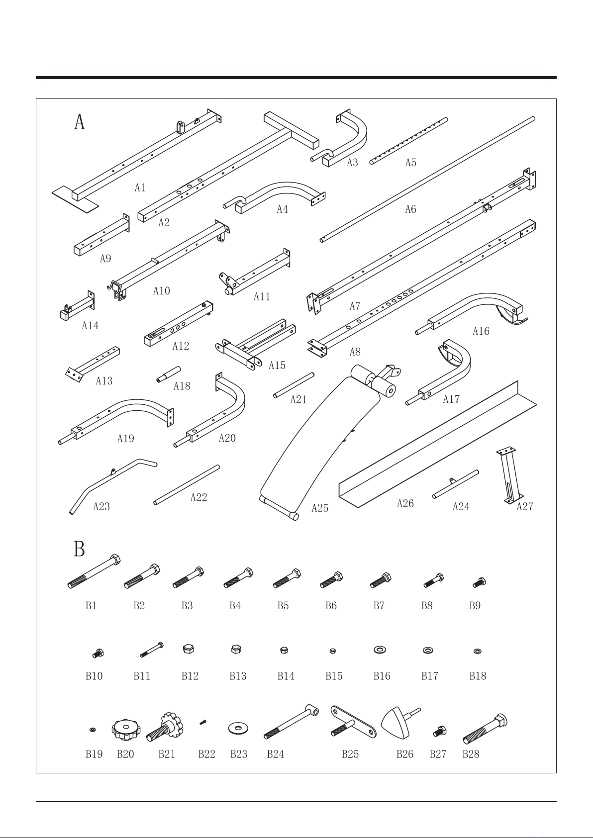
PARTS LIST

6
PARTS LIST

7
PARTS LIST
8
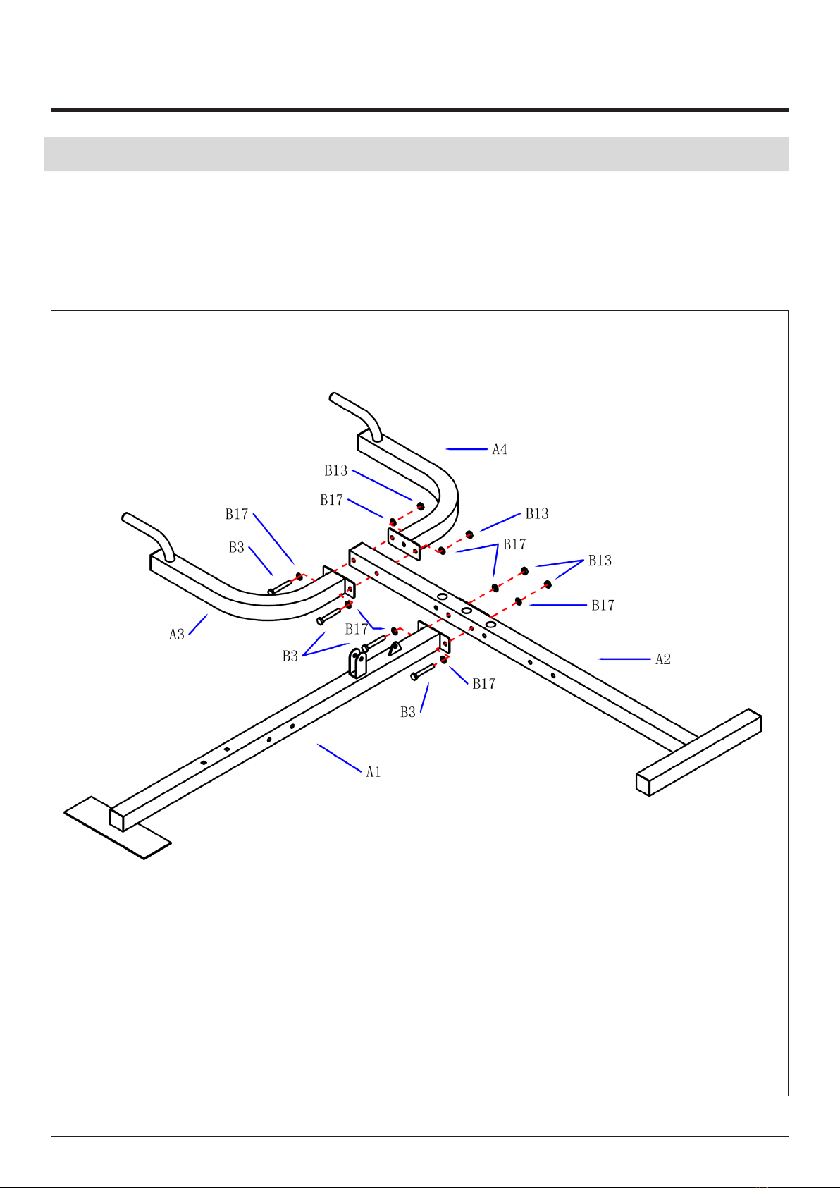
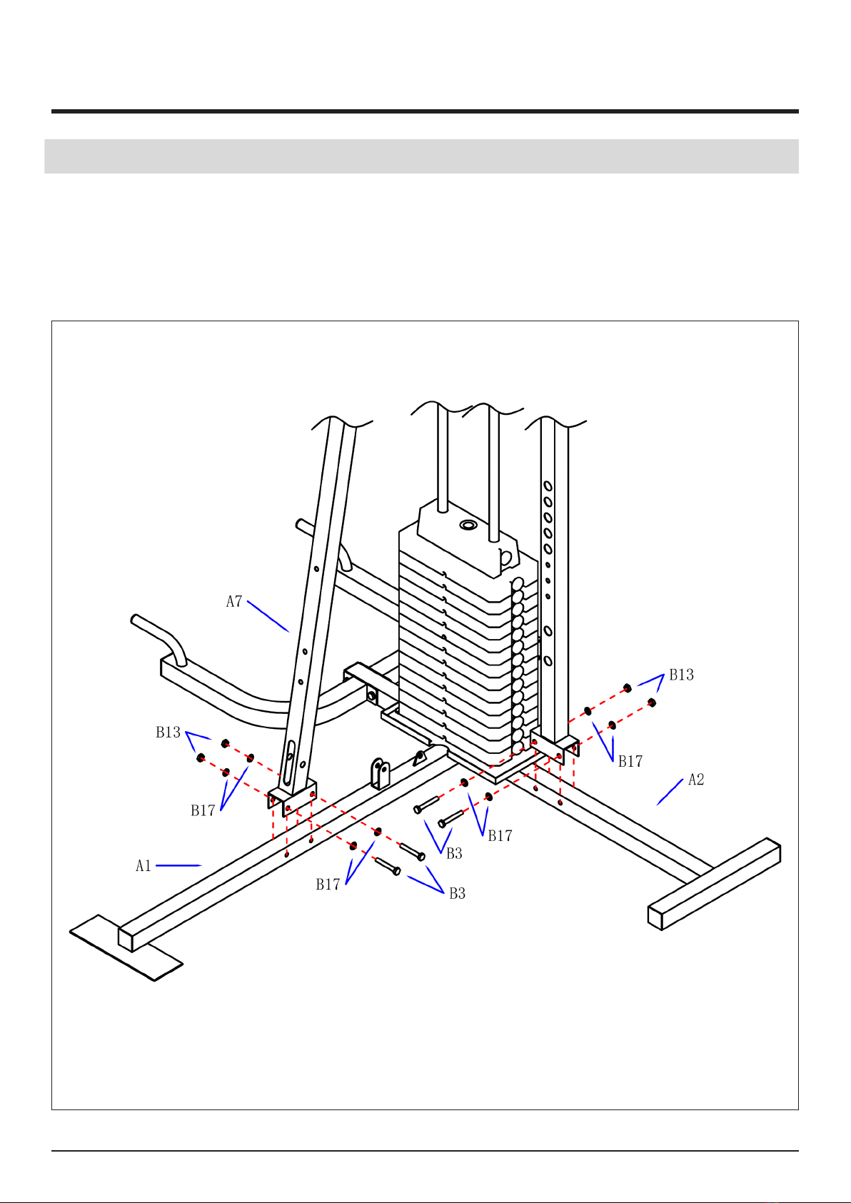
STEP 1
1. The straight bottom tube (A1) is connected to the transverse bottom tube (A2). Use bolt (B3)
washer (B17) and nut (B13).
2. The left bottom bend pipe (A3) is connected with the right bottom tube (A4) to the
transverse bottom tube (A2). Use washer (B17) bolts (B3) and nuts (B13).
ASSEMBLY INSTRUCTIONS
9
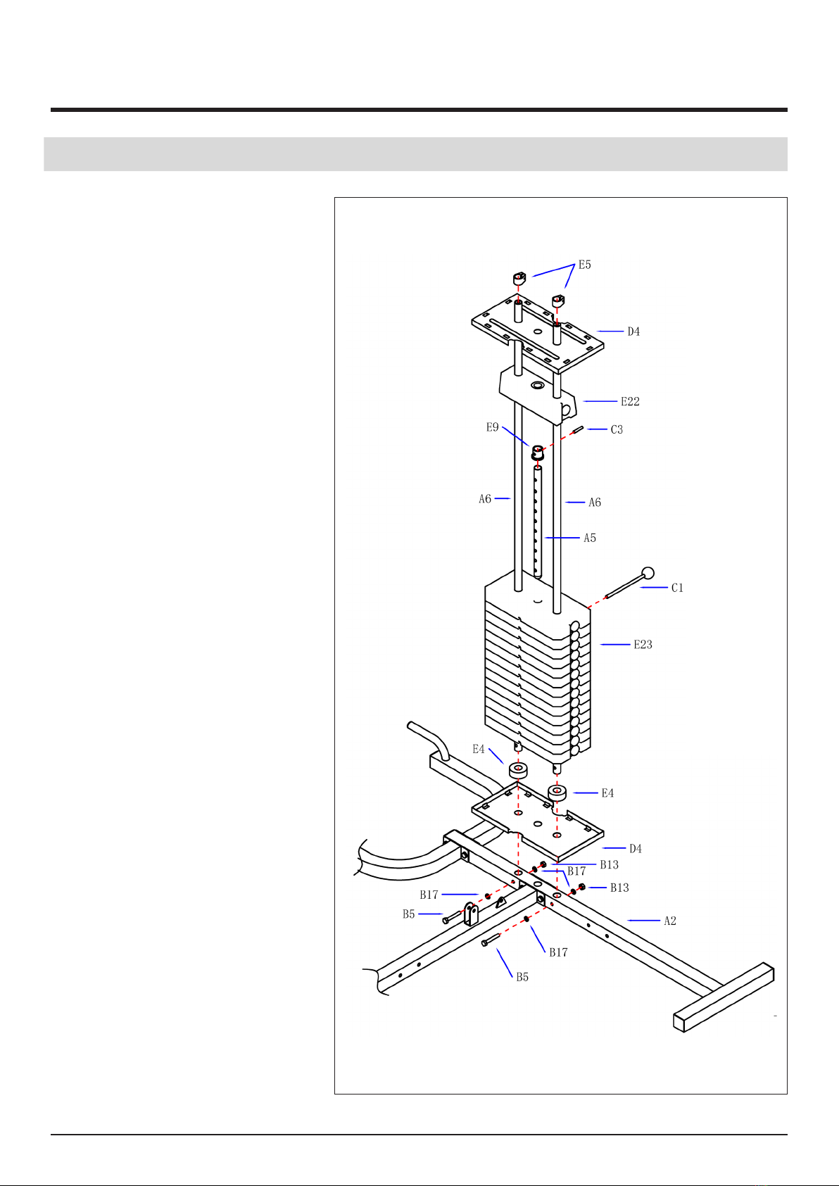
STEP 2
1. The two guide rods (A6) are
inserted into the transverse
bottom tube (A2) through the
protective net cover frame.
Use two rubber washer (E4)
washer (B17) bolts (B5) and
nuts (B13).
2. The counterweight block
(E23) penetrates into the
guide rod (A6).
3. The weight selection
lever (A5) inserted into
the counterweight block
(E23). and then install the
positioning sleeve (E9) pin
(C3) and counterweight top
block (E22).
4. The protective net cover
frame (D4) penetrates into
the guide rod (A6).Then x the
locating ring (E5).
ASSEMBLY INSTRUCTIONS
10
STEP 3
1. Connecting the middle column (A7) to the straight bottom pipe (A1).Usewasher (B17) bolts
(B3) and nuts (B13).
2. Connect the side bracket (A8) to the long transverse bottom tube (A2). Use washer (B17)
bolts (B3) and nuts (B13).
ASSEMBLY INSTRUCTIONS
11
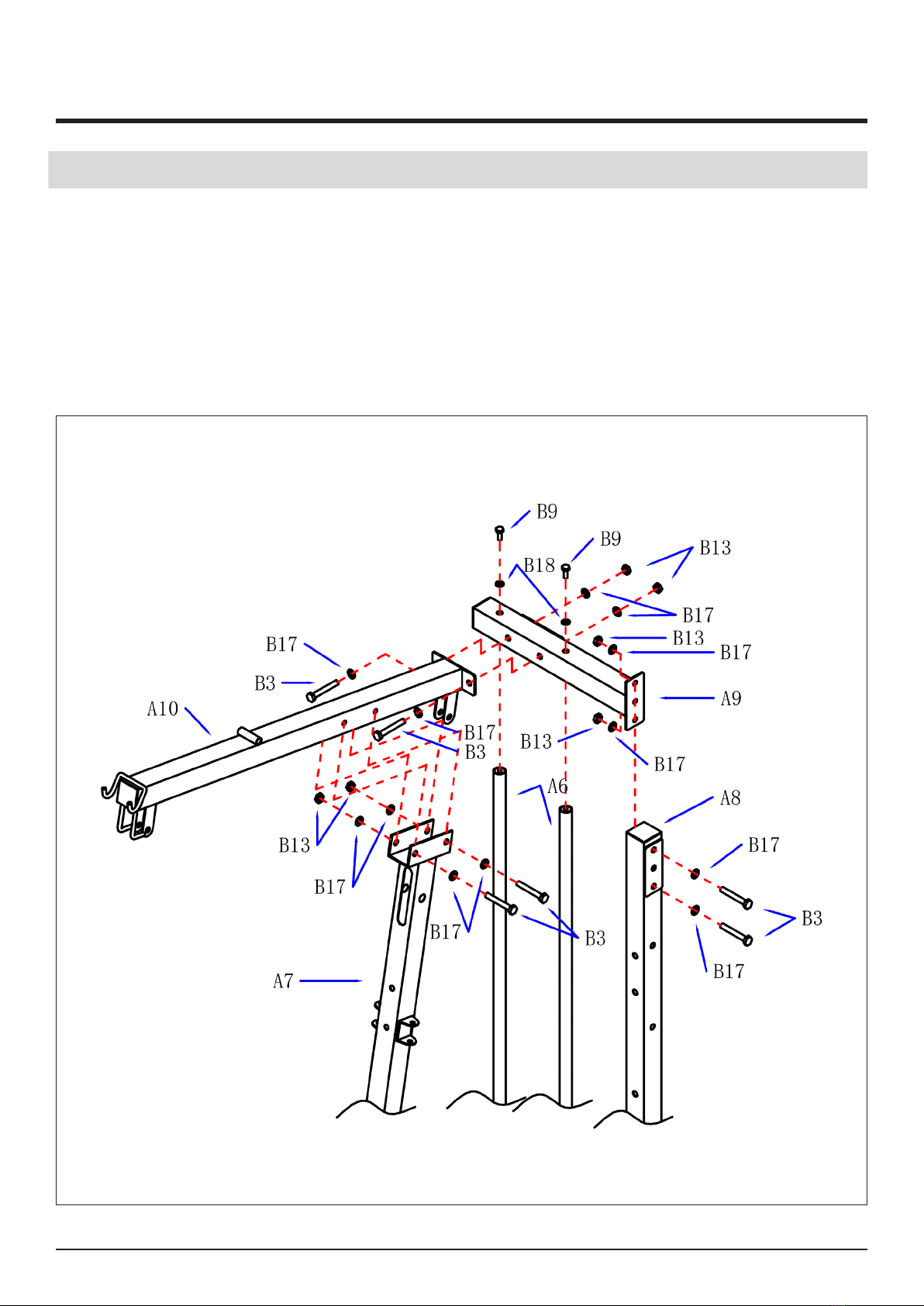
STEP 4
1. The upper connecting pipe (A9) is installed on the 2 guide rods (A6).Use washer (B18) bolt
(B9).Connected to Ce Lizhu (A8), Use washer (B17)bolts (B3) and nuts (B13).
2. Install upper bracket (AlO) on the middle column (A7),Use washer (Bl7)bolts (B3) and nuts
(B13).Then the upper bracket (A10) is connected to the upper connecting pipe (A9), Use
washer (B17) bolts (B3) and nuts (B13).
ASSEMBLY INSTRUCTIONS
12
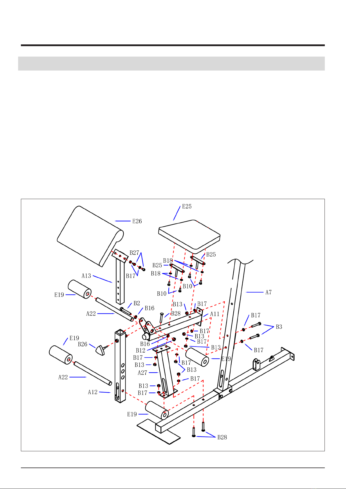
STEP 5
1. The seat tube (A11) installed in the column (A7).Use washer (B17) bolts (B3) and nuts (B13)
2. The seat cushion connecting frame (B25) installed in the seat tube (A11). Use washer (B17) and nut
(B13).
3. Install the support tube (a27) between the seat cushion tube (a11) and the straight bottom tube (A1)
and secure with washer (B17), carriage bolt (B28) and nut (B13)
4. The seat cushion (E25) installed in the connecting frame (B25) on.Use washer(B18) and bolt (B10).
5. Will kick tube (A12) mounted to the seat tube (A11), Use washer (B16) bolts (B2) and nuts (B12).
6. Two head muscle pad metal stent (A13) inserted into the skirting tube (A12) in. Fixed with knob (B26).
7. The two head pad (E26) is attached to the two head pad metal stent (A13),Use washer (B17) bolt
(B27).
8. The foam tube (A22) inserted into the seat tube (A11) and (A12) on the front kick. Then insert the 4
foam (E19).
ASSEMBLY INSTRUCTIONS
13
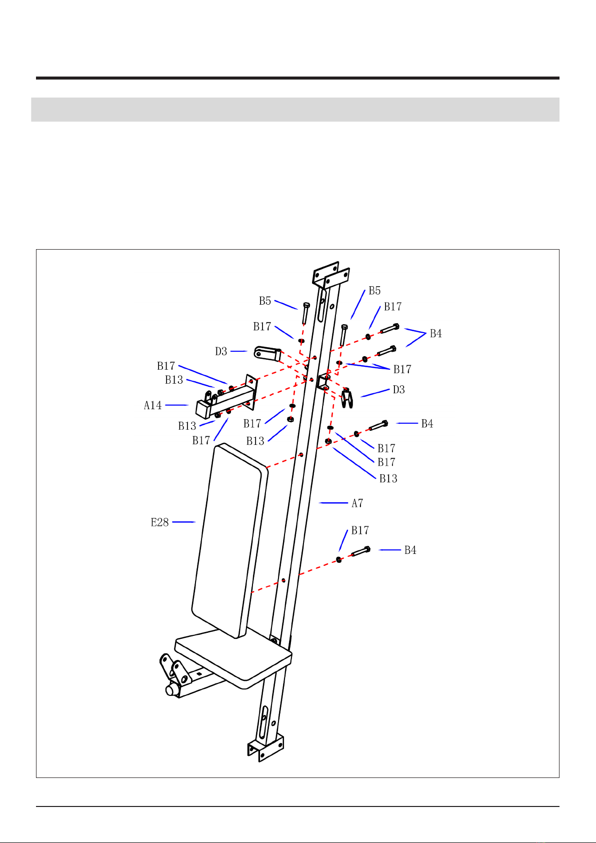
STEP 6
1. The small support (A14) installed in the middle column (A7). Use washer (B17) bolts (B4) and
nuts (B13).
2. The single pulley block (D3) installed in the middle column (A7).Use washer (B17) bolts (B5)
and nuts (B13).
3. The back pad (E28) installed in the middle column (A7). Use washer (B17) bolt (B4).
ASSEMBLY INSTRUCTIONS

14
STEP 7
1. Insert the Bearing(C2) to the chest press (A15) and the Upper barcket(A10),xed them by
bolt(B1), washer(B16),nut(B12).
2. Install the adjusting screw (B24) on the middle column cross member(A7).Use screw (B8)
nut(B14) and washer (B23) knob (B20).
3. The rocker (A16 and A17) installed on the chest press machine (A15).Use the powder
bearing (C2) washer (B16) screw (B2) and nut (B12).
4. The foam liner (E20) (E6) (E8) and a handle sleeve tube inserted rocker (A16 and A17).
5. The handle (A18) inserted rocker (A16 and A17) tube.Use washer (B18) and screw (B10).
ASSEMBLY INSTRUCTIONS
15
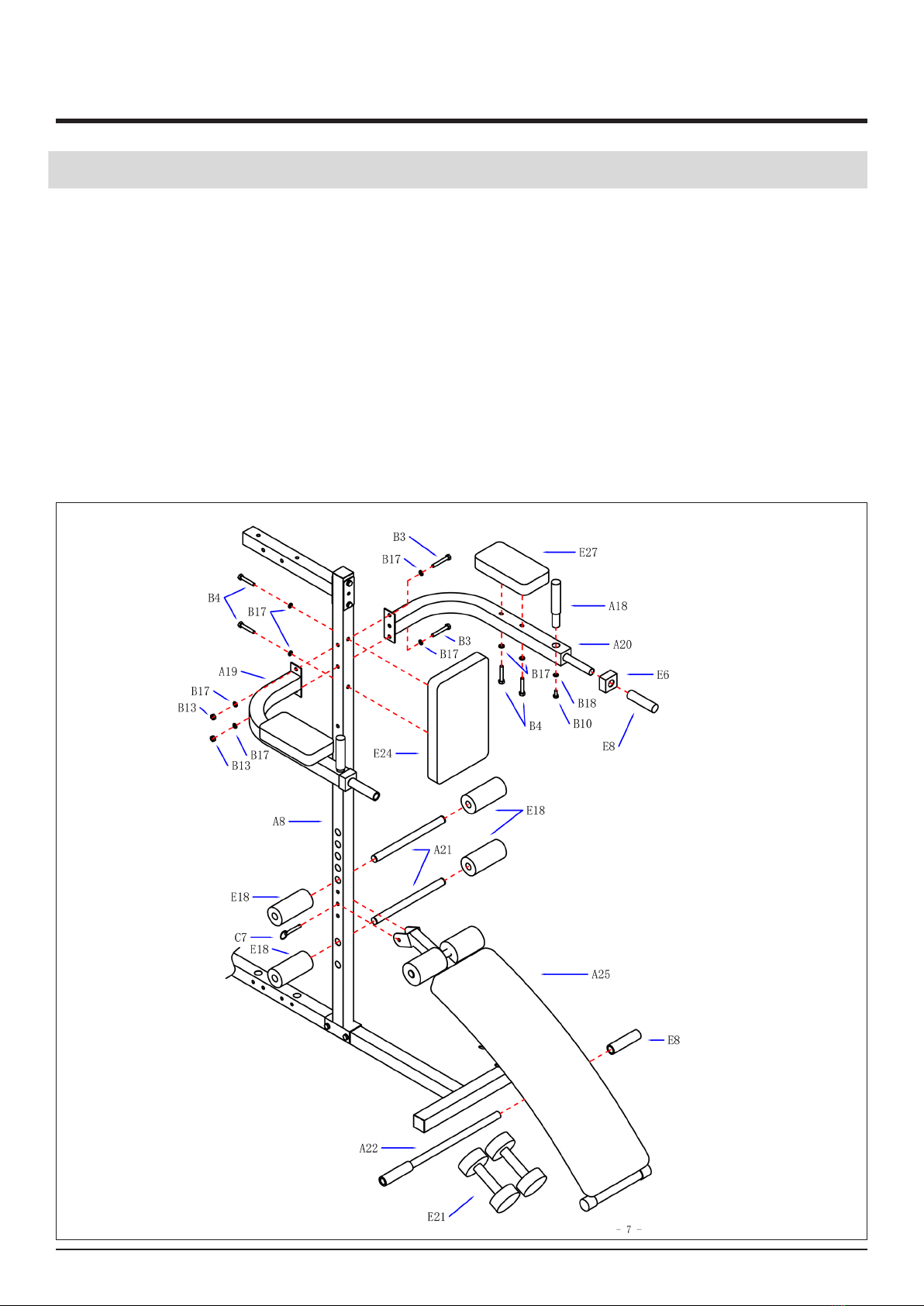
STEP 8
1. The support arm (A19 and A20) connected to Ce Lizhu (A8).Use washer (B17) bolts (B3) and
nuts (B13).
2. The small back pad (A24) needs to be installed on vertical frame 2 (A8). To secure use 2
washers (B17) and 2 screw bolts (F1).
3. The elbow pad (E27) mounted to the support arm (A19 and A20).Use washer (B17) bolt(B4).
4. The handle (A18) inserted into the supportarm (A19 and A20).Use washer (B18) bolt (B10)
Then install the liner (E6) and the handle (E8).
5. Connection on board (A25) using ball pin (C7).
6. The foam tube (A21) into the side column (A8) in. Install foam (E18).
7. The long foam tube (A22) installed in the supine position (A25) on board, Then install E8 the
handle sleeve (E8) and the dumbbell(E21).
ASSEMBLY INSTRUCTIONS

16
ASSEMBLY INSTRUCTIONS
17
ASSEMBLY INSTRUCTIONS

18
ASSEMBLY INSTRUCTIONS
19
ASSEMBLY INSTRUCTIONS
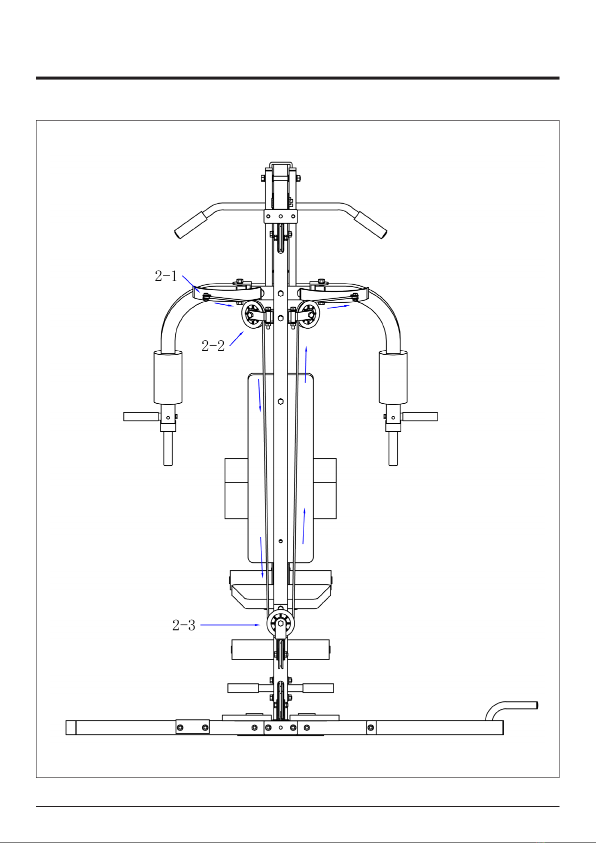
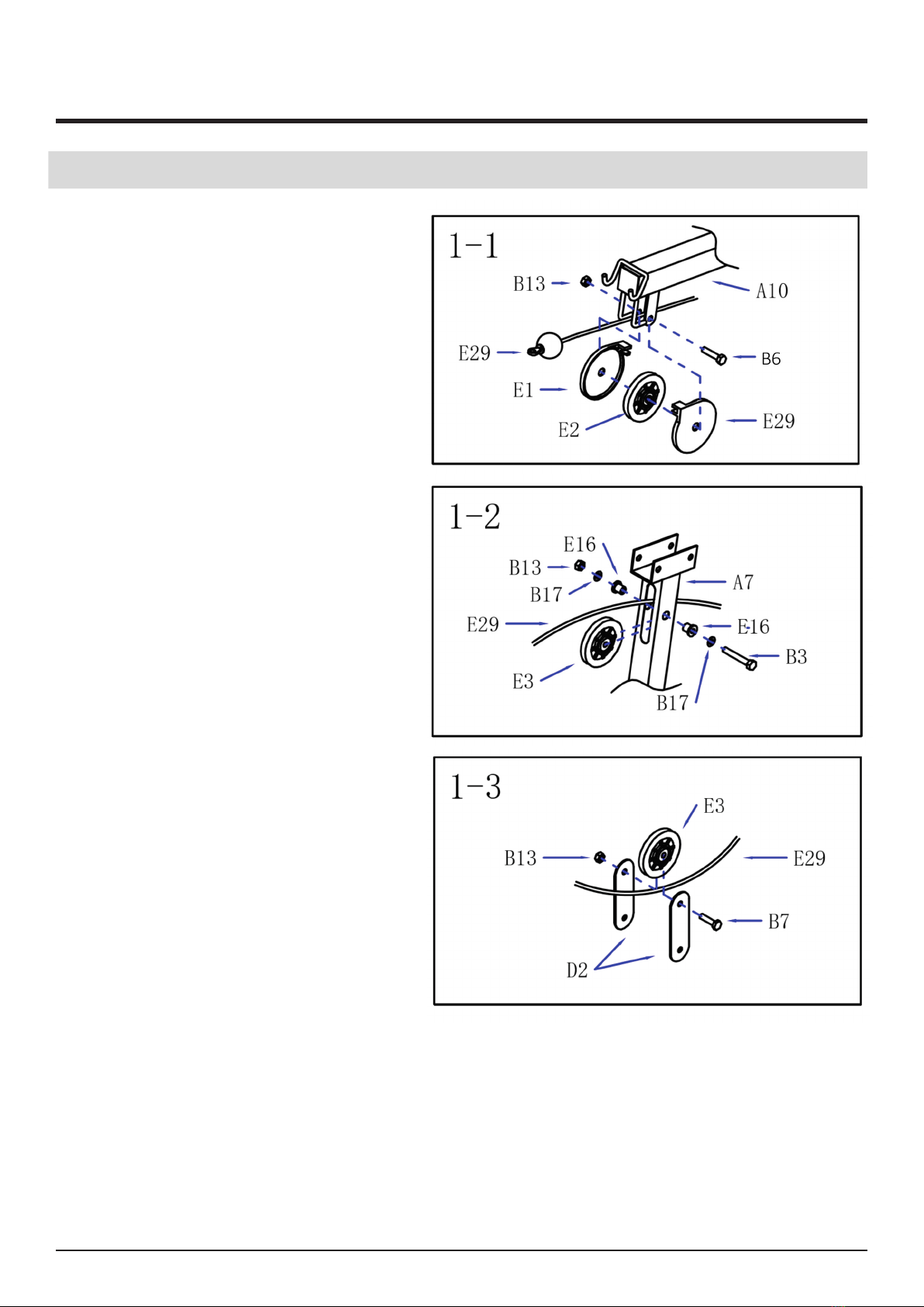
STEP 9
1. The upper wire rope (E29) through
the 1-1 pulley, Install pulley and pulley
cover (E2) (E29.)Use bolt (B6) nut
(B13).
2. And then through the 1-2 pulley
frame,Use of the pulley (E3) and the
sleeve (E16),Washer (B17) bolts (B3)
and nuts (B13).
3. And then through the 1-3 pulley
block, Installation and connection of
iron (D2) and block (E3). Use bolts (B7)
and nuts (B13).

20
ASSEMBLY INSTRUCTIONS
STEP 9
4. And then through the 1-4 pulley frame.
Use pulley (E3) bolts (B7) and nuts
(B13).
5. And then installed on the 1-5
combination.Use washer (B23) weight
block top block (E22) weight block
(E23) selector lever (A5).
Table of contents
Other Fit4Home Fitness Equipment manuals

Fit4Home
Fit4Home TF-306A User manual

Fit4Home
Fit4Home KPR65714 User manual

Fit4Home
Fit4Home TF-WB1007 User manual

Fit4Home
Fit4Home TF-1109 User manual

Fit4Home
Fit4Home TF-WB501001 User manual

Fit4Home
Fit4Home TF-7512 User manual

Fit4Home
Fit4Home KPR91220 ROWER User manual

Fit4Home
Fit4Home TF-7102A User manual

Fit4Home
Fit4Home TF-1001 User manual


