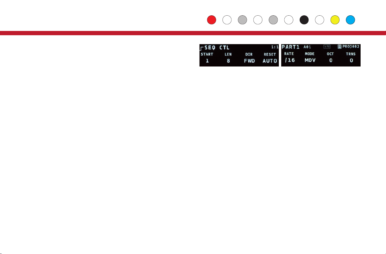
START, LEN:Sets the starting step and pattern length within the maximum
sequence length for the part.
DIR:Sets the sequence direction: Forwards, backwards, alternate with or
without repeating the ends, or run randomly.
RESET:Sets the sequence to reset automatically, every n beats, or
externally (EXT). For external reset, see Tips & Tricks on page 25.
RATE, MODE:The default rate for sequences is set using common musical
divisions (MDV), but there are several alternate modes:
MDV : Musical Division X16, X8T, X8 : Crossfade modes
PCT : % of a beat P16, P8T, P8: Phase modes.
SPD : Speed, higher is faster. 1/1 - 16/16 : Fractions of a beat.
The X and P modes are phase-based, where the rate deviates (faster or
slower) from a default rate of 16th, 8th note triplets or 8th notes. The X
modes have a wider range than the P modes.
OCT, TRANS:Add an octave or semitone transposition to all notes.
TIP: On the Seq Ctl page, the mini keyboard can be used to set the
transposition. Use Prev and Next to shift the keyboard down or up an
octave.
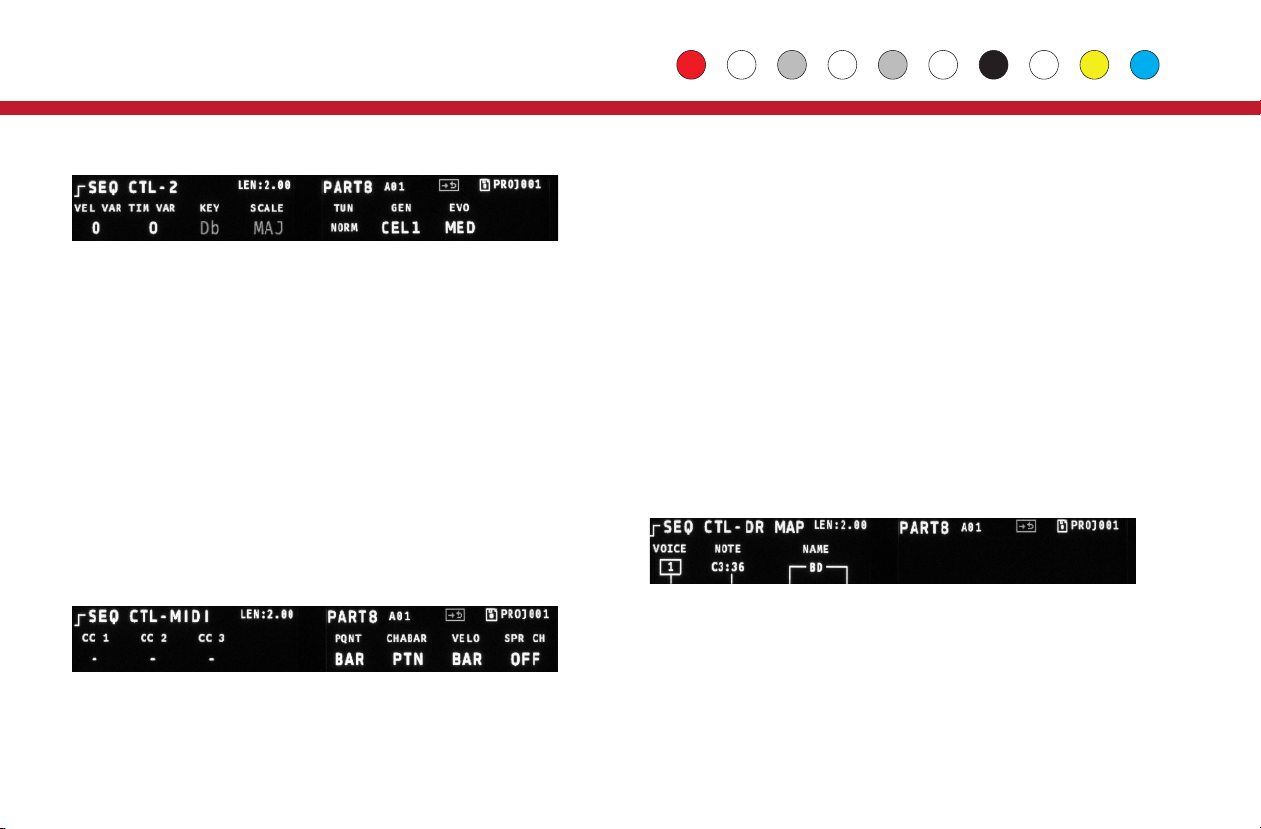
Sequence Controls: Page 2
VEL VAR, TIM VAR:Add random variations to Velocity and Timing
(groove).
Key, Scale: Override the global settings for key and scale.
TIP: The master tempo for the Vector, and the default key and scale
settings for all parts are in Globals.
TUN:Sets the tuning. See the next page for details.
GEN:Sets the algorithm for pattern generation. See Generate & Evolve
on Page 11 for details.
EVO:Sets the amount of change the evolve operation has: Low, Medium
or High.
Sequence Controls: Page 3
CC 1-3:Sets the CC numbers for the three CC lanes in the Velocity
pages.
PQNT:Preset Quantization, sets whether presets change immediately, on
the next beat, or on the next bar.
CHABAR:Chance Bar Mode, sets whether the settings on the CHNC BAR
page count by musical bars, or by pattern repeats.
VELO:Controls display of Velocity. BAR is the standard setting, NUM will
display velocity as numeric values. TIP: Use EDIT+Twist to edit Velocity
values in smaller increments in NUM mode.
SPR CH:Spread MIDI Channels. This setting only appears for Chord and
Drum parts. If it is on, MIDI notes from those parts will be spread across 4
MIDI channels, starting with the one assigned for the MIDI output on the
Routing page. So if you have a Chord part and the MIDI output references
channel 10, your four voices will be spread across MIDI channels 10
through 13.
Sequence Controls: Page 4
This page only appears for Drum Parts. Use this page to set the MIDI notes
generated for each of the 4 drum voices. Use encoder 1to set the voice to
work with, encoder 2to select the MIDI note, and encoders 3 &4 to set a
two character name for the voice. That name will appear in the title of the
DRUM edit page.
4
Control
Velocity: Sets the velocity CV output level and MIDI note velocity.To
mute a note, use a zero gate or mute the step.
CC1, CC2, CC3: Sets the value for up to three lanes of MIDI CC
outputs (Chord Parts only have 2 CC lanes). If a CC number is set for a
lane (see Sequence Controls on the next page), a CC message is
generated for every step that is not muted.
Step Len: Sets the length of a step in multiples of the base step time.
Repeat: Sets the step to repeat up to 8 times.
Ratchet: Sub-divides the step up to 4 times.
On the Step Len and Seq Ctl pages, the Vector will calculate the
length of the sequence in beats and display it in the top-right corner of
the 1st OLED.
Sequence Controls
Press the yellow Control button above the 2nd OLED to access the Seq
Ctl pages. These are overall settings for the sequence, such as
sequence length and rate. There are 3, somtimes 4 pages here, turn
encoder 9 to move between them. The most commonly accessed
settings are on the first page.
Velocity Len/Rpt Ratchet
Seq Editing & Contols