1
Introduction
Introduction
Thank you for purchasing the Hioki MR8847A Memory HiCorder (MR8847-51, MR8847-52,
MR8847-53).
This Measurement Guide consists of several basic application examples. Before using the
instrument, be sure to read the Instruction Manual carefully.
The following documents are provided with this instrument. Refer to them as appropriate for your
application.
Instruction manuals Description
1 Measurement Guide
(This document)
Read rst.
Oers an introduction to the instrument’s basic measuring method
for rst time users.
2 Instruction Manual
(book)
Contains explanations and instructions regarding the instrument’s
operating methods and functions.
3 Communication
Command Instruction
Manual (PDF le)
Contains lists of the communication commands to control the
instrument with a computer and explanations regarding the
commands.
4 U8793, MR8790, MR8791
Instruction Manual
(PDF le)
Contains explanations and instructions regarding the operating
method as well as functions of the following models: U8793 Arbitrary
Waveform Generator Unit, MR8790 Waveform Generator Unit,
MR8791 Pulse Generator Unit, and SF8000 Waveform Maker
Contents
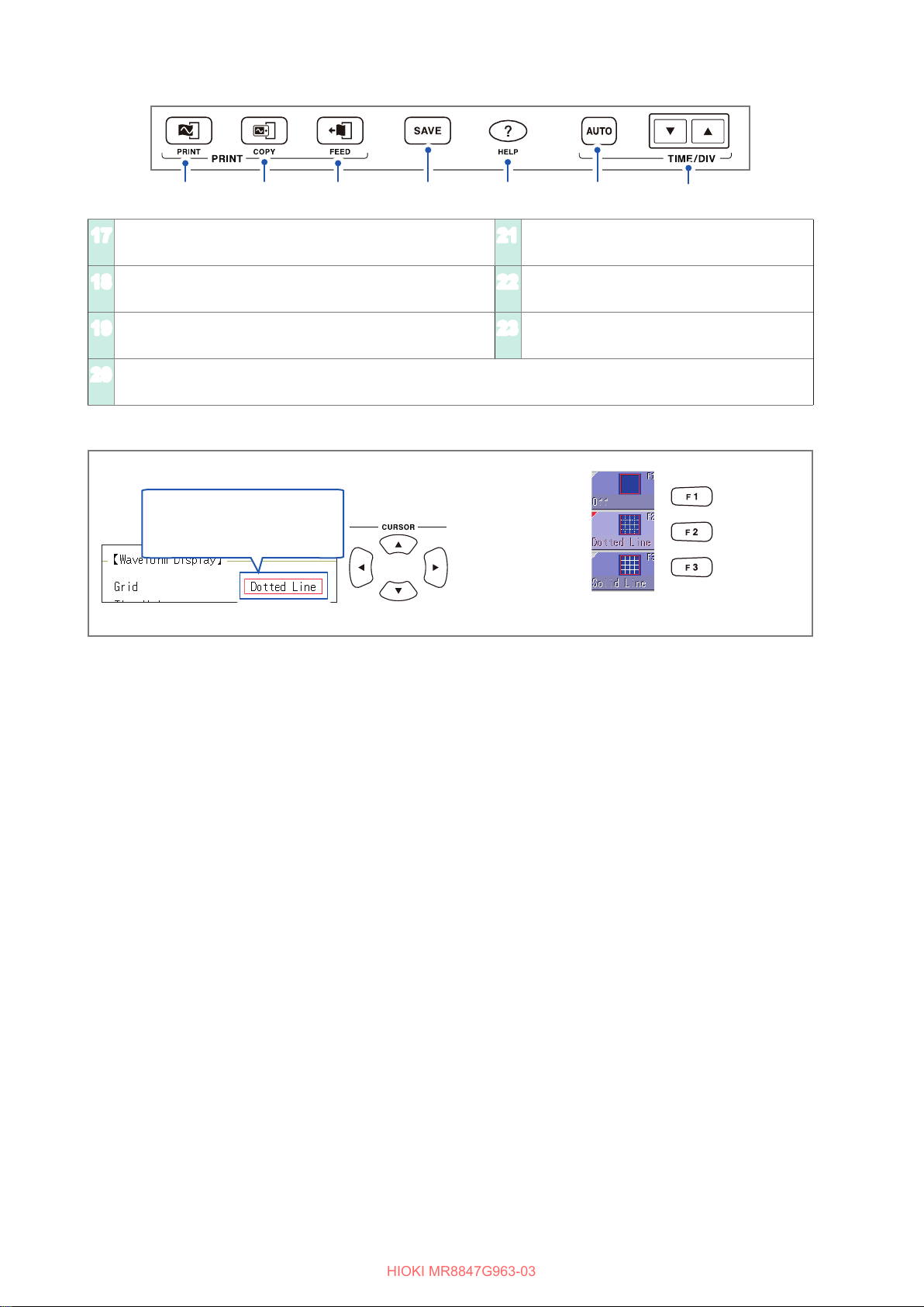
Screen structure and operation
overview
The screen structure and overview of the operation keys of
the instrument
(p. 2)
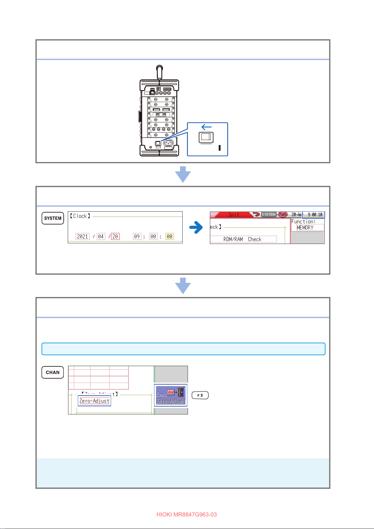
Preparations for Measurement The things to be done before carrying out measurement (p. 5)
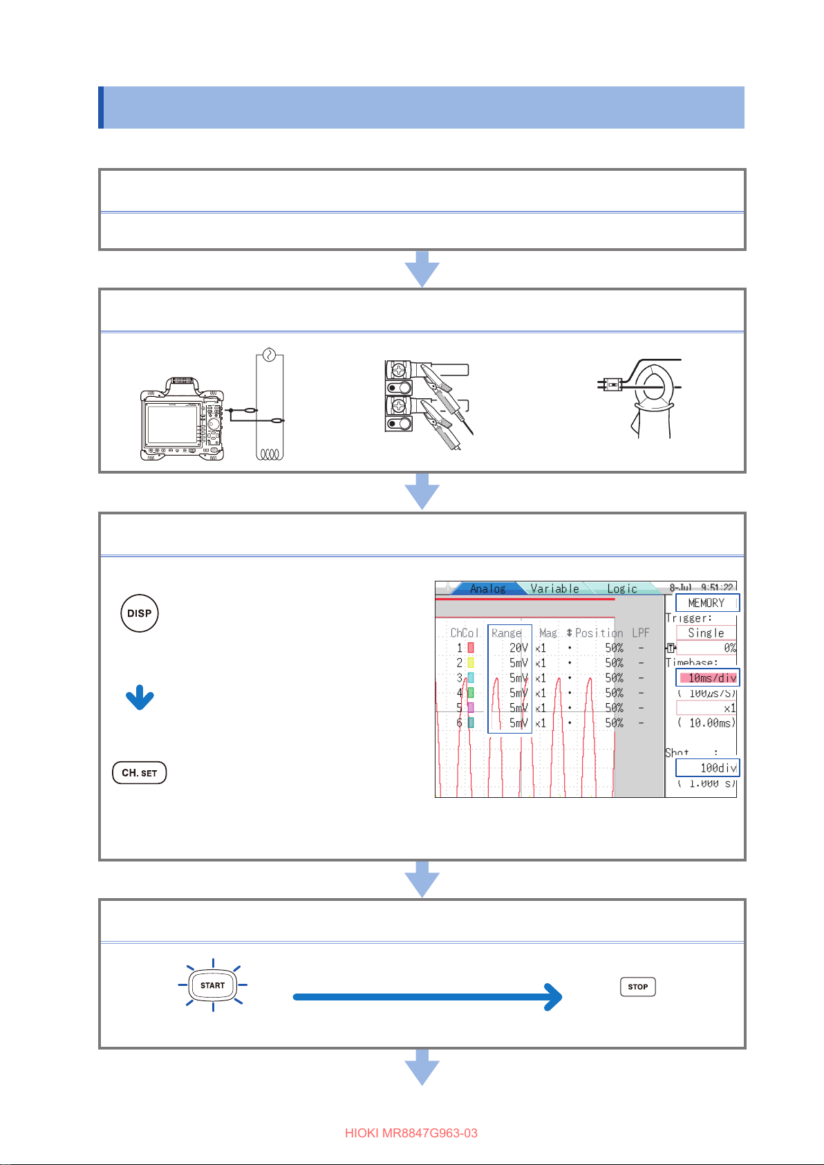
Measurement Procedure The procedure from pre-measurement check to analysis,
saving, and printing.
(p. 7)
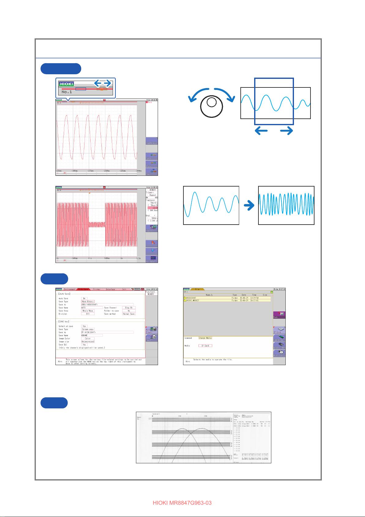
Measure the commercial power
supply
How to record waveforms of a 200-V commercial power
supply
How to save the data.
(p. 9)
Monitor abnormal occurrences How to record a voltage drop including power failure as an
example of special occurrences
How to record only abnormal occurrences, constantly
monitoring waveforms using the trigger function
How to save the data automatically
(p. 12)
Analyze the data How to observe waveform measured values and calculate
them using the A and B cursors
How to prevent the measured waveforms displayed on the
screen from being overlapped
(p. 14)
Print the data The printing method. (p. 21)
Convenient functions The auto-range function, pre-trigger, probe compensation (p. 24)
Others The screen, time axis and sampling, record length setting,
voltage axis and resolution, le transfer speed
(p. 27)
MR8847G963-03
10
9
8
7
6
5
4
3
2
1
Appx. Ind.