Flash Technology VANGUARD FTS 370i-2 User manual

Flash Technology, 332 Nichol Mill Lane, Franklin, TN 37067
www.flashtechnology.com
(615) 261-2000
VANGUARD®
FTS 370i-2 IR LED Integrated Beacon
Red LED Obstruction Lighting System
Reference Manual
Part Number F7913703
SERIAL NUMBER

ii Revision A – 05/17/2019 FTS 370i-2 IR
This page intentionally left blank.

FTS 370i-2 IR Revision A – 05/17/2019 iii
Front Matter
Abstract
This manual contains information and instructions for installing, operating and maintaining the
FTS 370i-2 IR LED Integrated Beacons.
Copyright
Copyright © 2019, Flash Technology®, Franklin, TN, 37067, U.S.A.
All rights reserved. Reproduction or use of any portion of this manual is prohibited without
express written permission from Flash Technology and/or its licenser.
Trademark Acknowledgements
Flash Technology®and Vanguard®are registered trademark names.
All trademarks and product names mentioned are properties of their respective companies and are
recognized and acknowledged as such by Flash Technology.
Applicable Specifications
The FTS 370i-2 IR beacon meets or exceeds requirements for an FAA Type L-864 beacon.
Additionally, the FTS 370i-2 IR beacon meets or exceeds requirements for an ICAO Annex 14,
Volume 1, 8th Edition Low Intensity Type B Obstacle Light.
Disclaimer
While every effort has been made to ensure that the information in this manual is complete,
accurate and up-to-date, Flash Technology assumes no liability for damages resulting from any
errors or omissions in this manual, or from the use of the information contained herein. Flash
Technology reserves the right to revise this manual without obligation to notify any person or
organization of the revision.
In no event will Flash Technology be liable for direct, indirect, special, incidental, or
consequential damages arising out of the use of or the inability to use this manual.
Warranty
Flash Technology warrants all components, under normal operating conditions, for 5 years.
Parts Replacement
The use of parts or components, in this equipment, not manufactured or supplied by Flash
Technology voids the warranty and invalidates the third party testing laboratory certification
which ensures compliance with FAA Advisory Circulars 150/5345-43J, 150/5345-53D, and
Engineering Brief No. 67D. The certification is valid as long as the system is maintained in
accordance with FAA guidelines (FR doc. 04-13718 filed 6-16-04).

iv Revision A – 05/17/2019 FTS 370i-2 IR
Personnel Hazard Warning
Dangerous Voltages
Dangerous line voltages reside in certain locations in this equipment. Also, this equipment may
generate dangerous voltages. Although Flash Technology has incorporated every practical safety
precaution, exercise extreme caution at all times when you expose circuits and components, and
when you operate, maintain, or service this equipment.
Avoid Touching Live Circuits
Avoid touching any component or any part of the circuitry while the equipment is operating. Do
not change components or make adjustments inside the equipment with power on.
Do Not Depend on Interlocks
Never depend on interlocks alone to remove unsafe voltages. Always check circuits with a
voltmeter after turning the circuit breakers off. Under no circumstances remove or alter the
wiring or interlock switches.

FTS 370i-2 IR Revision A – 05/17/2019 v
Table of Contents
This page intentionally left blank...................................................................................................... ii
Front Matter...................................................................................................................................... iii
Abstract......................................................................................................................................... iii
Copyright...................................................................................................................................... iii
Trademark Acknowledgements.................................................................................................... iii
Applicable Specifications............................................................................................................. iii
Disclaimer..................................................................................................................................... iii
Warranty....................................................................................................................................... iii
Parts Replacement ........................................................................................................................ iii
Personnel Hazard Warning................................................................................................................iv
Dangerous Voltages.......................................................................................................................iv
Avoid Touching Live Circuits.......................................................................................................iv
Do Not Depend on Interlocks........................................................................................................iv
List of Figures....................................................................................................................................vi
List of Tables.....................................................................................................................................vi
Section 1 - Overview..........................................................................................................................1
1.1 Specifications............................................................................................................................1
1.1.1 Regulatory Compliance and Certifications........................................................................2
1.2 Beacon Component Identification............................................................................................3
Section 2 – Installation – Mounting, Wiring, and Checkout..............................................................6
2.1 Mounting the Beacon................................................................................................................6
2.2 Wiring the Beacon....................................................................................................................8
2.3 Verifying Operation..................................................................................................................9
2.3.1 Power up............................................................................................................................9
2.3.2 Synchronization.................................................................................................................9
Section 3 - Operation........................................................................................................................10
3.1 Status Indicator LEDs.............................................................................................................10
3.2 Configuration Jumpers............................................................................................................11
Section 4 - Beacon Operation...........................................................................................................12
4.1 System Overview....................................................................................................................12
Section 5 - Maintenance and Troubleshooting.................................................................................15
5.1 Maintenance............................................................................................................................15
5.2 Troubleshooting......................................................................................................................15
5.3 Beacon Repair Procedures......................................................................................................16
5.3.1 Replace the Controller Core PCB....................................................................................16
5.3.2 Replace the Power Supply...............................................................................................17
5.3.3 Replace the GPS Antenna and Cable...............................................................................17
5.3.4 Replace the Surge Suppressors........................................................................................18
5.3.5 Replace the LED Engine Assembly ................................................................................18
5.4 Customer Service....................................................................................................................21
5.5 Ordering Parts.........................................................................................................................21
RMA POLICY..................................................................................................................................22

vi Revision A – 05/17/2019 FTS 370i-2 IR
List of Figures
Figure 1-1 – Beacon - External View...............................................................................................3
Figure 1-2 – Beacon Base Assembly................................................................................................4
Figure 1-3 – Beacon & Controller Assembly...................................................................................5
Figure 2-1 – Flashhead Dimensions & Mounting Outline ...............................................................7
Figure 3-1 – Status Indicator LEDs................................................................................................10
Figure 3-2 – Configuration Jumpers...............................................................................................11
Figure 4-1 – Beacon Wiring Diagram (Standard) ..........................................................................13
Figure 4-2 – Beacon Wiring Diagram (10 Conductor Option).......................................................14
Figure 5-1 – Beacon Component Locations...................................................................................19
Figure 5-2 – Base Component Locations .......................................................................................20
List of Tables
Table 2-1 – Standard Power & Alarm Connections...........................................................................8
Table 2-2 – Power, Alarm & Radar Interface Connections................................................................8
Table 3-1 – Status Indicator LEDs ...................................................................................................10
Table 3-2 – Configuration Jumpers..................................................................................................11
Table 5-1 – Troubleshooting - Beacon is in alarm ...........................................................................15
Table 5-2 – Troubleshooting - Beacon does not flash at night.........................................................15
Table 5-3 – Troubleshooting - Beacon flashes but not in sync ........................................................16
Table 5-4 – Troubleshooting - Beacon flashes in daytime...............................................................16
Table 5-5 – Optional Parts................................................................................................................21
Table 5-6 – Spare/Replacement Parts...............................................................................................21

FTS 370i-2 IR Revision A – 05/17/2019 1
Section 1 - Overview
The FTS 370i-2 IR (Infrared) LED Integrated FAA L-864 Flashing Red Beacon with Radar
Compatible Interface as shown in Figure 1-1, (hereafter referred to as the beacon) is pre-wired
with a power & alarm cable and operates from 120-240VAC 50/60 Hz. The only required
customer connection is the AC line; as the beacon incorporates an integrated controller which
flashes the beacon at night. The unit is equipped with an alarm contact and auxiliary control
input for connection to a radar system interface. The fail-safe design of the interface allows for
operation of the beacon if the radar system control wiring is interrupted. Also incorporated into
the controller is a GPS receiver and antenna, which allows synchronization to other beacons with
no additional wiring. The beacon consists of 24 high-performance LEDs that provide the FAA
required light output while consuming 99% less electrical power than an incandescent fixture.
The beacon incorporates 6 infrared LEDs. The addition of IR ensures visibility of the
obstruction to pilots aided by night vision goggles (NVG). The combination of standard Red
(620nm) LEDs and IR (850nm) LEDs ensures maximum visibility to pilots in all circumstances.
The FTS 370i-2 IR beacon also provide ICAO Medium-intensity, Type B Obstacle Light (Red)
compliance.
The beacon is designed for the lighting of wind turbines, towers, flare stacks, chimneys, offshore
oil platforms, petrochemical facilities and other obstructions to aerial navigation, as specified by
the FAA, FCC, ICAO and Transport Canada.
This manual provides guidance and recommendations for the installation, inspection, and testing
of the beacon assembly. Please read this document in its entirety before installing the beacon.
1.1 Specifications
Type FTS 370i-2: FAA L-864 Red Obstruction Light
FTS 370i-2: ICAO Medium-intensity, Type B Obstacle Light
Flash Rate 20/30/40 flashes per minute (FPM) (User Configurable)
Intensity 2,000 ± 25% ECD
AC Voltage 120 – 240V AC 50/60 Hz
Night Power Consumption
Flash rate (200ms flash duration)
20 FPM 30 FPM 40 FPM
FTS 370i-2 IR * 7 Watts 10 Watts 13 Watts
Operating Temperature -40°F to +131°F (-40°C to +55°C)
Aux Input Control Voltage 5 – 30 Volts AC/DC
Height / Width 8.69” x 15.75” (220.7mm x 400 mm)
Bolt Hold Down Standard 13.25” (336.5 mm)
Weight 26.3 lbs. (11.93 kg); With 50ft cable: 32.3 lbs. (14.7 kg)
* Power Consumption is 2 Watts in standby.

2 Revision A – 05/17/2019 FTS 370i-2 IR
1.1.1 Regulatory Compliance and Certifications
•ETL Certified to Federal Aviation Administration (FAA): AC No. (150/5345-43J). FAA
Engineering Brief No. 67D
•Compliant to Canadian Aviation Regulations (CAR’s): Standard 621
•Compliant to International Civil Aviation Organization (ICAO), Aerodromes, Annex 14,
Volume 1, Eighth Edition, dated July 2018

FTS 370i-2 IR Revision A – 05/17/2019 3
1.2 Beacon Component Identification
Figure 1-1 – Beacon - External View
GPS Antenna
Light Collector
(Photodiode)
Fresnel Lens
&
LED Engine
Assembly
Ground Lug
Base Assembly

4 Revision A – 05/17/2019 FTS 370i-2 IR
Figure 1-2 – Beacon Base Assembly
Power
Supply
Surge
Suppressors
TB1

FTS 370i-2 IR Revision A – 05/17/2019 5
Note: FTS 370i-2 shown.
Figure 1-3 – Beacon & Controller Assembly
Mother
Board
GPS Antenna
Connection
Harness
Connector
LED Engine with
Core Access Cover
& Harness Installed
Status LED
Indicators
Configuration
Jumpers
Controller
Core PCB

6 Revision A – 05/17/2019 FTS 370i-2 IR
Section 2 – Installation – Mounting, Wiring, and Checkout
Warning
Read the warning on page ix now. Remove power from all wiring and circuitry before installing
or performing work on the beacon. It is the responsibility of the installer to comply with all
applicable electrical codes.
Important!
For proper operation and optimal protection from Lightning and EMI, ensure that the
base is electrically bonded to the site grounding system using 8 AWG wire minimum
connected to the supplied external ground lug.
Flash Technology recommends the installation of one or more lightning rods near the
beacon. The copper lightning rod(s) should be located approximately 18 inches away from
and extend a minimum of three feet above the height of the beacon.
Installation Procedure:
1. Mount the beacon (Section 2.1)
2. Wire the beacon power (Section 2.2)
3. Verify operation (Section 2.3)
4. Wire the beacon monitoring connections (Section 2.2)
5. Confirm monitoring status by disconnecting power to the beacon. This should create an alarm.
After all steps are completed successfully, the installation is complete.
2.1 Mounting the Beacon
Flash Technology recommends the installation of one or more lightning rods near the beacon.
The copper lightning rod(s) should be located approximately 18 inches away from and extend a
minimum of three feet above the height of the beacon.
The beacon should be positioned so that the light collector for the photodiode has an
unobstructed view of the polar sky. Also, it must not view direct or reflected artificial light. The
GPS antenna located on top of the beacon must have an unobstructed view of the sky for proper
reception and synchronization.
The beacon is mounted to the tower pedestal or optional mounting bracket1utilizing supplied
hardware. Four mounting holes are provided on the beacon base (Figure 2-1). These mounting
holes will align with most tower pedestals. The beacon should be installed level to maintain light
output in accordance with FAA/ICAO requirements.
1. An optional mounting bracket is available to accommodate various installation configurations
and to facilitate leveling the beacon. See Section 5.5 for ordering information.
FTS 370i-2 IR Revision A – 05/17/2019 7
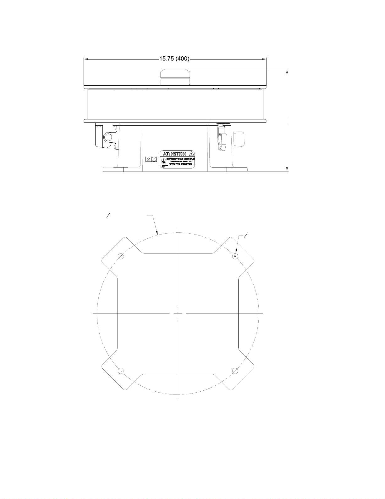
Note: All dimensions are in inches (millimeters).
Figure 2-1 – Flashhead Dimensions & Mounting Outline
13.25 (336.5)
0.63 (16) THRU
O
(TYP OF 4)
8.69 (220.7)
O

8 Revision A – 05/17/2019 FTS 370i-2 IR
2.2 Wiring the Beacon
The beacon is supplied with a 50-foot length of power & alarm cable pre-wired to the internal
electronics to facilitate installation (see Table 2-1). The only connections required are power
(120-240 VAC, 50/60 Hz) and ground. The ground wire must be connected for proper operation
and protection of the beacon.
Optional dry contact monitoring connections permit monitoring of beacon operation. The
contact is closed when the beacon is operating normally and no fault is detected.
The Auxiliary Control Input allows an external device, such as a radar system, to inhibit the
flashing of the beacon (see Table 2-2). The acceptable input voltage range for the Control Input
is 5 – 30 Volts AC/DC. The optional 10 conductor cable is required to utilize this feature.
Table 2-1 – Standard Power & Alarm Connections
5 Conductor Cable
Wire
Color Function FTB 370i-2 Beacon
Internal Connections External
Connections
Black Input Power TB1 - L1 (120 VAC) - Line
(240 VAC) - L1
White Input Power TB1 - L2 (120 VAC) - Neutral
(240 VAC) – L2
Green Ground TB1 - GND Ground
Red Alarm Contact TB1 - COM Alarm Input
1
Orange Alarm Contact TB1- NC Alarm Input
1
Table 2-2 – Power, Alarm & Radar Interface Connections
10 Conductor Cable (Optional)
Wire
Color Function FTB 370i-2 Beacon
Internal Connections External
Connections
Black Input Power TB1 - L1 (120 VAC) - Line
(240 VAC) - L1
White Input Power TB1 - L2 (120 VAC) - Neutral
(240 VAC) – L2
Green Ground TB1 - GND Ground
Red Alarm Contact TB1 - COM Alarm Input
1
Orange Alarm Contact TB1- NC Alarm Input
1
Brown Auxiliary Control Input TB1 – AUX - Control Output
2
Blue Auxiliary Control Input TB1 - AUX + Control Output
2
Violet Ground Chassis GND Ground
Yellow Ground Chassis GND Ground
Gray Ground Chassis GND Ground
Drain Ground Chassis GND Ground
1. Refer to the monitoring system manufacturer’s installation manual for connection locations.
2. Refer to the radar system manufacturer’s installation manual for connection locations.

FTS 370i-2 IR Revision A – 05/17/2019 9
2.3 Verifying Operation
Apply power to the beacon and verify operation as indicated by the beacon and Status Indicator
LEDs.
Note: See Section 3.1 for a description each Status Indicator LED,
2.3.1 Power up
When powered up, all indicator LEDs are turned on for 10 seconds providing easy verification of
operation. The beacon will begin flashing and will turn off after 40 seconds if the photodiode
detects sufficient light. Otherwise, the beacon will remain on until the ambient light rises to a
sufficient level.
2.3.2 Synchronization
For synchronization to occur, the GPS antenna (located on top of the beacon) must have an
unobstructed view of the sky. As much as 15 minutes may be required for the beacon to achieve
a GPS signal lock. Following power up, the Sync Alarm and Sync Status LEDs will turn off.
Once a GPS signal lock is achieved, the Sync Status LED will turn on. This is the normal
operating condition.
Note: After one hour of operation, the Sync Alarm will turn on if a GPS signal lock has not been
achieved. The alarm will turn off once a GPS signal is locked. Refer to Section 5 if the Sync Alarm
remains on for more than 15 minutes.

10 Revision A – 05/17/2019 FTS 370i-2 IR
Section 3 - Operation
3.1 Status Indicator LEDs
Status indicator LEDs are located on the Controller Core PCB inside the beacon. A description
of each is provided below. See Section 2.3 for additional information regarding the Status
Indicator LEDs.
Figure 3-1 – Status Indicator LEDs
Table 3-1 – Status Indicator LEDs
LED Description Function
D9 Power Input power is present.
D2 Sync Status Off during power up. Turns on after a GPS signal lock is achieved. Off
when Sync alarm is present.
D3 Mode Status Blinks in synchronization with the beacon flash.
D4 Red LED Alarm Output from the beacon is below the minimum regulatory allowance.
D21 IR LED Alarm Output from the IR LEDs has diminished by more than 25% of nominal.
D5 PD Alarm More than 19 hours have passed since the unit transitioned modes via
the photodiode.
D6 Sync Alarm More than one hour has passed since the unit received a GPS Sync
signal or an antenna fault is present.
D7 Ant. Open The GPS antenna is disconnected or has failed.
Sync Alarm will accompany the Ant. Open alarm.
D8 Ant. Short The GPS antenna is shorted.
Sync Alarm will accompany the Ant. Short alarm.

FTS 370i-2 IR Revision A – 05/17/2019 11
3.2 Configuration Jumpers
Configuration jumpers are located on the Controller Core PCB inside the beacon. A description
of each is provided below. To configure a particular option, move the spare jumper shunt to the
specified location.
Figure 3-2 – Configuration Jumpers
Table 3-2 – Configuration Jumpers
1. To activate mode override, the jumper must be installed while power is applied to the beacon.
The jumper has no effect if it is installed when the beacon is powered down.
2. Default flash rate is twenty (20) flashes per minute with no jumper installed on JP6 or JP7.
Jumper Description Function
JP11MAN. NIGHT Forces the beacon into Manual Night mode for 30 minutes.
JP21MAN. DAY Forces the beacon into Manual Day mode for 30 minutes.
JP3 ----- Spare Jumper
JP4 LEGACY Unit operates at ½ duty cycle.
JP5 PD DEFEAT The PD Alarm is disabled when the PD Defeat jumper is installed.
JP6230 FPM Thirty (30) flashes per minute.
JP7240 FPM Forty (40) flashes per minute.
JP8 SYNC1 (Lighting Equipment by others) Closed: Orga Sync (Open SYNC 2)
JP9 SYNC2 (Lighting Equipment by others) Closed: Unimar Sync (Open SYNC 1)
JP10 ALARM (Jumper Installed) Reduces LED output below minimum regulatory
specification to test the system alarm circuitry.

12 Revision A – 05/17/2019 FTS 370i-2 IR
Section 4 - Beacon Operation
4.1 System Overview
The beacon wiring diagrams are shown in Figures 4-1 and 4-2. The standard five conductor
power & alarm cable, shown in figure 4-1, provides connection of the AC line (3 wires) and
alarm monitoring connections (2 wires). The optional ten-conductor cable, shown in Figure 4-2,
provides the same connections and adds connections for the auxiliary control input (2 wires).
The remaining 3 conductors and drain wire are connected to chassis ground.
The AC line may be 120-240VAC 50/60Hz. The dry contact alarm connections are closed when
the beacon is operating normally and no fault is detected. The voltage range for auxiliary control
input is 5 – 30 Volts AC/DC. The beacon flash will be inhibited when voltage within the
specified range is applied to the terminals labeled AUX + and AUX -.
The Controller Core PCB (370i-2 IR 2423800) senses ambient light focused by the light
collector onto the photodiodes and at night flashes the LED beacon. A GPS antenna and
integrated receiver permit synchronization to other beacons. The Controller Core PCB detects
alarm conditions including beacon failure, photodiode alarm, and synchronization fault. A clear
polycarbonate cover provides access to view the status and alarm LEDs to permit easy
determination of proper operation and fault diagnosis.
The LED Engine assembly contains high-performance LEDs, which illuminate when powered by
the Controller Core PCB. The complete assembly (370i-2 IR 1370480) is easily replaced when
field service is required.
The Power Supply (5150501) and the Surge Suppressors (11000016050) are located in the base
of the beacon. The power supply generates the proper DC current to the Controller Core PCB
when AC line voltage is applied at its input. The surge suppressors, wired in line with and
directly across the AC Line, provide protection from incoming lightning and transient voltage
induced surges.

FTS 370i-2 IR Revision A – 05/17/2019 13
Figure 4-1 – Beacon Wiring Diagram (Standard)

14 Revision A – 05/17/2019 FTS 370i-2 IR
Figure 4-2 – Beacon Wiring Diagram (10 Conductor Option)
Table of contents
Other Flash Technology Lighting Equipment manuals

Flash Technology
Flash Technology VANGUARD FTS 270 User manual

Flash Technology
Flash Technology Vanguard Red FTS 371 User manual

Flash Technology
Flash Technology VANGUARD FTS 370d User manual

Flash Technology
Flash Technology FTB 312-3 User manual

Flash Technology
Flash Technology Vanguard FTS 370 User manual

Flash Technology
Flash Technology R247-G User manual

Flash Technology
Flash Technology FTS 812 L User manual

Flash Technology
Flash Technology FTS 350i-2 User manual

Flash Technology
Flash Technology VANGUARD FTS 370d User manual

Flash Technology
Flash Technology Vanguard Red FTS 371 SMART User manual


