Avlite AV-OL-KT-A1 Supplement

V1.0
INSTALLATION & SERVICE MANUAL
AV-OL-KT-A1
Obstruction Lighting Kit
FAA - A-1

2
Version No. Description Date Reviewed Approved Design
1.0 AV-OL-KT-A1 Manual Launch September 2019 P. Naidu W. Evans M. Sugars

AV-OL-KT-A1 - Obstruction Light Kit
Installation & Service Manual
Latest products and information available at www.avlite.com 3
Table of Contents
1.0 Introduction ...............................................................................................................4
2.0 Technology.................................................................................................................5
3.0 AV-OL-KT-A1 Models................................................................................................6
3.1 Available Options....................................................................................................................................... 9
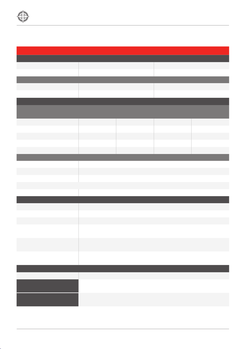
4.0 AV-OL-KT-A1 Data Sheet....................................................................................... 10
5.0 Safety Information...................................................................................................11
6.0 Operation and Setup.............................................................................................. 12
6.1 System Overview......................................................................................................................................12
6.1.1 GPS Synchronisation.....................................................................................................................12
6.1.2 L-864......................................................................................................................................................13
6.1.3 L-810(F).................................................................................................................................................15
6.1.4 T2 Controller......................................................................................................................................16
6.1.5 Interface Wiring...............................................................................................................................17
7.0 Unpacking, Installation, Wiring and Setup ......................................................... 18
7.1 Unpacking ......................................................................................................................................................18
7.2 Installation......................................................................................................................................................18
7.2.1 Tools Required ..................................................................................................................................19
7.2.2 Additional Tools Required........................................................................................................ 20
7.2.3 Cabling Requirements............................................................................................................... 20
7.2.4 Factory Settings............................................................................................................................ 20
7.2.5 Installation Recommendation............................................................................................... 20
7.3 Testing Procedure...................................................................................................................................37
8.0 Maintenance and Servicing ................................................................................. 38
9.0 Replacement Parts ................................................................................................ 38
10.0 Troubleshooting..................................................................................................... 39

4
1.0 Introduction
Congratulations! By choosing to purchase an Avlite product, you have become the owner
of one of the most advanced obstruction products in the world.
Avlite Systems draws on more than 25 years of experience in the design and manufacture
of navigation aids, and particular care has been taken to ensure your light gives years of
trouble-free service.
As a commitment to producing the highest quality products for our customers, Avlite has
been independently certified as complying with the requirements of ISO 9001:2015 quality
management system.
By taking a few moments to browse through this booklet, you will become familiar with the
versatility of your lighting kit, and be able to maximise its operating function.
Please remember to complete the Avlite warranty registration card accompanying your
light.
Acronyms and Abbreviations
The following abbreviations will be used throughout this Installation Manual:
cd candela
ft. foot
in. inch
LED Light Emitting Diode
VAC Volts, Alternating Current
VDC Volts, Direct Current
AWG American Wire Gauge
CMI Combined Medium Intensity

AV-OL-KT-A1 - Obstruction Light Kit
Installation & Service Manual
Latest products and information available at www.avlite.com 5
2.0 Technology
Avlite Systems is a world-class solar lighting systems manufacturer with a proven
reputation for rapid, innovative, and agile technology solutions designed specifically
for defence, government, civil and humanitarian aid operations in the most remote,
toughest environments.
Electronics
Avlite employs leading in-house electronic engineers in the design and development of
software and related circuitry. All individual electronic components are sourced directly by
Avlite procurement staff ensuring that only the highest quality components are used in our
products.
LED Technology
All Avlite lights use the latest advancements in LED (Light Emitting Diode) technology as a
light source. The major advantage of LED’s over traditional light sources is well established
in that they typically have an operational life in excess of 100,000 hours, resulting in
substantial savings to maintenance and servicing costs.
Precision Construction
Commitment to investing in the design and construction of injection-moulded parts
including optic lenses, light bases and a range of other components ensures that all Avlite
products are of a consistent and superior quality.
Optical Performance
Avlite manufactures a range of aviation LED lenses moulded from multi-cavity dies. The
company has superior in-house lens manufacturing capabilities to support outstanding
optical performance.
Award-winning, Patented Technology
Several United States and Australian patent registrations are held on Avlite’s range of
innovative designs, with other regional patents pending in Canada, United Kingdom and
Europe.

6
3.0 AV-OL-KT-A1
The AV-OL-KT-A1 Obstruction Lighting Kit integrates Avlite’s world class LED fixtures with
an application specific control and monitoring system to provide a full turnkey solution for
A1 defined structures ranging between 150 and 350 feet (45-106 meters). These include
telecommunication towers and utility towers, wind turbines, cranes, buildings and other tall
structures.
The A-1 Obstruction Solution comes fully assembled, ready to install, and includes the
following items:
• 1 x L-864 Medium Intensity Obstruction Light
• 3 x L-810(F) Obstruction Lights
• All necessary Junction Boxes
• Central Control Unit
The top light (L-864) and middle lights (L-810(F)) are illuminated for night operation and are
designed to flash with GPS flash synchronisation.
The A-1 Obstruction Solution is available in two input power configurations, a universal AC
(90-264VAC) or 24-48 VDC (solar compatible) and comes with Star2M monitoring via GSM
or SATCOM as options.
The best in class system power draw allows tower owners to utilize solar for locations
lacking reliable and or cost-effective access to regular utility power. Avlite’s experience,
knowledge and tools for solar applications provides years of maintenance free, off-grid
operation with an emphasis on FAA compliance.
With a range of accessories including brackets, cable and junction boxes, utility and
telecommunication companies, electrical contractors and state and local governments can
now quickly and easily purchase all obstruction lighting components from a single source,
simplifying the ordering process and reducing the possibility of incompatible, stand-alone
components from different manufacturers.
Note: This installation and service manual must be used in conjunction with the installation
manuals of the individual components.

AV-OL-KT-A1 - Obstruction Light Kit
Installation & Service Manual
Latest products and information available at www.avlite.com 7
3 x L-810(F) - AV-OL-L810F
167 (6.57”)
137 (5.4”)
121 (4.75”)
119 (4.69”)
121 (4.75”)
119 (4.69”)
Standard Model Model shown with optional
1 inch pipe thread adapter
[4.75in]
121mm
[4.69in]
119mm
[5.4in]
137mm
PCD
7.874
200.00
6 Places
1 x L-864 Beacon - AV-OL-FL864
[9in]
230mm
[4in]
104mm
[6in]
151mm
Note: Mounting hardware not included.
1 x Control Unit
[23.6in]
600mm
[15.8in]
400mm
2
0.00 A3
SolidWorks
mm
Drawn in:-
Units
Sheet Size:-
naturalFinish:-
Assem1
Material <not specified> -
Wt(Kg) each:-
Material/Quantity
N/A
XXXXXX-XXX
N/A
General Tolerances
345
X.XX
X.X
X
±0.1
±0.3
±1.2
X.X
X
±0.5°
±1.0°
±0.5
±2.0
Angular
X.X Drawing Rev:-
Drawn:-
Approved:-
Checked:-
0
E1 Marketing Drawing
Qty per Ass'y:-
Drawing No:-
File Name:-
Sheet
Scale
Projection
Next Ass'y:-
1:10 1 of 1
Model Rev:-
Sealite
0
A
B
C
D
E
F
G
9876
Linear Radii
X
1
18.5in
470mm
24in
610mm
652mm
25.6in
20in
508mm
Notes:-
Break all sharp edges.1.
Use 3D Model for Machining.2.
Refer Drawing for GEO Tol and Dimension Tol.3.
Part Nº .4.
Zone Rev Model
Rev ECR No. Description Date:- Drawn:- Approved:-
261mm
10.3in
26.5in
673mm
[7.9in]
200mm
2
0.00 A3
SolidWorks
mm
Drawn in:-
Units
Sheet Size:-
naturalFinish:-
Assem1
Material <not specified> -
Wt(Kg) each:-
Material/Quantity
N/A
XXXXXX-XXX
N/A
General Tolerances
345
X.XX
X.X
X
±0.1
±0.3
±1.2
X.X
X
±0.5°
±1.0°
±0.5
±2.0
Angular
X.X Drawing Rev:-
Drawn:-
Approved:-
Checked:-
0
E1 Marketing Drawing
Qty per Ass'y:-
Drawing No:-
File Name:-
Sheet
Scale
Projection
Next Ass'y:-
1:10 1 of 1
Model Rev:-
Sealite
0
A
B
C
D
E
F
G
9876
Linear Radii
X
1
18.5in
470mm
24in
610mm
652mm
25.6in
20in
508mm
Notes:-
Break all sharp edges.1.
Use 3D Model for Machining.2.
Refer Drawing for GEO Tol and Dimension Tol.3.
Part Nº .4.
Zone Rev Model
Rev ECR No. Description Date:- Drawn:- Approved:-
261mm
10.3in
26.5in
673mm

8
Note: Mounting hardware not included.
1 x Top Level Junction Box
1.
Zone
Rev
Model
Rev
ECR No.
Description
Date:-
Drawn:-
Approved:-
A3
--
002210-001-000
General Tolerances
Linear
X
X.X
X.XX
±1.2
±0.3
±0.1
Angular
X
X.X
±1.0°
±0.5°
±2.0
±0.5
Radii
X
X.X
0
002210-001-000
1:2
Model Rev:-
Sealite
0
A
B
C
D
E
F
G
987654321
1.
Zone
Rev
Model
Rev
ECR No.
Description
Date:-
Drawn:-
Approved:-
A3
--
002210-001-000
General Tolerances
Linear
X
X.X
X.XX
±1.2
±0.3
±0.1
Angular
X
X.X
±1.0°
±0.5°
±2.0
±0.5
Radii
X
X.X
0
002210-001-000
1:2
Model Rev:-
Sealite
0
A
B
C
D
E
F
G
987654321
1.
2.
Zone
Rev
Model
Rev
ECR No.
Description
Date:-
Drawn:-
Approved:-
A3
--
002210-002-000
General Tolerances
Linear
X
X.X
X.XX
±1.2
±0.3
±0.1
Angular
X
X.X
±1.0°
±0.5°
±2.0
±0.5
Radii
X
X.X
0
002210-002-000
1:2
Model Rev:-
Sealite
0
A
B
C
D
E
F
G
987654321
1.
2.
Zone
Rev
Model
Rev
ECR No.
Description
Date:-
Drawn:-
Approved:-
A3
--
002210-002-000
General Tolerances
Linear
X
X.X
X.XX
±1.2
±0.3
±0.1
Angular
X
X.X
±1.0°
±0.5°
±2.0
±0.5
Radii
X
X.X
0
002210-002-000
1:2
Model Rev:-
Sealite
0
A
B
C
D
E
F
G
987654321
[7.74in]
197mm
[11.77in]
299mm
[8.68in]
221mm
[10.32in]
262mm
[4.78in]
121mm
[4.86in]
123mm
Note: Mounting hardware not included.
1 x Mid Level Junction Box

AV-OL-KT-A1 - Obstruction Light Kit
Installation & Service Manual
Latest products and information available at www.avlite.com 9
3.1 Available Options
• Solar Input Power (for 24VDC) – Call Avlite for details.
• Cable Kit (suitable for 350 ft. structure) Includes:
275’ of 18 AWG, 3 Conductor wire
275’ of 10 AWG, 2 Conductor wire
165’ of 18 AWG, 5 Conductor wire
• Light Mounting Brackets (each)
For L864 Right Angle Pole Mounting Bracket-Medium Intensity Fixtures
For L-810(F): Right Angle Mounting Bracket-Low Intensity Fixtures
• Remote Monitoring and Control
Avlite offers remote Star2M monitoring via GSM or SATCOM.
Operators can remotely monitor the status of their installation from a compatible
device. The system can also be configured to send out SMS text messages or
e-mail alerts to designated operators should alarm conditions be triggered, such
as low voltage or light failure.
Please contact Avlite for operational information for the Monitoring & Control
options. Visit https://www.star2m.com to find out more about Star2M
• Mounting Bolt Kit (includes bolts, nuts, washers)
Please contact Avlite for further details
• Control Unit Mounting Hardware
2” pipe clamps
¾” pipe clamps
Please contact Avlite for further details.

10
4.0 AV-OL-KT-A1 Data Sheet
FAA E1 Obstruction Kit AC DC
Electrical Characteristics
Input Voltage 90-264VAC 24-48VDC
Input Frequency 50/60 Hz N/A
Power Consumption
Peak 84VA 70W
Average Night: 6.6VA Night: 5.5W
Physical Characteristics
Dimensions Height
(inches/mm)
Width
(inches/mm)
Lens Diameter
(inches/mm)
Mass
(lbs./kg)
L-864 6 / 151 9 / 230 6.75 / 171 12.3 / 5.5
L-810(F) 5.4 / 137 4.75 / 121 3.875 / 100 0.375 / 0.4
Control Unit 23.9 / 600 15.8 / 400 7.9 / 200 63 / 28.5
Top Junction Box 4.86 / 123 8.68 / 221 7.74 / 197 7.05 / 3.2
Middle Junction Box 4.78 / 121 10.32 / 262 11.77 / 299 9.92 / 4.5
Mounting
L-864 200mm bolt pattern
AV-OL-L-810(F) ¾ inch pipe thread
Control Unit Wall mounted (mounting accessories available)
Top Junction Box Mounting accessories available
Middle Junction Box Mounting accessories available
Certifications and Compliance
CE EN61000-6-3:2007, EN61000-6-1:2007
Quality Assurance ISO9001:2015
Protection Rating Junction and Control Box: IP65/NEMA4X Lights: IP68
FAA L-810(F), L-864, Medium Intensity Obstruction Light, FAA AC 150/5345-
43H
Transport Canada CL-864 Canadian Aviation Regulations 2015-2, Standard 621 -
Obstruction Marking and Lighting, March 2016 Appendix B
DGAC L-864 Medium Intensity Obstruction Light, L-810(F) Low Intensity
Obstruction Light (Qualified by Intertek)
Intellectual Property
Trademarks AVLITE®is a registered trademark of Avlite Systems
Warranty * 5 year warranty on light fixtures
3 year warranty on Control Unit
Options Available • Cable Kit suitable for 350’ structures
• Mounting Brackets for L-864 and L-810(F)
*Please refer to the individual light installation manuals for further specifications

AV-OL-KT-A1 - Obstruction Light Kit
Installation & Service Manual
Latest products and information available at www.avlite.com 11
5.0 Safety Information
Before proceeding with installation or service, make sure the following conditions are met:
• Ensure the tower or mast is grounded (NO RF OR SHOCK HAZARD)
• Check the mast lighting circuit is not faulty
• Ensure power lines are not ‘live’ (NO ELECTRICAL HAZARD)
• Avoid touching live circuits!
• Avoid touching any component or any part of the circuitry while the unit is operating.
Do not change components or make adjustments inside the unit with power on.
• Make sure the light fixture mounting is vertically aligned to guarantee the required
beam pattern of the obstruction light.
• Make sure any nearby obstacles do not impede the lights’ beam pattern.
• When installing, comply with all local electrical code(s).
• Mains power should always be disconnected when work is being done in close
proximity to electrical fittings, and electrical work should only be done by a licensed
electrician.
• Operate the light only within the indicated electrical ratings and product usage
instructions.
• To ensure that the light and peripheral equipment function safely and correctly, use
cable in compliance with the effective local electrical code.
• Do not stare at the LED or shine the LED into your eyes or those of another person.
• Dispose of the product according to the local laws and regulations for your region, for
example, at a recycling centre that accepts electronic devices.

12
6.0 Operation and Setup
Avlite’s A1 Obstruction Lighting Solution Kit consists of five components: A Control Unit
which provides power, day & night control and (optional) remote monitoring, a single L-864
red Medium Intensity obstruction beacon, and three L-810(F) red obstruction lights.
Both the L-864 and L-810(F) incorporate internal diagnostic checking and an alarm contact
for remote monitoring. The alarm relay is energized in normal operation and is released if
there is an LED or power fault.
An External Photocell allows the lights to automatically switch between day and night
mode. In night mode, all lights flash in synchronization with one another via integrated
GPS synchronisation, per the guidelines in the FAA 7460-1L Advisory Circular for lighting
A1 structures. In day mode, all lights are not illuminated. The Photocell output can also be
overridden for system testing and maintenance via the Photocell Bypass Switch. (See
section 6.1.3 for more information).
The Control Unit automatically evaluates the A1 lights for operation and performance while
providing local and remote display of information and alarms; operators can conveniently
view the lights’ real time status from the web based Star2M™ portal.
6.1.1 L-864
External
6.1 System Overview
PCD
7.874
200.00
6 Places
Power
Positive (+VDC) Black
Negative (-VDC) White
Data
Ground Ref (GNDA) White
PC Input (IN1) Black
Alarm Common (COM) Red
Alarm Signal (NC) Green

AV-OL-KT-A1 - Obstruction Light Kit
Installation & Service Manual
Latest products and information available at www.avlite.com 13
Power
Positive (+VDC) Black
Negative (-VDC) White
Data
Ground Ref (GNDA) White
PC Input (IN1) Black
Alarm Common (COM) Red
Alarm Signal (NC) Green
Lantern Status
The L-864 is fitted with one red and one yellow status LED and provides the operator with
an indication of the lantern status.
The LEDs are located on the side of the lantern.
The red status LED is used to indicate the health of the lanterns’ power system. The yellow
status LED is used to indicate the operational status of the lantern. These indicator LED’s
can be viewed at the base of the lens.
PCD
7.874
200.00
6 Places
RED
Status LED Lantern Status Lantern Condition
Steady Flat Battery cut off is in
effect
OFF Battery voltage is less than 43.0V
Slow High Voltage ON Battery voltage is above 54.0V
Off Optimal Voltage ON Battery Voltage is between 50.0V
– 54.0V
1 Quick OK Voltage ON Battery Voltage is between 48.0V
– 50.0V
2 Quick Low Voltage ON Battery Voltage is between 47.0V
– 48.0V
3 Quick Poor Voltage ON Battery Voltage is between 43.0V
– 47.0V
4 Quick Flat Voltage ON Battery voltage is less than 43.0V
Once the Flat Battery cut-off condition is in effect, the lantern will not turn back on until it
sees day light and the battery voltage is above the “OK” threshold for at least one minute.

14
YELLOW
Status LED Lantern Status Lantern Condition
Off Standby OFF Lantern is in Standby Mode
Quick Flashing
0.15s on, 0.15s
off
Day To Night Transitioning
(Dusk Till Dawn Mode)
OFF Light is activating and will turn
on after detecting 30 seconds of
continuous darkness
2 Quick
Flashes
every 2s
Operational, Not
Synchronized
ON Lantern is in Normal operating
condition. It is not connected to
any GPS synchronization
1 Quick
Flashes
every 2s
Operational, Sync in
Progress
ON Lantern is ‘re-syncing’ with GPS.
The lantern re-syncs with the GPS
every 15 minutes
Slow Flashing
1.5s on, 1.5s off
Operational, Synchronized ON Normal operating condition.
Lantern is synchronized to GPS-
enabled lanterns
2 Quick
flashes
every 11s
Operational, Synchronized
as Slave
ON Lantern is a Hard Wire
Synchronization
Slave
If the lantern is not fitted with the GPS Synchronisation option, then the following conditions
are not possible: 1 Quick Flash, and Slow Flashing.
For more information regarding the L-864, please consult the relevant sections of the
corresponding service and installation manual.
6.1.2 L-810(F)
External
167 (6.57”)
137 (5.4”)
121 (4.75”)
119 (4.69”)
121 (4.75”)
119 (4.69”)
Standard Model Model shown with optional
1 inch pipe thread adapter
Power and Data
Positive (+VDC) Red
Negative (-VDC) Black
IN1 White
COM Orange
NO Green

AV-OL-KT-A1 - Obstruction Light Kit
Installation & Service Manual
Latest products and information available at www.avlite.com 15
LED Fault
In the event of a singular LED fault, either open circuit or closed circuit across the LED, the
light unit will turn off all LED’s and actuate the Fault Relay.
For more information regarding the L-810(F), please consult the relevant sections of
the corresponding service and installation manual.
6.1.3 T2 Controller
The T2 Control Unit is an essential component of the A1 Obstruction Lighting Kit as it
provides power, control and monitoring of the light fixtures in the system.
For safety and security, the control enclosure comes with a safety interlock which prevents
access to the controller while the system is powered on.
The Controller is available in two input power configurations; a universal AC or DC and
comes with remote monitoring via Star2M with either GSM or Satcom telemetry types as
options.
By default, the control unit comes with 2 dry contacts for external monitoring of both the
L-864 and L-810(F) light fixtures which receive the associated alarm in the event of a power
or LED fault. (Note: External dry contact monitoring is unavailable if remote monitoring via
GSM or Satcom has been enabled)
A Photocell Bypass Switch is provided with the Control Unit to override the Photocell output
for system testing and maintenance and is factory-set to AUTO (auto day/night) mode.
The Control Unit with the AC option has an interface switch on the door. The DC version
has a circuit breaker in the cabinet for switching the power ON and OFF.
To test the function of lights for night operation, the system must be operating in Day
mode. Toggle the switch to Override by turning the switch to the right. All lights should
illuminate. To return to the Auto mode, return the switch to the Auto position.
Note: Time delays are to be expected when changing modes. Allow up to 1 minute to
change between functions.

16
6.1.4 Interface Wiring
Top Junction
Box
P ow er c abl e: 2 x 1 0 A WG
Data cable: 4 x 18 AWG
T2 Controller
Data cable: 3 x 18 AWG
P ow er c abl e: 2 x 1 0 A WG
External
Photocell
P ower & Da ta cab le: 3 x 18 AW G
Middle
Junction Box
Power & Data cable:
5 x 18 AWG
Power & Data cable:
5 x 18 AWG
P ower & Da ta cab le :
5 x 18 AWG
L-810(F)
L-810(F) L-810(F)
L-864
Power & Data cable:
5 x 18 AWG

AV-OL-KT-A1 - Obstruction Light Kit
Installation & Service Manual
Latest products and information available at www.avlite.com 17
6.1.5 GPS Synchronisation
Avlite has utilized the latest advancements in GPS technology to develop an internal
synchronization system that is incorporated into the lights. Using overhead satellites,
multiple obstruction lights set to the same flash pattern will flash in unison. No additional
power supplies, aerials or control systems are required, and with its microprocessor-
based system, the GPS option is specifically designed to provide maximum reliability and
performance over a wide range of environmental conditions.
Operating Principle
Each light operates independently and requires no operator intervention. A minimum
of 4 satellites need to be in view for the built-in GPS receiver to collect time data. At
dusk, the light sensor will turn the light on. If time data is available, the light will come on
synchronized to every other light with the same selected flash code. Synchronisation is
achieved using an internal algorithm based on the highly accurate time base and time data
received from the satellites. The satellite data is provided from a number of earth stations
using atomic clocks as the time base. Continuous self-checking ensures that the light will
continue to run in synchronisation.
Light Activation
At power-up the microprocessor checks that the internal GPS module is programmed
correctly and is able to provide valid time base and time data. Once outside with a clear
view of the sky, valid data should become available within 20 minutes.
Note: Lights will not synchronise if different flash codes are selected.

18
7.0 Unpacking, Installation, Wiring and
Setup
7.1 Unpacking
Unpack all hardware and inspect for damage. If there is any damage, please contact your
Avlite Office.
Retain original packing material for possible future use in shipping.
7.2 Installation
WARNING:
Confirm that the power switch is toggled to the OFF position when
power is connected. DO NOT connect power to the PCU when the
control panel power switch is toggled to the PWR position. This may
result in damage to the power sources.
WARNING:
DO NOT connect directly to the DC output of a generator, or any
other unregulated power source. Connecting to an unregulated
source may result in damage.
WARNING:
Do not stare into light emitting diode (LED) beams.
CAUTION:
LED lights contain glass components. Do Not Drop.
Always follow the instructions outlined in the product manual when
cleaning the equipment. Improper cleaning methods and use of
unauthorized cleaning agents can damage equipment.

AV-OL-KT-A1 - Obstruction Light Kit
Installation & Service Manual
Latest products and information available at www.avlite.com 19
7.2.1 Tools Required
7.2.2 Location
Refer to FAA AC 150/5345-43 and FAA AC 70/7460-1L for site requirements for obstruction
lights.
Tools Needed (not supplied)
Flush Cutter
Tongue & Groove Pliers
Silicone Sealant
Cable Jacket Trimmer (optional)
Utility Knife
Electrical Tape
Insulated Terminal Crimper
Wire Strippers 10AWG to 18AWG Range
2.5mm Hex Key
2.0mm Flat Blade Precision Screwdriver
#2 Phillips Screwdriver
Junction Boxes (2) (owner supplied or optional
purchase)
Light Mounting Brackets (4) (optional purchase)
Cables (owner supplied or optional purchase)

20
7.2.3 Cabling Requirements
The installation of the AV-OL-KT-A1 Obstruction Lighting Kit requires the following cables (if
optional cable kit is not purchased):
7.2.4 Factory Configuration
• L-864 wired with 10ft flying leads (Power cable and Data cable).
• 1 x L-810(F) wired with 10ft flying lead.
• 2 x L-810(F) wired with 25ft flying lead.
• External Photocell wired with 25ft flying lead.
7.2.5 Installation Recommendation
Note: The sequence of steps can be adjusted for site requirements.
1. Wire and test the system on ground level.
Conduct a basic functional check to ensure that the lights turn on as expected. See section
7.3 Testing Procedure for more information.
Reference Point Cable
L-864 -Top Junction Box • Power Cable: 10 AWG 2 Conductor.
• Data Cable: 18 AWG 4 Conductor.
Top Junction Box - Control Unit • Power Cable: 10 AWG 2 Conductor.
• Data Cable: 18 AWG 3 Conductor.
L-810(F) - Middle Junction Box: • Power & Data Cable (x3) = 18 AWG 5 Conductor.
Middle Junction Box- Control Unit • Power & Data Cable = 18 AWG 5 Conductor.
Photocell - Control Unit: • Power & Data Cable = 18 AWG 3 Conductor.
This manual suits for next models
2
Table of contents
Other Avlite Lighting Equipment manuals

Avlite
Avlite AV-OL-MI Supplement

Avlite
Avlite AV-15 Supplement

Avlite
Avlite AV60 Supplement

Avlite
Avlite AV-OL-KT-I2 Supplement

Avlite
Avlite AV-09-4WL Supplement

Avlite
Avlite AV-426-L861 Supplement

Avlite
Avlite AV-70 Supplement

Avlite
Avlite AV-OL-FL864-12-R User manual

Avlite
Avlite AV-425-RF User manual

Avlite
Avlite AV-OL-ILAB-UM-R Supplement

Avlite
Avlite AV-OL-KT-I1 Supplement

Avlite
Avlite AV-OL-KT-I3 Supplement

Avlite
Avlite AV-OL-60 User manual

Avlite
Avlite AV23 Supplement

Avlite
Avlite AV-HLI2 Supplement

Avlite
Avlite AV-70 User manual

Avlite
Avlite AV-SAL-01 Supplement

Avlite
Avlite AV-BSBL User manual

Avlite
Avlite AV-OL-CMI Supplement

Avlite
Avlite AV-72-RF Supplement