Flintec CC1W-30klb User manual

Page 1 of 21 DOC No. 0095771
User’s
Manual
CC1W-30/50klb

User Manual - CC1W
Page 2 of 21 DOC No. 0095771
Table of Contents
1. Product description...........................................................................................3
2. Mounting instructions.......................................................................................4
2.1 Base Unit ..............................................................................................................................................4
2.2 Antenna Recommendations .................................................................................................................6
2.3 Remote Unit (Wireless Loadcell)..........................................................................................................9
2.4
Battery Installation
...............................................................................................................................10
3. Equipment Maintenance .................................................................................11
3.1
Battery Replacement
...........................................................................................................................11
4. Operation..........................................................................................................12
4.1
Base unit wireless channel selection (if needed)
........................................................................................13
5. Technical Specification...................................................................................14
6. Product Label...................................................................................................15
7. Product Dimensions........................................................................................16
8. Safety information ...........................................................................................18

User Manual - CC1W
Page 3 of 21 DOC No. 0095771
1. Product description
The CC1W is a wireless version of our CC1 pump off control load cell. The CC1W utilizes the same
proven design attributes as the CC1 - stainless steel, hermetic seal, fatigue rating and intrinsically safe
operation. The CC1W transmits polished rod load wirelessly which solves the industry wide problem
of cable failures. After months of development in the field, working hand in hand with end users, our
design addresses the most demanding concerns raised.
The CC1W technology sets our product apart from all wireless products currently available in the
market. The primary advantage we bring is extremely low power consumption. Despite the low
power consumption, the product can deliver a continuous flow of data, high signal strength and long
battery life. We also offer position sensing capability which is synchronized with the load
measurement. This eliminates the need for hall effect sensors or inclinometers and the costly
maintenance associated with each. The wireless enclosure also incorporates an independent
compartment for both the wireless technology and the battery. This allows for easy, single handed
access to the battery for replacement in the field. We carefully specified a pre-wired “D cell” battery
that is inexpensive and commercially available worldwide.
•Continuous flow of data: 100 readings per second
•Low power consumption: 12-18 month battery life
•High signal strength: +13dBm to +17dBm, 30-300 meter transmission
•HazLoc approved: UL rated for Class 1, Division 1 environments (see label for full approval)
•On-board position: +/-0.5% accuracy
•Security: Proprietary wireless transmission protocol
•Ease of use: independent battery access, commercially available battery
•Weatherproof: IP67 rating, rated for use in -70°F to 175°F (-55°C to 80°C)
Accessories:
Base/Receiver (included)
Antenna & Connection Cables (included)
Lithium Battery (Included)
Magnetic Mount or Post Mount for Base (user specified)
Load Spacer/Plate
Spherical Washer Set
User Manual - CC1W
Page 4 of 21 DOC No. 0095771
2. Mounting instructions
IMPORTANT
The employees responsible for the equipment installation and verification must take into
consideration all the actions concerning this subject specified in IEC 60079-14:2013 ed. 5.0
(Electrical installations design, selection and erection) standard. In addition to general
specifications associated with any system installed in hazardous locations, special attention
should be paid for specific requirements regarding intrinsic safety (section 12).
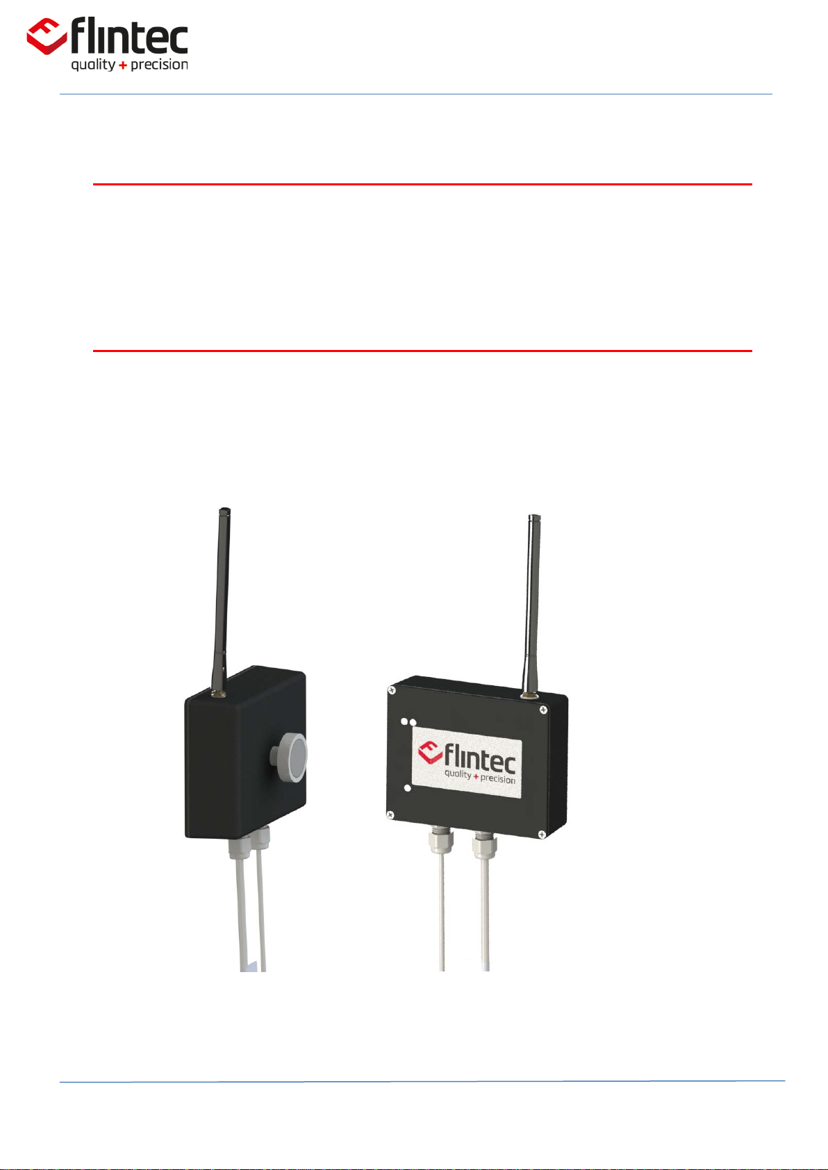
2.1 Base Unit
The “Base” (receiver) of the device comes with a magnet base for easy mounting on a metal
surface inside or outside of the pump controller cabinet. Base is mounting outside the hazardous
area and not intended to meet hazardous location safety standards.
Base Unit

User Manual - CC1W
Page 5 of 21 DOC No. 0095771
When the magnet base is not directly attached due to non-metallic surface or space
constraint, the base can be suitable fastened to any structure using brackets, plates or other
type of support.
_________________________________________________________________
IMPORTANT In order to achieve the best performance a vertical alignment of the antenna
must be ensured.
You may optionally use an extension cable to mount the antenna.
DIN rail mount
Pole mount with U-

User Manual - CC1W
Page 6 of 21 DOC No. 0095771
2.2 Antenna Recommendations
Omni Directional Antenna CC1W
base unit is equipped with an Omni-
directional antenna in order to provide
the widest possible signal coverage.
RP-SMA Connector (female)
The antenna is provided with a
threaded, weatherproof RP-SMA
female connector. This connector
must be properly tightened to the
male connector on the enclosure.
Vertical Alignment
In order to achieve the best
performance a vertical alignment
of the antenna must be ensured.
Line-of-sight
Is important to find, whenever
possible, a spot full line of sight
with the receptor where no
obstacles reside between the path.
Note: Fresnel Zone, the area around
the visual line-of-sight that radio
waves spread out into after they
leave the antenna must be clear or
the signal strength will be weakened
due to reflections.
Antenna Height
Taking advantage of the free
positioning of the base antenna,
a convenient place in height with
good clearance and away from
ground must be considered.
Note: The use of extension cables that
always represent attenuation and
signal strength losses should be
avoided if possible

User Manual - CC1W
Page 7 of 21 DOC No. 0095771
When mounting inside an enclosure
User Manual - CC1W
Page 8 of 21 DOC No. 0095771
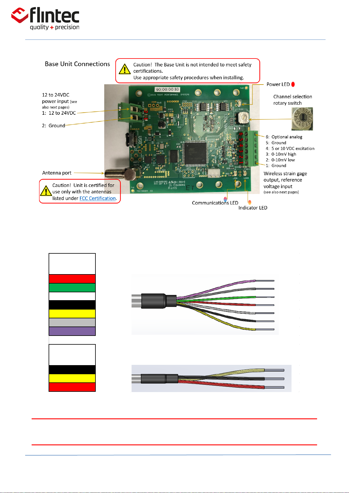
WARNING: Insulate unused leads to prevent shorting.
SIGNAL CABLE
COLOR CODE
RED Vref +
GREEN Sig +
WHITE Sig -
BLACK Vref -
YELLOW Shield
GRAY Sig 2 +
VIOLET Sig 2 -
POWER CABLE
COLOR CODE
BLACK Ground
YELLOW Shield
RED 12 to 24VDC

User Manual - CC1W
Page 9 of 21 DOC No. 0095771
2.3 Remote Unit (Wireless Loadcell)
CC1W must be mounted as same as any other regular loadcell on the polished rod.
_________________________________________________________________
IMPORTANT
Position the remote unit (Plastic enclosure with Flintec Logo) direct to the base unit for better
performance

User Manual - CC1W
Page 10 of 21 DOC No. 0095771
2.4 Battery Installation
CC1W remote unit powered by a primary battery and must be fitted suitably in the battery
compartment. The person in charge of the installation must verify that the battery not damaged or
soaked.
WARNING: This product is certified for use with TADIRAN TL-5930/F. Make sure the battery cable tuck
inside the compartment to prevent squeeze in between the edges when closing the door

User Manual - CC1W
Page 11 of 21 DOC No. 0095771
3. Equipment Maintenance
Safety and health standards in the workplace must be strictly observed for all personnel conducting
maintenance tasks.
This manual must be read and kept carefully, in order to be always at the operator's disposal in case of
need.
3.1 Battery Replacement
CC1W remote unit (transmitter) is powered from a specific battery
TADIRAN – TL-5930/F
The battery must be replaced in non-hazardous areas where no any potential of explosion
atmospheres.
1. Open up the battery compartment loosening the battery door knob (see section 2.4 on this manual).
2. Unplug the battery connector from housing.
3. Take the battery off.
4. Replace the battery for a new one.
5. Close the door and lock with the door knob (see section 3.3 on this manual)

User Manual - CC1W
Page 12 of 21 DOC No. 0095771
4. Operation
1. Disconnect or turn off power to the base unit.
2. Ensure the base antenna is connected.
The remote’s antenna is installed by the manufacturer; to preserve safety certifications, it
is not intended to be removed.
3. Ensure the manufacturer-supplied battery is connected to the remote unit.
4. The remote unit’s indicator LED, if viewable, will flash about twice per second.
5. Connect or turn on power to the base unit.
6. The base and remote will connect on the last-used radio channel in about a second.
7. If the base is set to use an alternate channel, it will switch the remote to that channel.
This only takes a few seconds.
8. Normal operation begins.
A reconstructed version of the 0-10mV or 0-20mV nominal load cell output will appear at
the base output.
9. As shown on section 4.1 on this manual, if radio interference occurs, an alternate channel
may be selected.
Caution! To preserve safety certifications, do not attempt to remove the remote
from its housing in order to view the LED.
User Manual - CC1W
Page 13 of 21 DOC No. 0095771
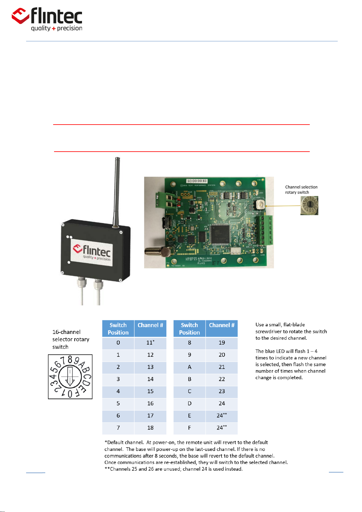
4.1
Base unit wireless channel selection (if needed)
Remove up the base top cover. The 4 Philips head screws attached to the flat base cover
loosened with the proper tool (manual Philips screwdriver).
WARNING: Gently lift the cover to prevent damaged to the 3 LED light tubes attached to the
cover.

User Manual - CC1W
Page 14 of 21 DOC No. 0095771
5. Technical Specification
Standard Specifications
lbf
30k, 50k
Rated Output
mV/V
2.00 ± 0.5%
mA (Optional)
4-20
Rated Position Output
% FS (Stroke)
± 0.5
Nonlinearity
% FS
± 0.25
Hysteresis
% FS
± 0.25
Non-Repeatability
% RO
± 0.1
Static Error Band
% FS Max
± 0.50
Temperature
Compensated Temperature Range
°F (°C)
-14 to 150 (-25 to 65)
Safe Operating Temperature Range
°F (°C)
-70 to 175 (-55 to 80)
Temperature Effect on Zero
% RO/°F Max
± 0.005
Temperature Effect on Output
%RO/°F Max
± 0.002
Zero Balance
% RO Max
± 1
Safe, Axial Load
% Capacity Max
200
Deflection at Capacity
inch Nom
0.005
Weight, Remote Unit
lb. nom
4.2
Fatigue Rating (Compression)
Min Cycles @Capacity
50,000,000
Shock Rating
g
Up to 500
Vibration Rating
MIL-STD-810G
514.6; 516.6
Sensor Element
17-4 PH Stainless Steel
Protection according EN60529
IP67 or higher
Electronics
Remote and Base Transceiver
Units Matched
Mac ID
(32bit) Specific; no external connection -
Paired unit
Data Rate
Readings/Sec
100
Radio Frequency
GHz
2.405 to 2.470
Radio Channels
Selectable (*)
14
Telemetry Range
Feet (Meters) (*)
100 - 1000 (30-300)
RF Power Output - Remote Unit
dBm (*)
Min = 13.0dBm, Max = 15.5dBm
RF Power Output - Base Unit
dBm (*)
Min = 16.0dBm, Max = 17dBm
Battery Life
Min @ 100 rps (**)
12 - 18 months
Battery Type
Remote Battery
(TL-5930/F) Lithium D Cell, 3.6VDC, 19Ah
Base Unit
Power Supply
VDC, mA
12 - 24; Min. 250mA
External Ref. (Virtual Excitation)
VDC
4.8-10.1
Virtual Bridge Resistance
Ω
700
(*) 2-3dBm; Telemetry range will change according to site RF Channel Settings
(**) Battery Life changes as per RF output; latency; Temp; antenna distances etc. Refer to Manufacturer for details.

User Manual - CC1W
Page 15 of 21 DOC No. 0095771
6. Product Label
Remote Unit (Transmitter)
Equipment Group II - All areas except Mines
Equipment Category and Environment 1 G - Gas, Vapor, Mist
Explosion Protection Ex - Conformity with some of the IECs protection modes
Protection Type ia - Intrinsic security “ia” protection mode
than mines. Gases Groups
Temperature Class T4 - Max surface temp 135°C (275°F)
Equipment Protection Level (EPL) Ga - Gas Atmospheres. Very high level of protection
Base Unit (Receiver)
Label
Label

User Manual - CC1W
Page 16 of 21 DOC No. 0095771
7. Product Dimensions
Remote Unit

User Manual - CC1W
Page 17 of 21 DOC No. 0095771
Base Unit (Receiver)
User Manual - CC1W
Page 18 of 21 DOC No. 0095771
8. Safety information
Intended Usage
A maximum temperature on the device enclosure must not reach temperatures higher than
80°C or lower than -55°C. This condition must be guaranteed permanently in order to be
compliant with the intrinsic safety certification. The CC1W radio device must not be placed
near heating or cooling sources that can put at risk.
As a radio node forming part of a wireless network its positioning can greatly affect its
coverage area and the strength of its signal. It is always recommend to position the
transceiver set free of obstructions and with good line-of-sight to the rest of the network and
whenever possible away of electrical noise sources that can cause interferences.
Lithium Batteries
When the CC1W equipment is powered by a Lithium battery (single), special care must be taken
in order to prevent damages. The battery is composed of a single Lithium-Thionyl Chloride (Li-
SOCl2) cell connected with an extension cable with a connector.
Do not apply pressure that may deform the battery
Do not use the battery if there are signs of swelling –
remove immediately
Do not directly heat or solder
Work areas should be free of sharp objects that could puncture the insulating material
IMPORTANT: The battery must be replaced in non-hazardous areas.
Maintenance Safety
There must be a competent person with enough skills and knowledge supervising all works
performed. Experienced and trained personnel must follow the industrial standard safety
protocol when authorized maintenance activities are carried out on the equipment.

User Manual - CC1W
Page 19 of 21 DOC No. 0095771
FCC Certification Statement
Note: This equipment has been tested and found to comply with the limits for a Class A digital
device, pursuant to part 15 of the FCC Rules. These limits are designed to provide reasonable
protection against harmful interference when the equipment is operated in a commercial
environment. This equipment generates, uses, and can radiate radio frequency energy and, if not
installed and used in accordance with the instruction manual, may cause harmful interference to
radio communications. Operation of this equipment in a residential area is likely to cause harmful
interference in which case the user will be required to correct the interference at his own expense.
Changes or modifications not expressly approved by the party responsible for compliance could
void the user's authority to operate the equipment.
This device complies with part 15 of the FCC Rules. Operation is subject to the following two
conditions: (1) This device may not cause harmful interference, and (2) this device must accept
any interference received, including interference that may cause undesired operation.
This device has been designed to operate with the antenna(s) listed below, having a maximum
gain of +3.2dBi. Antennas not included in this list or having a gain greater than +3.2dBi are strictly
prohibited for use with this device. The required antenna impedance is 50 ohms.
Base Unit
FCC ID: 2AUSA-CC1WRB
Permitted Antennas
Linx ANT-2.4-CW-HW, maximum gain of +3.2dBi
Linx ANT-2.4-CW-HW-T, maximum gain of +3.2dBi
Linx ANT-2.4-CW-HWR-RPS, maximum gain of +3.2dBi
Linx ANT-2.4-CW-RCS, maximum gain of -0.2dBi
Remote Unit
FCC ID: 2AUSA-CC1WRR
Permitted Antennas
Yageo ANTX100P112B24553, maximum gain of +2.2dBi
Molex 1461870150, maximum gain of +3.0dBi

User Manual - CC1W
Page 20 of 21 DOC No. 0095771
ISED RSS-Gen Notice
“This device complies with Industry Canada’s licence-exempt RSSs. Operation is subject to the
following two conditions:
(1) This device may not cause interference; and
(2) This device must accept any interference, including interference that may cause undesired
operation of the device.”
“Le présent appareil est conforme aux CNR d’Industrie Canada applicables aux appareils radio
exempts de licence. L’exploitation est autorisée aux deux conditions suivantes :
1) l’appareil ne doit pas produire de brouillage;
2) l’appareil doit accepter tout brouillage radioélectrique subi, même si le brouillage est susceptible
d’en compromettre le fonctionnement.”
ISED RSS-Gen Notice
“CAN ICES-3/NMB-1”
IC Certification Statement
This radio transmitter (identify the device by certification number, or model number if (Category II)
has been approved by Industry Canada to operate with the antenna types listed below with the
maximum permissible gain and required antenna impedance for each antenna type indicated.
Antenna types not included in this list, having a gain greater than the maximum gain indicated for
that type, are strictly prohibited for use with this device.
Le présent appareil est conforme aux CNR d'Industrie Canada applicables aux appareils radio exempts
de licence. L'exploitation est autorisée aux deux conditions suivantes : (1) l'appareil ne doit pas
produire de brouillage, et (2) l'appareil doit accepter tout brouillage radioélectrique subi, même si le
brouillage est susceptible d'en compromettre le fonctionnement.
Base Unit
IC: 25535-CC1WRB
Permitted Antennas
Linx ANT-2.4-CW-HW, maximum gain of +3.2dBi
Linx ANT-2.4-CW-HW-T, maximum gain of +3.2dBi
Linx ANT-2.4-CW-HWR-RPS, maximum gain of +3.2dBi
Linx ANT-2.4-CW-RCS, maximum gain of -0.2dBi
Remote Unit
IC: 25535-CC1BRR
Permitted Antennas
Yageo ANTX100P112B24553, maximum gain of +2.2dBi
Molex 1461870150, maximum gain of +3.0dBi
Other manuals for CC1W-30klb
1
This manual suits for next models
1
Table of contents
Other Flintec Control Unit manuals


