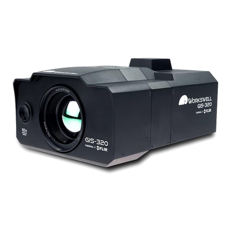
FLIR FlashSight User manual

Copyright © 2006, FLIR Systems, Inc. 431-0002-09-10
FlashSight™
User’s Guide
INDIGO OPERATIONS

FlashSight User’s Guide
431-0002-09-10
Version 100
FLIR Systems, Inc.
Indigo Operations
70 Castilian Dr.
Goleta, CA 93117-3027
Phone: 805.964.9797
Fax: 805.685.2711
www.indigosystems.com
EXPORT RESTRICTIONS
The information contained in this document may be controlled for export purposes by the United States
Government. Diversion contrary to US law is prohibited. Contact FLIR Systems, Inc., for more
information. This document and data disclosed herein or herewith is not to be reproduced, used, or
disclosed in whole or in part to anyone without the permission of FLIR Systems, Inc.
PROPRIETARY
The data in this publication shall not be disclosed without permission and shall not be duplicated, used, or
disclosed in whole or in part except to the extent provided in any contract of which this document is made
a part. This restriction does not limit the customer’s right to use information contained in this document if it
is obtainable from another source without restriction. The data subject to this restriction are contained in
all sheets of this document and related drawings and document specifications herein. FLIR reserves the
right to make changes to its products or specifications at any time, without notice, in order to improve
design or performance and to supply the best possible product.
COPYRIGHT
Copyright ©2006 by FLIR Systems, Inc. All rights reserved. This publication, or any parts thereof, may
not be reproduced in any form without the express written permission of FLIR Systems, Inc.

Copyright © 2006, FLIR Systems, Inc. 431-0002-09-10 Version 100 i
Table of
Contents
1Introduction............................................................................................ 3
2Unpacking Your FlashSight................................................................... 3
3Quick-Start Information ......................................................................... 5
4FlashSight User Controls ...................................................................... 7
4.1 On/Off Button.................................................................................................... 7
4.2 Shutter Button................................................................................................... 8
4.3 Image Capture Button....................................................................................... 9
4.4 Menu Control.................................................................................................. 10
4.5 Eyepiece Focus.............................................................................................. 12
4.6 Lens Focus..................................................................................................... 12
5FlashSight Image Download ............................................................... 12
6FlashSight Specifications.................................................................... 13
7FlashSight Interfaces........................................................................... 14
8Maintenance........................................................................................ 15
8.1 Lens Cleaning................................................................................................. 15
8.2 Eye Cap Cleaning........................................................................................... 15
9History of Infrared................................................................................ 15

FlashSight™ User’s Guide
Copyright © 2006, FLIR Systems, Inc. 431-0002-09-10 Version 100 1
Cautions and Warnings
CAUTION
The FlashSight battery case will accommodate any standard 1.5V AA batteries.
Care must be taken to align battery contacts in the direction depicted on the battery
case. Replace all 4 batteries as a set. Do not mix new with used and do not mix
battery types (e.g., alkaline and lithium). Do not install batteries directly into the
battery compartment without the battery case.
CAUTION
Observe battery manufacturer’s guidelines for safe handling and proper disposal of
batteries.
CAUTION
FlashSight operates over a wide operating temperature range (-40 oC to +55oC). Not
all AA batteries are specified over this same temperature span. Check the
manufacturer’s specifications of your selected battery to verify the valid temperature
range. For cold temperature operation, lithium cells are recommended†.
NOTE
It is recommended to remove batteries prior to long-term storage of FlashSight,
particularly if stored at elevated temperature.
CAUTION
It is not possible to charge batteries while they are installed in FlashSight. If using
rechargeable batteries, remove them from the battery compartment before charging
in the manner specified by the battery manufacturer.
CAUTION
Do not disassemble the FlashSight enclosure. Disassembly can cause permanent
damage and will void the warranty.
† Energizer®-brand L91 lithium AA cells are capable of operating over the full temperature range of ThermoSight.

FlashSight™ User’s Guide
Copyright © 2006, FLIR Systems, Inc. 431-0002-09-10 Version 100 2
CAUTION
Operating FlashSight outside of its specified operating temperature range or voltage
range can cause permanent damage and will void the warranty.
CAUTION
When not in use, replace the lens cap over the objective lens. When the lens cap is
not in place, avoid pointing the sight directly at extremely high-intensity radiation
sources, such as the sun, lasers, arc welders, etc. This warning applies whether or
not the system is powered.
CAUTION
Only clean the lens in the manner prescribed in the Appendix of this document.
CAUTION
If you have questions that are not covered in this manual, or need service, contact
Customer Support at (805) 964-9797 for additional information prior to returning your
FlashSight.

FlashSight™ User’s Guide
Copyright © 2006, FLIR Systems, Inc. 431-0002-09-10 Version 100 3
1 Introduction
FlashSight is a completely self-contained infrared imaging device that
includes a display, battery compartment, user controls, and internal image-
capture memory. FlashSight is intended primarily for security and surveillance
applications that demand portability and ruggedness, such as border /
perimeter patrol and security inspection. Lightweight and ergonomically
optimized for use as a handheld device. The heart of the FlashSight assembly
is Indigo Systems Micron™ (Omega) core, the world’s smallest, lightest,
lowest powered infrared imager. Two lens options are available: 30 mm
(13.9° x 9.9°) or 50 mm (8.3° x 6.3°).
2 Unpacking Your FlashSight
The items shown in Figure 1 come as part of the deluxe FlashSight kit. The
FlashSight camera is also available as a stand alone OEM camera at a
reduced cost.
1. FlashSight unit
2. SMA-to-BNC cable
3. USB2 cable
4. Two (2) battery cases.
5. Weather-proof storage case.
6. User’s guide
If there is any discrepancy between this list and the contents of your
shipment, please contact Indigo Systems Customer Support immediately at
(805) 964-9797.

FlashSight™ User’s Guide
Copyright © 2006, FLIR Systems, Inc. 431-0002-09-10 Version 100 4
Figure 1: FlashSight Deluxe Kit

FlashSight™ User’s Guide
Copyright © 2006, FLIR Systems, Inc. 431-0002-09-10 Version 100 5
3 Quick-Start Information
The following instructions will get you started with basic operation of the
FlashSight.
1. Insert 4 AA batteries inside the battery case as shown in Figure 2,
being careful to align the positive and negative battery terminals as
depicted in the embossed diagram on the case.
2. Insert the battery case into the FlashSight battery compartment as
shown in Figure 3. The compartment is keyed to prevent the case from
being inserted upside-down.
Note
The FlashSight battery compartment is designed to accept the included battery case
only. Do not insert batteries directly into the compartment without using the case.
3. Press the on/off button on the left side of the FlashSight assembly as
shown in Figure 4. You should hear one or more audible “clicks” from
the sight. This is the internal shutter, which is used to automatically
improve the uniformity of the detector array at periodic intervals. Open
the lens cap by rotating it upward, as shown in Figure 5.
4. Hold the eyecup to your eye, pressing slightly against your face to
open the eyecup flaps. Adjust the eyepiece focus by rotating the
eyepiece, as shown in Figure 6. If necessary, also adjust the focus of
the lens assembly as shown in Figure 7.
Note
The eyepiece focus adjustment optimizes the focus of the eyepiece for your vision
and should only be required once. The lens focus adjustment optimizes the focus of
the infrared imager, and can be varied during operation depending upon whether you
are imaging distant or nearby targets. Begin by adjusting the eyepiece focus while
looking at the crosshair on the display. Then adjust the lens focus while looking at
the image of the object you are trying to see. If the crosshair is not displayed when
you first power the unit, see Section 4.4 for directions on how to display it.
5. To turn the unit off, press and hold the on/off button for two seconds.
The display will go black, indicating that the system is powered down.
You have now completed the basic steps for using the imager. However, it is
recommended that you read the rest of this User’s Manual to learn how to
adjust the image according to your preferences, how to override automatic
shutter operation, how to capture and download images, and how to maintain
your FlashSight system.
FlashSight™ User’s Guide
Copyright © 2006, FLIR Systems, Inc. 431-0002-09-10 Version 100 6
Figure 2: Installing batteries in the battery
case Figure 3: Installing the battery case into
FlashSight
Figure 4: Turning on FlashSight Figure 5: Opening the lens cap
Figure 6: Adjusting the eyepiece focus Figure 7: Adjusting the infrared lens focus

FlashSight™ User’s Guide
Copyright © 2006, FLIR Systems, Inc. 431-0002-09-10 Version 100 7
4 FlashSight User Controls
Figure 8 shows the location of all user controls on the FlashSight. Detailed
descriptions for using these controls are described herein.
Figure 8: FlashSight User Controls
4.1 On/Off Button
The “on/off” button is located on the left-side of the FlashSight assembly. To
turn the system on, simply press the button, then release. To prevent
inadvertent turn-off, the button must be held for 2 seconds to power down
FlashSight. The button delay is to prevent inadvertent system turn-off.
Image
Capture
Lens Ca
p
Lens Focus
On/Of
f
Eyepiece focus Menu Control
(
b
)
Left side
Shutter Control
(c) Right side
(a) Top

FlashSight™ User’s Guide
Copyright © 2006, FLIR Systems, Inc. 431-0002-09-10 Version 100 8
4.2 Shutter Button
The “shutter-control” button, which is located on the right-side of the
FlashSight assembly, is used for advanced control of the system’s shutter
function. FlashSight includes an internal shutter for updating non-uniformity
correction terms, which maintains image quality at a high level. Normally, the
shutter operation is automatic, occurring every two minutes (or more often if
the temperature of the sight is changing rapidly). The complete operation
lasts approximately half a second, during which time the image is frozen on
the display. As a warning the image is about to be frozen, a small square is
visible in the upper-left corner of the display (see part (a) of Figure 9) two
seconds before the shutter operation. This square remains displayed until the
shutter operation is completed.
While it is recommended to leave FlashSight in its automatic shutter mode
whenever possible, there are certain circumstances that call for a disabled
shutter. One of these is covert operations in which one’s position might be
given away by sound – the shutter emits a faint “click”. Another is targeting
applications –the video image is temporarily frozen and can interfere with
aiming and target tracking. To toggle between automatic and disabled shutter
operation, hold the shutter-control button for two seconds. In disabled mode,
a square marked through with an “x” is shown continuously in the upper left of
the image (see part (b) of Figure 9), indicating that FlashSight will not perform
automatic shuttering.
In either mode, automatic or disabled, pressing the button for less than two
seconds will command FlashSight to do an immediate shutter correction,
which can result in a slightly improved image.
(a) Automatic shutter operation in progress
(b) Automatic shutter operation is disabled
Figure 9: FlashSight shutter icons

FlashSight™ User’s Guide
Copyright © 2006, FLIR Systems, Inc. 431-0002-09-10 Version 100 9
4.3 Image Capture Button
FlashSight provides internal storage of up to 70 captured images. Image
capture is accomplished by pressing then releasing the “Image Capture”
button, located on the top of the FlashSight assembly. (Note that the image is
captured when you release the button, not when you first press it.) Each time
the button is released, a camera icon will appear in the bottom portion of the
image, indicating the image has been captured and is being stored in internal
memory; this typically takes several seconds. The FlashSight menu and
crosshairs are not stored with the saved image. A gauge of remaining storage
capacity is displayed, as shown in Figure 10. The gauge starts empty (0%
full) and rises to 100% full as the storage capacity is filled. When the gauge
reaches 100%, a “memory full” icon will appear when you attempt to capture
another frame, which indicates no more images can be stored without first
deleting the full contents of memory. The memory-full icon is shown in Figure
11.
Figure 10: FlashSight image-capture icon
and capacity gauge.
Figure 11: FlashSight 100% full icon.
To delete the image memory, hold the image-capture button continuously for
six seconds. The camera icon will begin blinking on the screen after the first
three seconds (which gives the user time to abort image delete mode) and it
will turn solid once the delete operation is initiated. When the icon turns solid,
the image-capture button can be released.
Note
It is not possible to delete a single image – the entire image memory must be erased.
It is recommended that the erase process be performed as a first step each time the
sight is used so that the full memory is available. Images are NOT deleted during the
download process. You must always use the delete process described above to
clear image memory.

FlashSight™ User’s Guide
Copyright © 2006, FLIR Systems, Inc. 431-0002-09-10 Version 100 10
Downloading images from the FlashSight into a PC is accomplished via the
USB cable. See Section 5 for detailed directions regarding the use of this
accessory.
4.4 Menu Control
FlashSight provides a user control to select and adjust various items using an
on-screen menu. This control, which is located on the front of the FlashSight
assembly just below the camera lens, is a push-turn device (i.e., it can be
rotated like a knob and also pushed like a button). Pressing the button will
cause an on-screen menu as shown in Figure 12 to be displayed. Each row of
the menu allows you to affect one of the following settings:
1. Toggle video polarity – hot objects displayed brighter or darker than
cold objects.
2. Toggle video-optimization – automatic (“AUTO”) or manual adjustment.
3. Adjust brightness / contrast (not available in “AUTO” mode).
Figure 12: FlashSight Menu
Note
The gauge showing the image-capture capacity is also shown when the menu is
displayed. This allows you to verify the remaining capacity without having to capture
an image.

FlashSight™ User’s Guide
Copyright © 2006, FLIR Systems, Inc. 431-0002-09-10 Version 100 11
When the menu is displayed, rotating the menu control will scroll the cursor (
►) through the menu. Pressing the menu control will allow a particular
setting to be adjusted. For example, when the cursor is pointing at the top row
of the menu, depressing the menu control will allow video polarity to be
changed. When the menu control is pressed, either the “white hot” or “black
hot” icon will begin to blink, depending upon the current setting. While the
icon is blinking, each rotation of the menu control will toggle between the two
options – video polarity will reverse and the other icon will blink. After the
desired video polarity has been selected, pressing the menu control knob
again will “lock” the selection, and the icon will no longer blink. Rotating the
menu control will now cause the cursor to scroll through the menu again. This
identical procedure is used to toggle between automatic or manual video-
optimization (row 2).
One row on the menu is for adjusting parameters, not for toggling between
modes. This is row 3, which allows brightness and contrast to be adjusted.
Note
The cursor will skip over the third row when the sight is in automatic video-
optimization mode. In this mode, brightness and contrast settings are updated
automatically.
To adjust brightness and contrast, scroll the cursor to the third row and press
the menu control. This will cause the “brightness” icon to begin blinking. Now
rotating the menu control clockwise (as viewed from the eyecup) will make
the displayed image brighter while a counter-clockwise rotation will make it
darker. When the brightness is adjusted satisfactorily, pressing the menu
control again causes the “contrast” icon to begin blinking. Rotating the menu
control clockwise / counterclockwise will increase / decrease the displayed
contrast. When contrast adjustment is completed, pressing the menu control
once again will lock the settings. No icons will be blinking now, and rotating
the menu control will again cause the cursor to scroll through the menu. To
further fine-tune brightness and then contrast, press the menu control again,
which restarts the adjustment process.
If the menu control is not rotated or pressed for 5 seconds, the menu will
disappear. Also, the menu will disappear if the menu control is pressed while
the cursor is pointing at the “EXIT” icon. When the menu is off the screen,
rotating the menu control will have no effect.

FlashSight™ User’s Guide
Copyright © 2006, FLIR Systems, Inc. 431-0002-09-10 Version 100 12
4.5 Eyepiece Focus
The eyepiece can be focused by rotating the eyepiece barrel as shown in
Figure 6. The nominal adjustment range is +2.75 to -1.35 diopters. Unlike
lens focus, which might be varied during operation depending upon whether
you are imaging distant or nearby targets, the eyepiece focus should only
have to be adjusted once for your particular vision. It is recommended that
you adjust the eyepiece focus while viewing the crosshair (or the menu)
rather than objects in the infrared scene, which may be out of focus
depending upon the focus-adjustment of the lens. The seal on the eyepiece
can be tight so it may be necessary to squeeze the base firmly to adjust
focus.
4.6 Lens Focus
The camera lens is focused by rotating the lens barrel. The nominal focus
range of the 30mm lens configuration is from 1 meter (40 inches) to infinity.
The nominal focus range of the 50mm lens configuration is from 1.5 meters
(60 inches) to infinity.
5 FlashSight Image Download
Figure 13: FlashSight for Image Download
To complete the data download, simply plug the USB cable to the FlashSight
as shown in Figure 13 and power it on. Windows recognizes the system as a
write-protected file-storage device, and images can then be downloaded by
copy and paste. Note that because it is write-protected, it is not possible to
delete stored images via Windows or to add other files.

FlashSight™ User’s Guide
Copyright © 2006, FLIR Systems, Inc. 431-0002-09-10 Version 100 13
6 FlashSight Specifications
•Weight (excluding batteries):
•Nominal battery life:
Lithium Cells Alkaline Cells
7+ hours ~2.5 hours
•Number of pixels: 160 x 120 (uncooled microbolometer)
•Field-of-View:
Configuration Degrees
30 mm 13.3° x 9.9°
50 mm 8.3° x 6.3°
•Eyepiece eye relief: 25 mm (1 inch)
•Temporal NEdT:
Configuration Sensitivity (NEdT)
30 mm - f/1.6 <85 mK
50 mm - f/2.0 <85 mK
•Turn-on time:
Time Degrees
<4 seconds above -10°C (14°F)
<30 seconds at -32°C (-26°F)
Note: The unit cold starts at -32°C and then operates from -40°C to +55°C
•Image-storage capacity: <70 frames
•Format of stored images: 8-bit uncompressed bit-map (.BMP), approx.
20 kBytes each
•Operating Temperature Range: -40°C to +55°C (-40°F to +131°F)
•IP rating: 65
Configuration Weight
30 mm < 800 g (1.76 lbs)
50 mm < 840 g (1.85 lbs)

FlashSight™ User’s Guide
Copyright © 2006, FLIR Systems, Inc. 431-0002-09-10 Version 100 14
•Shock resistance:
•10,000 rounds M16 weapon-firing
•70g half-sine, 11msec period, all axes
•Bench-handling per MIL-STD-810E, Method 516.4, Proc. VI
•EMI / EMC: CE Mark certified
Note
These specifications are subject to change without notice. See the FlashSight
Product Specification (ISC doc. 431-0001-01-09) for detailed requirements.
7 FlashSight Interfaces
•RS170A (NTSC) compatible-output (75-ohm load impedance) on an
SMA connector. (See Figure 14.) CCIR/PAL is available as an option.
Note
See the FlashSight Interface Control Document (ISC doc. 431-0001-01-20) for
detailed interface data.
Figure 14: Analog output connector. Note that the rubber covering must be
rotated up to expose the connector.

FlashSight™ User’s Guide
Copyright © 2006, FLIR Systems, Inc. 431-0002-09-10 Version 100 15
8 Maintenance
8.1 Lens Cleaning
Materials:
•Optical-grade tissue (e.g., Edmund Industrial Optics part number
52105 or any similar product)
•Pure water (de-ionized or other)
•Isopropyl alcohol (IPA)
Procedure:
1. Saturate a piece of the lens tissue with the water and drape it over the
lens. Let the surface tension of the water pull the tissue onto the lens
surface and then drag the tissue across the lens surface. Repeat
several times with different pieces of tissue.
2. Repeat the same step using IPA instead of water. Drag the final piece
of tissue over the lens several times to prevent pooling, which could
leave a residue behind.
8.2 Eye Cap Cleaning
Materials:
•Mild soapy water
•Paper towel
Procedure:
1. Remove eye cup.
2. Clean plastic eye piece.
3. Clean rubber eye cup.
4. Reinstall.
9 History of Infrared
Less than 200 years ago the existence of the infrared portion of the
electromagnetic spectrum wasn't even suspected. The original significance of

FlashSight™ User’s Guide
Copyright © 2006, FLIR Systems, Inc. 431-0002-09-10 Version 100 16
the infrared spectrum, or simply ‘the infrared’ as it is often called, as a form of
heat radiation is perhaps less obvious today than it was at the time of its
discovery by Herschel in 1800.
Figure 15: Sir William Herschel (1738–1822)
The discovery was made accidentally during the search for a new optical
material. Sir William Herschel – Royal Astronomer to King George III of
England, and already famous for his discovery of the planet Uranus – was
searching for an optical filter material to reduce the brightness of the sun’s
image in telescopes during solar observations. While testing different samples
of colored glass which gave similar reductions in brightness he was intrigued
to find that some of the samples passed very little of the sun’s heat, while
others passed so much heat that he risked eye damage after only a few
seconds’ observation.
Herschel was soon convinced of the necessity of setting up a systematic
experiment, with the objective of finding a single material that would give the
desired reduction in brightness as well as the maximum reduction in heat. He
began the experiment by actually repeating Newton’s prism experiment, but
looking for the heating effect rather than the visual distribution of intensity in
the spectrum. He first blackened the bulb of a sensitive mercury-in-glass
thermometer with ink, and with this as his radiation detector he proceeded to
test the heating effect of the various colors of the spectrum formed on the top
of a table by passing sunlight through a glass prism. Other thermometers,
placed outside the sun’s rays, served as controls.
As the blackened thermometer was moved slowly along the colors of the
spectrum, the temperature readings showed a steady increase from the violet
end to the red end. This was not entirely unexpected, since the Italian
researcher, Landriani, in a similar experiment in 1777 had observed much the
same effect. It was Herschel, however, who was the first to recognize that
there must be a point where the heating effect reaches a maximum, and
those measurements confined to the visible portion of the spectrum failed to
locate this point.
Figure 16: Marsilio Landriani (1746–1815)

FlashSight™ User’s Guide
Copyright © 2006, FLIR Systems, Inc. 431-0002-09-10 Version 100 17
Moving the thermometer into the dark region beyond the red end of the
spectrum, Herschel confirmed that the heating continued to increase. The
maximum point, when he found it, lay well beyond the red end – in what is
known today as the ‘infrared wavelengths’.
When Herschel revealed his discovery, he referred to this new portion of the
electromagnetic spectrum as the ‘thermometrical spectrum’. The radiation
itself he sometimes referred to as ‘dark heat’, or simply ‘the invisible rays’.
Ironically, and contrary to popular opinion, it wasn't Herschel who originated
the term ‘infrared’. The word only began to appear in print around 75 years
later, and it is still unclear who should receive credit as the originator.
Herschel’s use of glass in the prism of his original experiment led to some
early controversies with his contemporaries about the actual existence of the
infrared wavelengths. Different investigators, in attempting to confirm his
work, used various types of glass indiscriminately, having different
transparencies in the infrared. Through his later experiments, Herschel was
aware of the limited transparency of glass to the newly-discovered thermal
radiation, and he was forced to conclude that optics for the infrared would
probably be doomed to the use of reflective elements exclusively (i.e. plane
and curved mirrors). Fortunately, this proved to be true only until 1830, when
the Italian investigator, Melloni, made his great discovery that naturally
occurring rock salt (NaCl) – which was available in large enough natural
crystals to be made into lenses and prisms – is remarkably transparent to the
infrared. The result was that rock salt became the principal infrared optical
material, and remained so for the next hundred years, until the art of synthetic
crystal growing was mastered in the 1930’s.
Figure 17: Macedonio Melloni (1798–1854)
Thermometers, as radiation detectors, remained unchallenged until 1829, the
year Nobili invented the thermocouple. (Herschel’s own thermometer could be
read to 0.2 °C (0.036 °F), and later models were able to be read to 0.05 °C
(0.09 °F)). Then a breakthrough occurred; Melloni connected a number of
thermocouples in series to form the first thermopile. The new device was at
least 40 times as sensitive as the best thermometer of the day for detecting
heat radiation – capable of detecting the heat from a person standing three
meters away.
The first so-called ‘heat-picture’ became possible in 1840, the result of work
by Sir John Herschel, son of the discoverer of the infrared and a famous
astronomer in his own right. Based upon the differential evaporation of a thin
film of oil when exposed to a heat pattern focused upon it, the thermal image
could be seen by reflected light where the interference effects of the oil film
Table of contents
Other FLIR Thermographic Camera manuals

FLIR
FLIR T4 Series User manual

FLIR
FLIR Exx series User manual

FLIR
FLIR EX Series User manual

FLIR
FLIR X6520sc Series User manual

FLIR
FLIR Ax5 series User manual

FLIR
FLIR b40 User manual

FLIR
FLIR ThermaCAM EX320 User manual

FLIR
FLIR A3 PT series User manual

FLIR
FLIR F-Series User manual

FLIR
FLIR K2 User manual