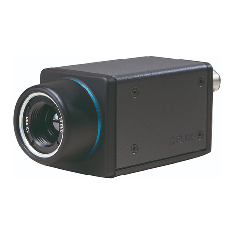
FLIR A300f User manual

User’s manual
FLIR A3xx f series


User’s manual
FLIR A3xx f series
#T559794; r. AJ/35709/35709; en-US iii


Table of contents
1 Legal disclaimer................................................................................1
1.1 Legal disclaimer .......................................................................1
1.2 Usage statistics ........................................................................ 1
1.3 Changes to registry ...................................................................1
1.4 U.S. Government Regulations......................................................1
1.5 Copyright................................................................................1
1.6 Quality assurance .....................................................................1
1.7 Patents...................................................................................1
1.8 EULATerms ............................................................................1
2 Safety information .............................................................................2
3 Notice to user ...................................................................................3
3.1 User-to-user forums ..................................................................3
3.2 Calibration...............................................................................3
3.3 Accuracy ................................................................................3
3.4 Disposal of electronic waste ........................................................3
3.5 Training ..................................................................................3
3.6 Documentation updates .............................................................3
3.7 Important note about this manual..................................................3
3.8 Note about authoritative versions..................................................3
4 Customer help ..................................................................................4
4.1 General ..................................................................................4
4.2 Submitting a question ................................................................4
4.3 Downloads..............................................................................5
5 Introduction......................................................................................6
5.1 FLIR A3xx f series.....................................................................6
6 List of accessories and services .........................................................7
7 Installation .......................................................................................9
7.1 Installation overview ..................................................................9
7.2 Installation components..............................................................9
7.3 Location considerations .............................................................9
7.4 Camera mounting .....................................................................9
7.5 Prior to cutting/drilling holes ...................................................... 10
7.6 Back cover ............................................................................ 11
7.7 Removing the back cover ......................................................... 11
7.8 Connecting power................................................................... 12
7.9 Video connections .................................................................. 12
7.10 Ethernet connection ................................................................ 12
8 Verifying camera operation............................................................... 13
8.1 Power and analog video ........................................................... 13
8.2 IP Communications ................................................................. 13
9 Technical data.................................................................................14
9.1 Online field-of-view calculator .................................................... 14
9.2 Note about technical data ......................................................... 14
9.3 Note about authoritative versions................................................ 14
9.4 FLIR A300f 25°....................................................................... 15
9.5 FLIR A300f 45°....................................................................... 18
9.6 FLIR A310f 15°....................................................................... 21
9.7 FLIR A310f 25°....................................................................... 25
9.8 FLIR A310f 45°....................................................................... 29
9.9 FLIR A310f 6° ........................................................................ 33
9.10 FLIR A310f 90°....................................................................... 37
9.11 FLIR A315f 25°....................................................................... 41
9.12 FLIR A315f 45°....................................................................... 44
9.13 FLIR A315f 90°....................................................................... 47
#T559794; r. AJ/35709/35709; en-US v

Table of contents
10 Mechanical drawings ....................................................................... 50
11 CE Declaration of conformity ............................................................ 60
12 Pin configurations and schematics.................................................... 62
12.1 Pin configuration for camera I/O connector ................................... 62
12.2 Schematic overview of the camera unit digital I/O ports ................... 62
13 Cleaning the camera ........................................................................ 63
13.1 Camera housing, cables, and other items..................................... 63
13.1.1 Liquids....................................................................... 63
13.1.2 Equipment.................................................................. 63
13.1.3 Procedure .................................................................. 63
13.2 Infrared lens .......................................................................... 63
13.2.1 Liquids....................................................................... 63
13.2.2 Equipment.................................................................. 63
13.2.3 Procedure .................................................................. 63
14 About FLIR Systems ........................................................................ 64
14.1 More than just an infrared camera .............................................. 65
14.2 Sharing our knowledge ............................................................ 65
14.3 Supporting our customers......................................................... 65
15 Glossary ........................................................................................67
16 Thermographic measurement techniques .......................................... 70
16.1 Introduction .......................................................................... 70
16.2 Emissivity.............................................................................. 70
16.2.1 Finding the emissivity of a sample.................................... 70
16.3 Reflected apparent temperature................................................. 73
16.4 Distance ............................................................................... 74
16.5 Relative humidity .................................................................... 74
16.6 Other parameters.................................................................... 74
17 History of infrared technology........................................................... 75
18 Theory of thermography................................................................... 78
18.1 Introduction ........................................................................... 78
18.2 The electromagnetic spectrum................................................... 78
18.3 Blackbody radiation................................................................. 78
18.3.1 Planck’s law ................................................................ 79
18.3.2 Wien’s displacement law................................................ 80
18.3.3 Stefan-Boltzmann's law ................................................. 81
18.3.4 Non-blackbody emitters................................................. 82
18.4 Infrared semi-transparent materials............................................. 84
19 The measurement formula................................................................ 85
20 Emissivity tables ............................................................................. 89
20.1 References............................................................................ 89
20.2 Tables .................................................................................. 89
#T559794; r. AJ/35709/35709; en-US vi

Legal disclaimer
1
1.1 Legal disclaimer
All products manufactured by FLIR Systems are warranted against defective
materials and workmanship for a period of one (1) year from the delivery date
of the original purchase, provided such products have been under normal
storage, use and service, and in accordance with FLIR Systems instruction.
Uncooled handheld infrared cameras manufactured by FLIR Systems are
warranted against defective materials and workmanship for a period of two
(2) years from the delivery date of the original purchase, provided such prod-
ucts have been under normal storage, use and service, and in accordance
with FLIR Systems instruction, and provided that the camera has been regis-
tered within 60 days of original purchase.
Detectors for uncooled handheld infrared cameras manufactured by FLIR
Systems are warranted against defective materials and workmanship for a
period of ten (10) years from the delivery date of the original purchase, pro-
vided such products have been under normal storage, use and service, and
in accordance with FLIR Systems instruction, and provided that the camera
has been registered within 60 days of original purchase.
Products which are not manufactured by FLIR Systems but included in sys-
tems delivered by FLIR Systems to the original purchaser, carry the warranty,
if any, of the particular supplier only. FLIR Systems has no responsibility
whatsoever for such products.
The warranty extends only to the original purchaser and is not transferable. It
is not applicable to any product which has been subjected to misuse, neglect,
accident or abnormal conditions of operation. Expendable parts are excluded
from the warranty.
In the case of a defect in a product covered by this warranty the product must
not be further used in order to prevent additional damage. The purchaser
shall promptly report any defect to FLIR Systems or this warranty will not
apply.
FLIR Systems will, at its option, repair or replace any such defective product
free of charge if, upon inspection, it proves to be defective in material or work-
manship and provided that it is returned to FLIR Systems within the said one-
year period.
FLIR Systems has no other obligation or liability for defects than those set
forth above.
No other warranty is expressed or implied. FLIR Systems specifically dis-
claims the implied warranties of merchantability and fitness for a particular
purpose.
FLIR Systems shall not be liable for any direct, indirect, special, incidental or
consequential loss or damage, whether based on contract, tort or any other
legal theory.
This warranty shall be governed by Swedish law.
Any dispute, controversy or claim arising out of or in connection with this war-
ranty, shall be finally settled by arbitration in accordance with the Rules of the
Arbitration Institute of the Stockholm Chamber of Commerce. The place of ar-
bitration shall be Stockholm. The language to be used in the arbitral proceed-
ings shall be English.
1.2 Usage statistics
FLIR Systems reserves the right to gather anonymous usage statistics to help
maintain and improve the quality of our software and services.
1.3 Changes to registry
The registry entry HKEY_LOCAL_MACHINE\SYSTEM\CurrentControlSet
\Control\Lsa\LmCompatibilityLevel will be automatically changed to level 2 if
the FLIR Camera Monitor service detects a FLIR camera connected to the
computer with a USB cable. The modification will only be executed if the
camera device implements a remote network service that supports network
logons.
1.4 U.S. Government Regulations
This product may be subject to U.S. Export Regulations. Please send any in-
1.5 Copyright
© 2016, FLIR Systems, Inc. All rights reserved worldwide. No parts of the
software including source code may be reproduced, transmitted, transcribed
or translated into any language or computer language in any form or by any
means, electronic, magnetic, optical, manual or otherwise, without the prior
written permission of FLIR Systems.
The documentation must not, in whole or part, be copied, photocopied, re-
produced, translated or transmitted to any electronic medium or machine
readable form without prior consent, in writing, from FLIR Systems.
Names and marks appearing on the products herein are either registered
trademarks or trademarks of FLIR Systems and/or its subsidiaries. All other
trademarks, trade names or company names referenced herein are used for
identification only and are the property of their respective owners.
1.6 Quality assurance
The Quality Management System under which these products are developed
and manufactured has been certified in accordance with the ISO 9001
standard.
FLIR Systems is committed to a policy of continuous development; therefore
we reserve the right to make changes and improvements on any of the prod-
ucts without prior notice.
1.7 Patents
One or several of the following patents and/or design patents may apply to
the products and/or features. Additional pending patents and/or pending de-
sign patents may also apply.
000279476-0001; 000439161; 000499579-0001; 000653423; 000726344;
000859020; 001106306-0001; 001707738; 001707746; 001707787;
001776519; 001954074; 002021543; 002058180; 002249953; 002531178;
0600574-8; 1144833; 1182246; 1182620; 1285345; 1299699; 1325808;
1336775; 1391114; 1402918; 1404291; 1411581; 1415075; 1421497;
1458284; 1678485; 1732314; 2106017; 2107799; 2381417; 3006596;
3006597; 466540; 483782; 484155; 4889913; 5177595; 60122153.2;
602004011681.5-08; 6707044; 68657; 7034300; 7110035; 7154093;
7157705; 7237946; 7312822; 7332716; 7336823; 7544944; 7667198;
7809258 B2; 7826736; 8,153,971; 8,823,803; 8,853,631; 8018649 B2;
8212210 B2; 8289372; 8354639 B2; 8384783; 8520970; 8565547; 8595689;
8599262; 8654239; 8680468; 8803093; D540838; D549758; D579475;
D584755; D599,392; D615,113; D664,580; D664,581; D665,004; D665,440;
D677298; D710,424 S; D718801; DI6702302-9; DI6903617-9; DI7002221-6;
DI7002891-5; DI7002892-3; DI7005799-0; DM/057692; DM/061609; EP
2115696 B1; EP2315433; SE 0700240-5; US 8340414 B2; ZL
201330267619.5; ZL01823221.3; ZL01823226.4; ZL02331553.9;
ZL02331554.7; ZL200480034894.0; ZL200530120994.2;
ZL200610088759.5; ZL200630130114.4; ZL200730151141.4;
ZL200730339504.7; ZL200820105768.8; ZL200830128581.2;
ZL200880105236.4; ZL200880105769.2; ZL200930190061.9;
ZL201030176127.1; ZL201030176130.3; ZL201030176157.2;
ZL201030595931.3; ZL201130442354.9; ZL201230471744.3;
ZL201230620731.8.
1.8 EULA Terms
• You have acquired a device (“INFRARED CAMERA”) that includes soft-
ware licensed by FLIR Systems AB from Microsoft Licensing, GP or its
affiliates (“MS”). Those installed software products of MS origin, as well
as associated media, printed materials, and “online” or electronic docu-
mentation (“SOFTWARE”) are protected by international intellectual
property laws and treaties. The SOFTWARE is licensed, not sold. All
rights reserved.
• IF YOU DO NOT AGREE TO THIS END USER LICENSE AGREEMENT
(“EULA”), DO NOT USE THE DEVICE OR COPY THE SOFTWARE. IN-
STEAD, PROMPTLY CONTACT FLIR Systems AB FOR INSTRUC-
TIONS ON RETURN OF THE UNUSED DEVICE(S) FOR A REFUND.
ANY USE OF THE SOFTWARE, INCLUDING BUT NOT LIMITED TO
USE ON THE DEVICE, WILL CONSTITUTE YOUR AGREEMENT TO
THIS EULA (OR RATIFICATION OF ANY PREVIOUS CONSENT).
•GRANT OF SOFTWARE LICENSE. This EULA grants you the following
license:
◦ You may use the SOFTWARE only on the DEVICE.
◦NOT FAULT TOLERANT. THE SOFTWARE IS NOT FAULT TOL-
ERANT. FLIR Systems AB HAS INDEPENDENTLY DETERMINED
HOW TO USE THE SOFTWARE IN THE DEVICE, AND MS HAS
RELIED UPON FLIR Systems AB TO CONDUCT SUFFICIENT
TESTING TO DETERMINE THAT THE SOFTWARE IS SUITABLE
FOR SUCH USE.
◦NO WARRANTIES FOR THE SOFTWARE. THE SOFTWARE is
provided “AS IS” and with all faults. THE ENTIRE RISK AS TO
SATISFACTORY QUALITY, PERFORMANCE, ACCURACY, AND
EFFORT (INCLUDING LACK OF NEGLIGENCE) IS WITH YOU.
ALSO, THERE IS NO WARRANTY AGAINST INTERFERENCE
WITH YOUR ENJOYMENT OF THE SOFTWARE OR AGAINST
INFRINGEMENT. IF YOU HAVE RECEIVED ANY WARRANTIES
REGARDING THE DEVICE OR THE SOFTWARE, THOSE WAR-
RANTIES DO NOT ORIGINATE FROM, AND ARE NOT BINDING
ON, MS.
◦ No Liability for Certain Damages. EXCEPT AS PROHIBITED BY
LAW, MS SHALL HAVE NO LIABILITY FOR ANY INDIRECT,
SPECIAL, CONSEQUENTIAL OR INCIDENTAL DAMAGES
ARISING FROM OR IN CONNECTION WITH THE USE OR PER-
FORMANCE OF THE SOFTWARE. THIS LIMITATION SHALL
APPLY EVEN IF ANY REMEDY FAILS OF ITS ESSENTIAL PUR-
POSE. IN NO EVENT SHALL MS BE LIABLE FOR ANY
AMOUNT IN EXCESS OF U.S. TWO HUNDRED FIFTY DOL-
LARS (U.S.$250.00).
◦Limitations on Reverse Engineering, Decompilation, and Dis-
assembly. You may not reverse engineer, decompile, or disas-
semble the SOFTWARE, except and only to the extent that such
activity is expressly permitted by applicable law notwithstanding
this limitation.
◦SOFTWARE TRANSFER ALLOWED BUT WITH RESTRIC-
TIONS. You may permanently transfer rights under this EULA only
as part of a permanent sale or transfer of the Device, and only if
the recipient agrees to this EULA. If the SOFTWARE is an up-
grade, any transfer must also include all prior versions of the
SOFTWARE.
◦EXPORT RESTRICTIONS. You acknowledge that SOFTWARE is
subject to U.S. export jurisdiction. You agree to comply with all ap-
plicable international and national laws that apply to the SOFT-
WARE, including the U.S. Export Administration Regulations, as
well as end-user, end-use and destination restrictions issued by U.
S. and other governments. For additional information see http://
www.microsoft.com/exporting/.
#T559794; r. AJ/35709/35709; en-US 1
Safety information
2
WARNING
Make sure that you read all applicable MSDS (Material Safety Data Sheets) and warning labels on con-
tainers before you use a liquid. The liquids can be dangerous. Injury to persons can occur.
CAUTION
Do not point the infrared camera (with or without the lens cover) at strong energy sources, for example,
devices that cause laser radiation, or the sun. This can have an unwanted effect on the accuracy of the
camera. It can also cause damage to the detector in the camera.
CAUTION
Do not use the camera in temperatures more than +50°C (+122°F), unless other information is specified
in the user documentation or technical data. High temperatures can cause damage to the camera.
CAUTION
Do not apply solvents or equivalent liquids to the camera, the cables, or other items. Damage to the bat-
tery and injury to persons can occur.
CAUTION
Be careful when you clean the infrared lens. The lens has an anti-reflective coating which is easily dam-
aged. Damage to the infrared lens can occur.
CAUTION
Do not use too much force to clean the infrared lens. This can cause damage to the anti-reflective
coating.
CAUTION
Applicability: Cameras with an automatic shutter that can be disabled.
Do not disable the automatic shutter in the camera for a long time period (a maximum of 30 minutes is
typical). If you disable the shutter for a longer time period, damage to the detector can occur.
NOTE
The encapsulation rating is only applicable when all the openings on the camera are sealed with their
correct covers, hatches, or caps. This includes the compartments for data storage, batteries, and
connectors.
CAUTION
Applicability: Cameras where you can remove the lens and expose the infrared detector.
Do not use the pressurized air from the pneumatic air systems in a workshop when you remove dust
from the detector. The air contains oil mist to lubricate the pneumatic tools and the pressure is too high.
Damage to the detector can occur.
#T559794; r. AJ/35709/35709; en-US 2

Notice to user
3
3.1 User-to-user forums
Exchange ideas, problems, and infrared solutions with fellow thermographers around the
world in our user-to-user forums. To go to the forums, visit:
http://www.infraredtraining.com/community/boards/
3.2 Calibration
We recommend that you send in the camera for calibration once a year. Contact your lo-
cal sales office for instructions on where to send the camera.
3.3 Accuracy
For very accurate results, we recommend that you wait 5 minutes after you have started
the camera before measuring a temperature.
3.4 Disposal of electronic waste
As with most electronic products, this equipment must be disposed of in an environmen-
tally friendly way, and in accordance with existing regulations for electronic waste.
Please contact your FLIR Systems representative for more details.
3.5 Training
To read about infrared training, visit:
• http://www.infraredtraining.com
• http://www.irtraining.com
• http://www.irtraining.eu
3.6 Documentation updates
Our manuals are updated several times per year, and we also issue product-critical notifi-
cations of changes on a regular basis.
To access the latest manuals and notifications, go to the Download tab at:
http://support.flir.com
It only takes a few minutes to register online. In the download area you will also find the
latest releases of manuals for our other products, as well as manuals for our historical
and obsolete products.
3.7 Important note about this manual
FLIR Systems issues generic manuals that cover several cameras within a model line.
This means that this manual may contain descriptions and explanations that do not apply
to your particular camera model.
3.8 Note about authoritative versions
The authoritative version of this publication is English. In the event of divergences due to
translation errors, the English text has precedence.
Any late changes are first implemented in English.
#T559794; r. AJ/35709/35709; en-US 3

Customer help
4
4.1 General
For customer help, visit:
http://support.flir.com
4.2 Submitting a question
To submit a question to the customer help team, you must be a registered user. It only
takes a few minutes to register online. If you only want to search the knowledgebase for
existing questions and answers, you do not need to be a registered user.
When you want to submit a question, make sure that you have the following information
to hand:
• The camera model
• The camera serial number
• The communication protocol, or method, between the camera and your device (for ex-
ample, HDMI, Ethernet, USB, or FireWire)
• Device type (PC/Mac/iPhone/iPad/Android device, etc.)
• Version of any programs from FLIR Systems
• Full name, publication number, and revision number of the manual
#T559794; r. AJ/35709/35709; en-US 4

Customer help
4
4.3 Downloads
On the customer help site you can also download the following, when applicable for the
product:
• Firmware updates for your infrared camera.
• Program updates for your PC/Mac software.
• Freeware and evaluation versions of PC/Mac software.
• User documentation for current, obsolete, and historical products.
• Mechanical drawings (in *.dxf and *.pdf format).
• Cad data models (in *.stp format).
• Application stories.
• Technical datasheets.
• Product catalogs.
#T559794; r. AJ/35709/35709; en-US 5

Introduction
5
5.1 FLIR A3xx f series
Figure 5.1 FLIR A3xx f series camera
The main function of the FLIR A3xx f series camera is, through adding the housing, to in-
crease the environmental specification of the standard FLIR A3xx f series camera to IP
66 without affecting any of the features available in the camera itself.
The built-in FLIR A3xx f series camera offers an affordable and accurate temperature
measurement solution for anyone who needs to solve problems that do not call for the
highest speed or reaction and who uses a PC. Due to its composite video output, it is al-
so an excellent choice for thermal image automation applications, where you can utilize
its unique properties such as looking through steam.
Key features:
• MPEG-4 streaming.
• PoE (Power over Ethernet).
• Built-in web server.
• General purpose I/O.
• 100 Mbps Ethernet (100 m cable, wireless, fiber, etc.).
• Synchronization through SNTP.
• Composite video output.
• Multi-camera utility software: FLIR IP Config and FLIR IR Monitor included.
• Open and well-described TCP/IP protocol for control and set-up.
• 16-bit 320 × 240 images @ 3 Hz, radiometric.
• Multi-camera software: FLIR Sensors Manager allows users to manage and control a
FLIR A3xx f series camera in a TCP/IP network.
Typical applications:
• Fire prevention, critical vessel monitoring, and power utility asset management.
• Volume-oriented industrial control (multi-camera installation is possible).
#T559794; r. AJ/35709/35709; en-US 6

List of accessories and services
6
Product name Part number
Ethernet cable CAT-6, 2m/6.6 ft. T951004ACC
FLIR IR Camera Player DSW-10000
FLIR Sensors Manager, pro 4130235
FLIR Tools T198584
FLIR Tools Mobile (Android Application) APP-10002
FLIR Tools Mobile (iPad/iPhone Application) APP-10003
FLIR Tools+ (license only) T198583
HARD CASE - WITH FOAM, F - SERIES 324-0004-00
High temp. option +1200°C/+2192°F for FLIR T/
B2xx to T/B4xx and A3xx, A3xxf, A3xxpt, A3xxsc
series
T197000
ITC Advanced General Thermography Course -
attendance, 1 pers.
ITC-ADV-3021
ITC Advanced General Thermography Course-
group of 10 pers.
ITC-ADV-3029
ITC Advanced Thermal applications course - at-
tendance 1 pers. (3 days)
ITC-ADV-3061
ITC Advanced Thermal applications course -
group up to 10 pers. (3 days)
ITC-ADV-3069
ITC Automated safety systems training - attend-
ance 1 pers (3 days)
ITC-AUT-3101
ITC Automated safety systems training - group of
up to 10 pers (3 days)
ITC-AUT-3109
ITC conference fee ITC-CON-1001
ITC Customized workshop - per person (per day) ITC-EXP-1041
ITC In-house training - additional attendance 1
pers. (per day)
ITC-EXP-1021
ITC In-house training - group up to 10 pers. (per
day)
ITC-EXP-1029
ITC Infrared application and system consultancy
(per day)
ITC-EXP-1050
ITC Level 1 Thermography Course - additional
student to on site class, 1 pers
ITC-CER-5105
ITC Level 1 Thermography Course - attendance,
1 pers.
ITC-CER-5101
ITC Level 1 Thermography Course – group of 10
pers.
ITC-CER-5109
ITC Level 2 Thermography Course - additional
student to on site class, 1 pers
ITC-CER-5205
ITC Level 2 Thermography Course - attendance,
1 pers.
ITC-CER-5201
ITC Level 2 Thermography Course – group of 10
pers.
ITC-CER-5209
ITC R&D basics for industry users - group up to 6
pers. (2 days)
ITC-EXP-2036
ITC Short course Fever Screening - additional stu-
dent to on site class (2 days)
ITC-EXP-2025
ITC Short course Fever Screening - attendance 1
pers. (2 days)
ITC-EXP-2021
ITC Short course Fever Screening - inclusive 10
pers. (2 days)
ITC-EXP-2029
#T559794; r. AJ/35709/35709; en-US 7

List of accessories and services
6
Product name Part number
ITC Short course Introduction to thermography -
inclusive 10 pers. (1 day)
ITC-EXP-1019
ITC Short course Introduction to thermography
-attendance 1 pers. (1 day)
ITC-EXP-1011
ITC Software course - attendance 1 pers. (per
day)
ITC-SOW-0001
ITC Software course - group up to 10 pers. (per
day)
ITC-SOW-0009
ITC Training 1 day - attendance 1 pers. ITC-EXP-1001
ITC Training 1 day - group up to 10 pers. ITC-EXP-1009
ITC Training 2 days - attendance 1 pers. ITC-EXP-2001
ITC Training 2 days - group up to 10 pers. ITC-EXP-2009
ITC Training 3 days - attendance 1 pers. ITC-EXP-3001
ITC Training 3 days - group up to 10 pers. ITC-EXP-3009
ITC travel time for instructor ITC-TFT-0100
PEDESTAL MOUNT ASSY - F-SERIES 500-0463-00
POLE ADAPTER - F-SERIES 4119507
Power cable, pigtailed 1910586ACC
Power supply for A3xx f, IP66 T911182
ThermoVision™ LabVIEW® Digital Toolkit Ver.
3.3
T198566
ThermoVision™ System Developers Kit Ver. 2.6 T198567
Travel and lodging expenses instructor (Center
and South Africa)
ITC-TOL-1003
Travel and lodging expenses instructor (Europe,
Balcans, Turkey, Cyprus)
ITC-TOL-1001
Travel and lodging expenses instructor (other) ITC-TOL-1005
Travel and lodging expenses instructor (Russia/
GUS, Middle East, North Africa)
ITC-TOL-1002
Travel and lodging expenses instructor (various) ITC-TOL-1004
Video cable, 3.0 m/9.8 ft. 908929
WALL MOUNT ASSY - F-SERIES 500-0462-00
Note FLIR Systems reserves the right to discontinue models, parts or accessories,
and other items, or to change specifications at any time without prior notice.
#T559794; r. AJ/35709/35709; en-US 8

Installation
7
7.1 Installation overview
Figure 7.1 FLIR A3xx f series camera
The FLIR A3xx f series camera is an infrared thermal imaging camera intended for out-
door applications, and can be installed in a fixed location or on a pan/tilt mechanism.
The FLIR A3xx f series camera is intended to be mounted on a medium-duty fixed ped-
estal mount or wall mount commonly used in the CCTV industry. Cables will exit from the
back of the camera housing. The mount must support up to 30 lbs. (15 kg).
The FLIR A3xx f series camera is both an analog camera and an IP camera. The video
from the camera can be viewed over a traditional analog video network or it can be
viewed by streaming it over an IP network using MPEG-4 encoding. Analog video will re-
quire a connection to a video monitor or an analog matrix/switch. The IP video will require
a connection to an Ethernet network switch, and a computer with the appropriate soft-
ware for viewing the video.
The camera can be controlled through IP communications.
The camera operates on 12/24 VDC, 9 W max. (allowed range: 10–30 VDC) and heaters
on 24 VDC, 25 W max. In total: 34 W.
In order to access the electrical connections and install the cables, it is necessary to tem-
porarily remove the back cover of the camera housing.
7.2 Installation components
In addition to the items included in the cardboard box, the installer will need to supply the
following items:
• Electrical wire, for system power: up to 100′ (three conductor, shielded, gauge deter-
mined by cable length and supply voltage).
• Camera grounding strap.
• Coaxial RG59U video cables (BNC connector at the camera end) for analog video.
• Shielded Category 6 Ethernet cable for control and streaming video over an IP net-
work; and also for software upgrades.
• Miscellaneous electrical hardware, connectors, and tools.
7.3 Location considerations
The camera will require connections for power, communications (IP Ethernet, and/or RS-
232/RS-422), and video.
Note Install all cameras with an easily accessible Ethernet connection, to support fu-
ture software upgrades.
Ensure that cable distances do not exceed the referenced standard specifications and
adhere to all local and Industry standards, codes, and best practices.
7.4 Camera mounting
FLIR A3xx f series cameras must be mounted upright on top of the mounting surface,
with the base below the camera. The unit should not be hung upside down.
The FLIR A3xx f series camera can be secured to the mount with three to five ¼″-20
bolts or studs, as shown below.
#T559794; r. AJ/35709/35709; en-US 9

Installation
7
Note Use washers to protect the painting.
Once the mounting location has been selected, verify that both sides of the mounting
surface are accessible.
Figure 7.2 FLIR A3xx f series camera mounting (mm)
If the camera is to be mounted on a pole or tower or other hard-to-reach location, con-
nect and operate the camera as a bench test at ground level prior to mounting the cam-
era in its final location.
Use a thread-locking compound such as Loctite 242 or an equivalent with all metal-to-
metal threaded connections.
Using the template supplied with the camera as a guide, mark the location of the holes
for mounting the camera.
If the template is printed, ensure that it is printed to scale so that the dimensions are
correct.
Once the holes are drilled in the mounting surface, install three (3) to five (5) ¼″-20 bolts
or threaded studs in the base of the camera with thread-locking compound.
7.5 Prior to cutting/drilling holes
When selecting a mounting location for the FLIR A3xx f series camera, consider cable
lengths and cable routing. Ensure that the cables are long enough, given the proposed
mounting locations and cable routing requirements, and route the cables before you in-
stall the components.
Use cables that have sufficient dimensions to ensure safety (for power cables) and ad-
equate signal strength (for video and communications).
#T559794; r. AJ/35709/35709; en-US 10

Installation
7
7.6 Back cover
Figure 7.3 Back cover of a FLIR A3xx f series camera.
1. Breather valve.
2. Ground lug.
3. Shipping plug.
4. Mounting screw (×4).
5. Shipping plug.
The FLIR A3xx f series camera comes with two ¾″ NPTcable glands, each with a three-
hole gland seal insert. Cables can be between 0.23″ and 0.29″ OD. Typically, up to five
cables may be needed. Plugs are required for any insert hole(s) not being used.
Figure 7.4 ¾″ NPTcable gland.
If non-standard cable diameters are used, you may need to locate or fabricate the appro-
priate insert to fit the desired cable. FLIR Systems does not provide cable gland inserts
other than what is supplied with the system.
Insert the cables through the cable glands on the enclosure before terminating and con-
necting them. (In general, the terminated connectors will not fit through the cable gland.)
If a terminated cable is required, make a single clean cut in the gland seal to install the
cable into the gland seal.
Proper installation of cable sealing glands and use of appropriate elastomer inserts is
critical to long-term reliability. Cables enter the camera mount enclosure through liquid-
tight compression glands. Be sure to insert the cables through the cable glands on the
enclosure before terminating and connecting them (the connectors will not fit through the
cable gland). Leave the gland nuts loosened until all cable installation has been com-
pleted. Inspect and install gland fittings in the back cover with suitable leak sealant, and
tighten to ensure water-tight fittings. PTFE tape or pipe sealant (e.g., DuPont RectorSeal
T) is suitable for this purpose.
7.7 Removing the back cover
Use a 3 mm hex key to loosen the screws, exposing the connections at the back of the
camera enclosure. There is a grounding wire connected between the case and the back
cover as shown.
#T559794; r. AJ/35709/35709; en-US 11

Installation
7
Figure 7.5 Rear view of a FLIR A3xx f series camera, after the back cover has been removed.
1. Camera power.
2. Camera heater.
3. Video.
4. I/O ports.
5. Ethernet.
7.8 Connecting power
The camera operates on 12/24 VDC, 9 W max. (allowed range: 10–30 VDC) and heaters
on 24 VDC, 25 W max. In total: 34 W.
The camera itself does not have an on/off switch. Generally, the FLIR A3xx f series cam-
era will be connected to a circuit breaker, and the circuit breaker will be used to connect
or interrupt the power supply to the camera. If power is supplied to it, the camera will be
in one of two modes: Booting Up or Powered On.
The power cable supplied by the installer must use wires that are of a sufficient gauge
size (16 AWG is recommended) for the supply voltage and length of the cable run, to en-
sure adequate current-carrying capacity. Always follow local building codes.
Ensure that the camera is properly grounded. Typical to good grounding practices, the
camera chassis ground should be provided using the lowest resistance path possible.
FLIR Systems requires using a grounding strap anchored to the grounding lug on the
back plate of the camera housing and connected to the nearest earth-grounding point.
Note The terminal blocks for power connections will accept a maximum 16 AWG wire
size.
7.9 Video connections
The analog video connection on the back of the camera is a BNC connector. The camera
also provides an RCA video connector that can be used to temporarily monitor the video
output, without disconnecting the BNC connection.
The video cable used should be rated as RG59U or better to ensure a quality video
signal.
7.10 Ethernet connection
The cable gland seal is designed for use with shielded Category 6 Ethernet cable.
#T559794; r. AJ/35709/35709; en-US 12

Verifying camera operation
8
Prior to installing the camera, use a bench test to verify camera operation and to config-
ure the camera for the local network.
8.1 Power and analog video
Follow this procedure:
1. Connect the power and video cables to the camera.
2. Connect the video cable from the camera to a display/monitor, and connect the
power cable to a power supply. The camera operates on 12/24 VDC, 9 W max. (al-
lowed range: 10–30 VDC) and heaters on 24 VDC, 25 W max. In total: 34 W. Verify
that video output is displayed on the monitor.
3. Use an Ethernet cable to connect the camera either directly to a computer or to a
router that is connected to the same network as the computer.
4. Close down all applications on the computer.
5. Insert the CD-ROM into the CD drive on the computer. The installation should start
automatically.
Should the installation not start automatically, start Windows Explorer and double-
click SETUP.HTM on the CD-ROM.
6. Click one of the following:
•Install (for all FLIR A3xx f series cameras).
•Install ( for series cameras).
•Install (for and series cameras).
Note For series cameras, you can use to set up and control the camera. For more
information, see section , page . Use to identify the unit in the network and set the IP
address if necessary.
7. Follow the on-screen instructions.
8.2 IP Communications
It is assumed that a FLIR A3xx f system will be set up on an existing network and be as-
signed an IP address from the DHCP server.
#T559794; r. AJ/35709/35709; en-US 13

Technical data
9
9.1 Online field-of-view calculator
Please visit http://support.flir.com and click the photo of the camera series for field-of-
view tables for all lens–camera combinations.
9.2 Note about technical data
FLIR Systems reserves the right to change specifications at any time without prior notice.
Please check http://support.flir.com for latest changes.
9.3 Note about authoritative versions
The authoritative version of this publication is English. In the event of divergences due to
translation errors, the English text has precedence.
Any late changes are first implemented in English.
#T559794; r. AJ/35709/35709; en-US 14
This manual suits for next models
2
Table of contents
Other FLIR Thermographic Camera manuals

FLIR
FLIR A50 Series User manual

FLIR
FLIR T600-NIST User manual

FLIR
FLIR Navigator II User manual

FLIR
FLIR T8 Series User manual

FLIR
FLIR GF300 User manual

FLIR
FLIR X6520sc Series User manual

FLIR
FLIR A3 PT series User manual

FLIR
FLIR EX Series User manual

FLIR
FLIR Extech i5 User manual

FLIR
FLIR ThermaCAM P65 User manual