Flomec Oval Gear User manual

Industrial Oval Gear Flowmeters
with pulse output or electronic display
Operation Manual
2
General Information
This manual provides the necessary information for installation of your Oval Gear
flowmeter; for information on any integral electronics or accessories fitted to your
flowmeter please consult the relevant electronics or accessory manual. Your Oval Gear
flowmeter should only be installed by persons familiar with local regulations, particularly
those for workplace Health and Safety, or Hazardous Area regulations where relevant.
For best results, please make yourself familiar with the contents of all relevant product
manuals prior to installation and commissioning. If further assistance is required please
consult the distributor from whom you purchased your flowmeter.
DISPOSAL WITHIN THE EUROPEAN UNION - WEEE
Your flow-meter and any associated electronics are precision instruments,
to avoid unnecessary damage please treat them with care.
CAUTION
•
The WEEE Directive requires that this product be recycled
when disposed of within the European Union
•The crossed out wheelie bin symbol shown in this manual
signifies that this product should not be disposed of in general
waste or landfill.
•Please contact the local dealer or national distributor from
whom this product was purchased for information on recycling
electronic equipment within your region.

3
Table of Contents
1. Introduction............................................................................................................... 5
1.1 Operating Principle .......................................................................................................5
1.2 Specifications ................................................................................................................6
2. Installation................................................................................................................. 8
2.1 Mechanical Installation.................................................................................................8
2.1.1 Installation Orientation.................................................................................................8
2.1.2 Piping Construction.......................................................................................................9
2.1.3 Mechanical Support......................................................................................................9
2.1.4 Filtration / Straining....................................................................................................10
2.1.5 Pipe Connections.........................................................................................................10
2.2 Electrical Installation ..................................................................................................11
2.2.1 Wiring .........................................................................................................................11
2.2.2 Hall Effect Outputs......................................................................................................11
2.2.3 Reed Switch Outputs...................................................................................................12
2.2.4 Quadrature Pulse Outputs ..........................................................................................13
2.3 Making Electrical Connections....................................................................................13
2.4 Wiring Diagrams.........................................................................................................14
2.4.1 Standard Pulse Output Board .....................................................................................14
2.4.2 Reed Only Pulse Output Board....................................................................................16
2.4.3 Reed Only Outputs as Simple Apparatus.....................................................................17
2.4.4 Hall Only Output .........................................................................................................18
2.4.5 Quadrature Pulse Output............................................................................................19
2.5 Meter Calibration Factor (K-Factor, Scale Factor)
.......................................................19
2.6 Integral Instruments ...................................................................................................19
2.7 Installations in Hazardous Areas.................................................................................20
2.7.1 ATEX/IECEx Flameproof Flowmeters (Ex db)...............................................................20
2.7.2 Conforming Standards ................................................................................................21
2.7.3 Temperature Limits for Flameproof Flowmeters ........................................................22
2.7.4 Special Conditions of Use ............................................................................................22
2.7.5 Earthing of Flameproof Flowmeters ...........................................................................23
2.7.6 Intrinsically Safe Flowmeters (EX i) .............................................................................24
2.8 Commissioning............................................................................................................25
2.9 Fault Finding ...............................................................................................................26
2.10 Troubleshooting Guide................................................................................................27
3. Maintenance and Repairs......................................................................................... 28
3.1 Parts Identification......................................................................................................29
3.2 Flowmeter Disassembly ..............................................................................................31
3.3 Flowmeter Inspection..................................................................................................31
3.4 Re-assembly of Flowmeter..........................................................................................32
4. EC Declaration of Conformity ................................................................................... 33

4
Quick Start Guide
The ‘quick start’ instructions shown below are intended for users who are experienced in
the use of flowmeters and who want to quickly set up their new meter with limited
functionality, and start using their product right away. The ‘quick start’ instructions will
allow the user to set up their meter without the risk of damage, allowing the use of the
product while the complete instructions are read in detail at a later date.
Users installing product in Hazardous Areas must read this entire manual
before installing their product.
Damage caused to meters by users who have only read the ‘Quick Start Guide’
will not be accepted as a justification for a warranty claim; if you are unsure,
read the whole manual before installing your meter.
CAUTION
5
1. Introduction
The Oval gear meter is a precise positive displacement flowmeter incorporating a pair of
oval geared rotors. These meters are capable of measuring the flow of a broad range of
clean liquids.
Stainless Steel flowmeters are suited to most liquid products and chemicals; including
many water based liquids, acids, bases and salt solutions, and Aluminium meters are
suitable for fuels, oils & most non-aggressive lubricating liquids.
Oval Gear flowmeters are available as blind meters with a pulse signal output capable of
interfacing to most monitoring and control instrumentation, or the meter can be fitted with
instruments such as totalisers, rate totalisers or batch controllers. These instruments also
have monitoring and control output options including 4-20mA, scaled pulse, flow-rate
alarms and batch control logic (preset metering).
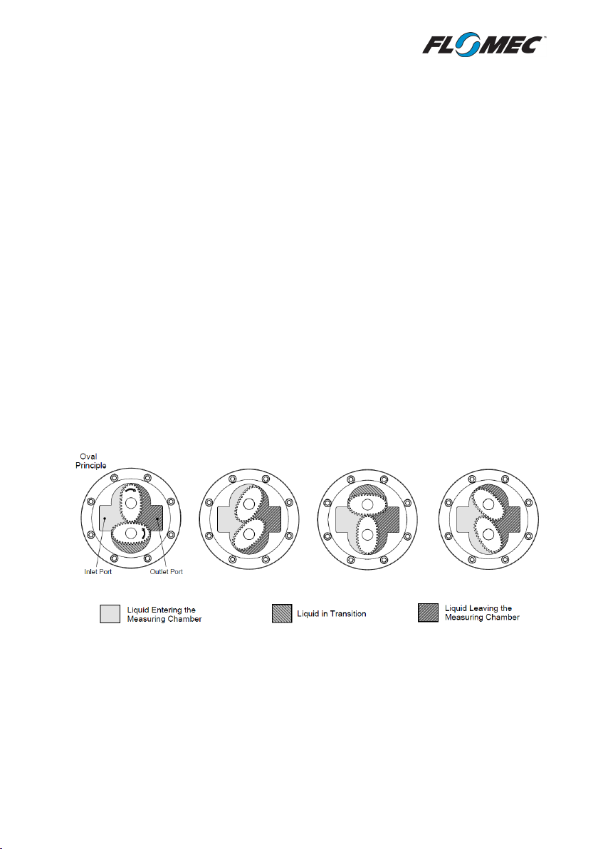
1.1 Operating Principle
Oval Gear flowmeters are positive displacement devices where the passage of liquid
causes two oval geared rotors to rotate within a precision measuring chamber. Each
rotation of the Oval rotors will transmit 4 identical volumes of liquid from the meter inlet to
outlet (as shown in the diagram below); providing electronic pulses via magnetic sensors to
a digital instrument.

6
1.2 Specifications
1.2.1 Small Capacity Models
Model Prefix
004
006
008
Nominal Size
1/8” (4mm)
1/4” (6mm)
3/8” (8mm)1
Flow range2(USG/hr)
0.26 ~ 9.5
0.5 ~ 27
4 ~ 145
Flow range2(L/hr)
1.0 ~ 36
2 ~ 100
15 ~ 550
Accuracy ( liquids ≥ 3cP)
± 1% of reading (± 0.2% with optional RT14)3
Repeatability (liquids ≥ 3cP)
Typically ± 0.03%
Temperature Range
-4oF ~ +250oF (-20oC ~ +120oC)4
Pressure Ratings – PSI (Bar) – threaded meters only 5
Aluminium
220 (15)
Stainless Steel
495 (34)
Intermediate Pressure SS
1450 (100)
High Pressure Models
5800 (400)
Nominal Output Pulse Resolution – Pulses/USG (Pulses/Litre)
Hall Effect
21200 (2800)
7950 (2100)
2690 (710)
Reed Switch
10600 (2800)
7950 (2100)
1345 (355)
High-Resolution Hall Option
42400 (11200)
15900 (4200)
-
Minimum Filtration
200 mesh (75 micron)6
1.2.2 Medium Capacity Models
Model Prefix
015
025
040
050
Nominal Size
1/2" (15mm)
1” (25mm)
1.5” (40mm)
2” (50mm)
Flow range2(USG/min)
0.26 ~ 10.6
2.6 ~ 40
4 ~ 66
8 ~ 120
Flow range2(L/min)
1 ~ 40
10 ~ 150
15 ~ 250
30 ~ 450
Accuracy (liquids≥3cP)
± 0.5% of reading (± 0.2% with optional RT14)3
Repeatability
(liquids≥3cP)
Typically ± 0.03%
Temperature Range
-4oF ~ +250oF (-20oC ~ +120oC)4
Pressure Ratings – PSI (Bar) – threaded meters only 5
Aluminium
990 (68)
990 (68)
435 (30)
285 (20)
Intermediate Pressure
Aluminium
- 2000 (138)- -
Stainless Steel
990 (68)
990 (68)
435 (30)
550 (38)
PPS (Ryton®)
-
73 (5)
-
-
Intermediate Pressure
Stainless Steel
1450 (100)1450 (100) 725 (50) 725 (50)
High Pressure Stainless
Steel
5800 (400) 5800 (400) 5800 (400) 4350 (300)
Nominal Output Pulse Resolution – Pulses/USG (Pulses/Litre)
Hall Effect
636 (168)
405 (107)
212 (56)
99 (26)
Reed Switch
318 (84)
102 (27)
53 (14)
25 (6.5)
Quadrature Hall Option
636 (168)
204 (54)
106 (28)
49 (13)
Minimum Filtration
100 mesh (150 micron)6

7
1.2.3 Large Capacity Models
Model Prefix
080
080E
100
100E
Nominal Size
3” (80mm)
3” (80mm)
4” (100m)
4” (100mm)
Flow range2(USG/min)
10 ~ 200
13 ~ 260
20 ~ 400
40 ~ 660
Flow range2(L/min)
35 ~ 750
50 ~ 1000
75 ~ 1500
150 ~ 2500
Accuracy (liquids ≥ 3cP)
± 0.5% of reading (± 0.2% with optional RT14)3
Repeatability (liquids ≥3cP)
Typically ± 0.03%
Temperature Range
-4oF ~ +250oF (-20oC ~ +120oC)4
Pressure Ratings – PSI (Bar) – threaded meters only 5
Aluminium
175 (12)
175 (12)
145 (10)
145 (10)
Stainless Steel
175 (12)
-
-
-
Nominal Output Pulse Resolution – Pulses/USG (Pulses/Litre)
Hall Effect
40 (10.65)
22.7 (6.0)
16.6 (4.4)
8.5 (2.24)
Reed Switch
10 (2.65)
5.7 (1.5)
4.15 (1.1)
2.1 (0.56)
Quadrature Hall Option
20 (5.33)
11.4 (3.0)
8.3 (2.2)
4.24 (1.12)
Minimum Filtration
40 mesh (350 micron)6
1. OM008H meter have a nominal port size of ¼” (6mm)
2. Maximum flow rate must be reduced with increased viscosity, maintain maximum pressure drop across the
meter at below 14.5psi (1 Bar)
3. 0.2% accuracy achievable using RT14 with non-linearity correction and multi-point calibration.
4. Temperature range stated for standard pulse output meters; higher and lower temperature rating options are
available. Meters fitted with integral instruments will have a reduced maximum temperature. OM008 meters
fitted with PPS rotors are limited to +176oF (+80oC).
5. Flanged meter pressure rating is in accordance with applicable flange standard, or with threaded meter
rating, whichever is lower.
6. Filtration requirements are for soft particles only; hard particles of any size are not acceptable.
1.2.4 Electrical Specifications
Standard Pulse Output Board
Hall Effect Output
Output Type
NPN Open Collector
Voltage Range
5 ~ 24V (dc)
Current Draw
20mA Maximum
Switching Current
10mA Maximum
Reed Switch Output
Output Type
Contact Closure
Voltage
24V (dc) Maximum
Current
50mA Maximum
Recommended
Maximums for
Long Switch Life
5V (dc) @ 10mA
Reed Only Option (Intrinsically Safe Simple Apparatus)
Reed Switch Output
(per switch)
Voltage
24V (dc) Maximum1
Current
16mA Maximum2
Power
0.4W Maximum3
1. 30V (dc) maximum peak voltage allowed for non-hazardous (safe area) installations
2. Up to 200mA possible with internal current limit bypassed (not recommended, safe area only)
3. Up to 6W possible with internal current limit bypassed (not recommended, safe area only)

8
2. Installation
All flowmeters are inspected and calibrated prior to shipment, and are sent out in perfect
condition. Should damage be present on receipt of the product please inspect the delivery
packaging for visible mishandling and contact the parcel service / freight forwarder.
Maintain any protective plugs/caps until installation.
2.1 Mechanical Installation
Before installing your flowmeter, it is recommended that you confirm the meter is
suitable for your application conditions such as; fluid compatibility with meter materials,
flow rate, pressure, and temperature. Fluid entering the meter must remain a liquid at all
times; avoid solidification or gelling of the metered medium. If hydraulic shock or pressure
surges of any kind are possible, the system upstream of the meter must be fitted with a
surge suppressor or pressure relief valve to protect the meter from damage.
2.1.1 Installation Orientation
The flowmeter MUST be mounted with the rotor shafts in a horizontal plane. Failure to
mount your Oval Gear flowmeter in the correct orientation (as shown in the diagrams
below)will cause the weight of the rotors to bear down on the thrust bearings. The short
term effects of incorrect mounting orientation will be a loss in accuracy, with long term
effects ranging from reduced lifespan to fairly rapid catastrophic damage.
Liquid can flow in a horizontal direction, or a vertical direction, but in each case the rotor
shafts must be in a horizontal plane. This is achieved by mounting the meter so that the
terminal cover, or integral instrument display, is facing in a horizontal direction. For pulse
output flowmeters the direction of flow is not important, as the output is non-directional.
Please note that all flow-meters are calibrated with either Castrol ISO4113
or Exxsol D130 immediately prior to shipment, residual oil may be present;
please take the appropriate precautions for health and safety. An MSDS is
available from the manufacturer or via an internet search.
CAUTION
9
2.1.2 Piping Construction
It is preferred to install the flowmeter upstream of a flow control or shut-off valve, as the
back pressure provided by the valve will be beneficial to system accuracy; do not operate a
flowmeter directly discharging to atmosphere. Piping should be designed so that the
flowmeter is full of liquid at all times; this is achieved by designing the inlet and outlet
piping for the flowmeter to be lower than all surrounding piping.
For vertical installations the liquid should travel from bottom to top, i.e. it should rise
vertically through the flowmeter. This will ensure that the flowmeter remains full of liquid
and will stop air entrapment in the meter.
All piping surrounding your flowmeter should be well supported on secure footings,
preferably at the point where the piping joins to the flowmeter; unsupported piping will
cause severe pipe stress on the flowmeter.
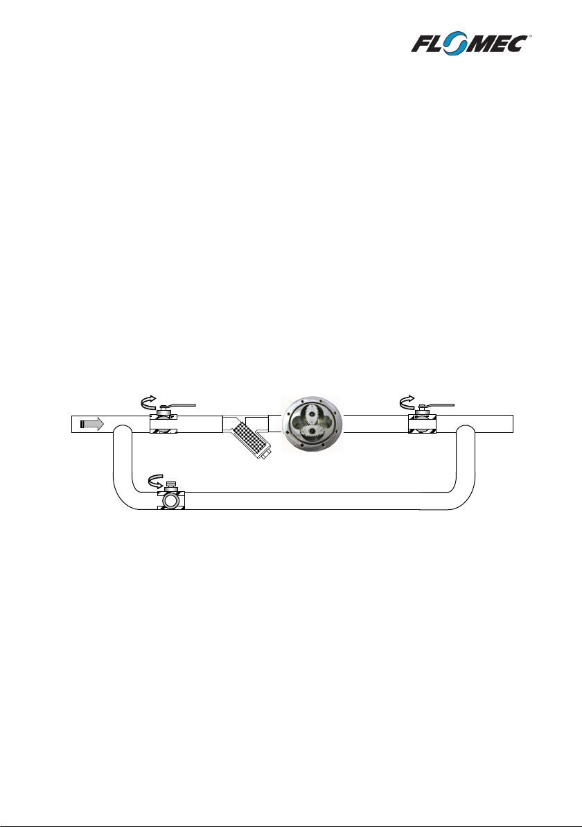
The best piping designs provide a bypass line, as shown in the following diagram, which
allows isolation of the flowmeter and strainer from the main process line. The benefits of
installing a bypass line are that your system can be purged before start-up, and any
maintenance on the flowmeter or strainer can be carried out quickly and economically
without interrupting critical processes.
2.1.3 Mechanical Support
All flowmeters of nominal size 3” and 4” must have adequate mechanical support. Failure to
adequately support the flowmeter and the connected piping may result in structural damage
to the flowmeter housing. It is recommended that a solid structural support be provided at the
first flange connection, on both sides of the flowmeter. If possible, the housing of the
flowmeter can be directly supported, however piping should still be supported as close as
possible to the flowmeter. It is never acceptable to support the flowmeter and use the housing
of the flowmeter to support the weight of your piping.
Strainer
Flowmeter
Isolation valve
Isolation valve
By-pass valve

10
2.1.4 Filtration / Straining
It is recommended to fit the inlet side of your flowmeter directly to a strainer of
appropriate pipe size and mesh size. The minimum mesh size as shown in the specifications
section of this manual should be adhered to where ever possible. When metering medium
or high viscosity fluids it may be necessary to use a strainer one pipe size larger than the
flowmeter nominal size, in order to limit the pressure drop across the strainer basket and
maintain strainer efficiency (i.e. a 1.5” strainer on a 1” meter).
In systems where there is potential for hard particles of any size, the filtration levels of the
system should be improved so as to eliminate the flow of hard particles through the meter.
While soft particles may pass through the rotating meter components without damage (if
they are small enough) hard particles are abrasive and will always cause rotor and bearing
damage regardless of size.
2.1.5 Pipe Connections
When installing a flowmeter, it is important that no upstream pipe join between the
flowmeter and the strainer are sealed using PTFE sealing tape. Lose pieces of PTFE tape
are common causes of failure in new meter installations due to the tendency to wrap
around the rotating components inside the meter. It is recommended that the sealing of
pipe joins should be done with a sealing paste or liquid (such as Loctite® 565 thread
sealant paste).
Flanged connections should be made using gaskets and bolting suitable for the metered
liquid and the system pressure; flowmeters fitted with stainless steel flanges may be
installed using metallic gaskets and high strength bolting if required. For meters fitted
with Aluminium flanges it is only suitable to make pipe connections in accordance with
the relevant flange standard requirements for cast iron flanges; gaskets according to
ASME B16.5 Annex C gasket group 1a are recommended, and only low strength or
intermediate strength bolting may be used.
For all flanged pipe connections to flowmeters it is essential that flange faces are well
aligned and closely fitting.
Flange bolts in Aluminium flanges should never be tightened to torque
values greater than 110ft.lb (150Nm)
CAUTION

11
2.2 Electrical Installation
Two types of output are available from an Oval Gear flowmeter; NPN Hall Effect and Reed
Switch (contact closure). Some meter configurations will have one of these outputs, some
will have both;a flowmeter may be installed using any of the available outputs.
2.2.1 Wiring
All wiring of electrical outputs should use high quality instrument cable; twisted pair low
capacitance shielded instrument cable (20AWG [0.5mm2] minimum)is recommended. Use
only high temperature cable where process temperatures exceed 185 oF (85oC). The cable
drain or screen should be terminated on a DC common or a specifically assigned shield
terminal at the readout instrument end only; in order to protect the signal from mutual
inductive interference. The cable shield at the meter end of the cable must be isolated
with tape or similar, do not connect the cable shield to ground at the meter.
The cable should not be run in a common conduit, or parallel with, power cables or high
inductive load carrying cables; as interference will affect the transmitted pulse signal. Run
all instrument cables in their own separate conduit. Where instrument cables must cross
high power cables be sure that the cables intersect at 90 degrees in order to limit induced
interference.
Do not combine any inductive loads on the same voltage supply as your flowmeter wiring,
as these components are commonly sources of high frequency interference that may affect
the quality of the output signals. Inductive loads on a common voltage source also have the
potential for voltage spikes well in excess of the 24V (dc) limit of the flowmeter electronics.
The maximum wire cross section that can be connected to the terminals of an Oval Gear
pulse meter is 16AWG (1.5mm2).
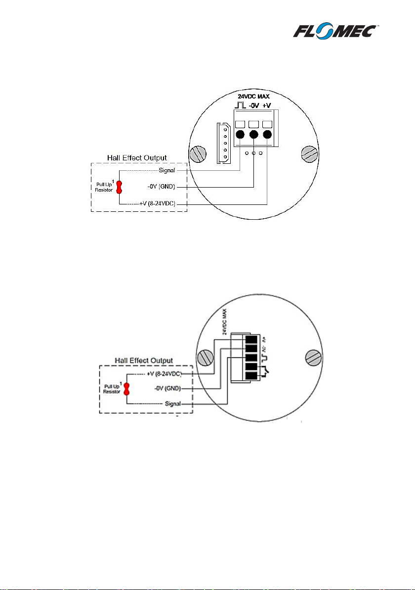
2.2.2 Hall Effect Outputs
The Hall Effect is a solid state 3 wire device which provides an open collector, NPN signal.
The output of the Hall Effect must be fitted with a pull-up resistor between the signal
output ( ) and the voltage supply. The Hall Effect output provides a square wave pulse
signal, which alternates between ground potential and the DC voltage available at the pull-
up resistor.
The NPN Hall Effect output is a reliable output type, producing a consistent output
irrespective of supply voltage variations, temperature variations, or mechanical shock. The
service life of the Hall Effect output is theoretically infinite, so long as it is protected from
high energy voltage spikes. Hall Effect outputs are protected against reverse polarity, and
against low energy voltage spikes; however, they are not protected against constant over-
voltage above the maximum limit of 24V (dc) (±5%).

12
Many secondary flow instruments are fitted with an integral pull-up resistor, but if
connecting the Hall Effect output to an electronic device that does not contain an integral
pull-up resistor, one MUST be fitted by the installer. The pull-up resistor is connected
between the signal terminal and the +VDC terminal; the recommended pull-up resistor
value is 10kΩ, 2.4kΩis the minimum value in a 24V (dc) system.
In low voltage systems using low pull-up resistor values, cases may occur where the
voltage level at the terminal will not be low enough to trigger the low-level logic on
receiving instruments. The equation below approximates the minimum pull-up resistor
value required based on the pull-up voltage level, and the low logic voltage threshold of the
instrument.
=
112
0.05 102
=Minimum value of pull-up resistor
=Voltage that signal is being pulled up to
=Low logic voltage threshold
Note: The hall effect sensor circuitry incorporates 2 x 51 ohm resistors in series with the
signal output.
2.2.3 Reed Switch Outputs
The reed switch output is a two wire normally-open SPST voltage free contact ideal for
installations without power, or for use as a simple apparatus in hazardous area locations.
When using the reed switch output the liquid temperature must not change at a rate
greater than 18°F (10°C) per minute, or the switch will be damaged. Reed switch reliability
and lifetime are very dependent on the voltage and current used; reducing system voltage
and switching current to a minimal value is recommended. Under ordinary conditions the
service life of the reed switch will exceed 2 billion actuations when switching less than 5V
(dc) and 10mA (as is the case when used with any of the available Integral Instruments)

13
2.2.4 Quadrature Pulse Outputs
The Quadrature Pulse (QP) output is an optional type of output that provides two
independent Hall Effect outputs that are electrically 90 degrees out of phase.When
installing a meter with Quadrature Pulse output it is important to remember that each
output terminal is independent, and as such each will require its own pull-up resistor as
described in Section 2.2.2 above.
2.3 Making Electrical Connections
To gain access to the electrical connections on a meter without an instrument, you must
first remove the terminal cover by removing the four cover screws with a 4mm Hex Key
(Allen Key). When removing the terminal cover, take care not to damage or lose the O-Ring.
Standard Pulse Output Boards utilise a pluggable terminal block which can be removed for
fitment of wires. Reed Only Pulse Output Boards use Cage Clamp terminal blocks which
require insertion of a screw driver into the wedging slot as show below. All wiring requires
a 0.1” (2.5mm) wide Flat Blade Screw Driver (or smaller).
For meters fitted with an integral instrument refer to the instruments instruction manual
that accompanied the meter.
When refitting a terminal cover for a Flameproof (EXd) flowmeter the terminal cover
screws must be tightened to a torque of 2.95ft-lb (4Nm). See section 2.7.3 for more
details.
Connecting wiring to Reed Only Pulse Output Boards

14
2.4 Wiring Diagrams
2.4.1 Standard Pulse Output Board
Applicable Models: 006, 008, 015, 025, 040, 050
Applicable Models: 004, 080, 080E, 100, 100E

15
Notes for Connection of standard Hall/Reed Pulse Output Boards
1. Pull up resistor required for operation of Hall Effect output; 10 kΩ is recommended. See
section 2.2.2 for further information.
2. For installations subject to electrical noise; signal filtering can be enabled on the Reed
Switch output by wiring the negative terminal of the reed switch (terminal 5) to the
GND terminal (terminal 2). When not using filtering on the Reed Switch output the
polarity of the wiring is not important.
3. Installing a current limiting resistor is recommended to extend the life of the Reed
Switch device; 800Ω is recommended as a minimum resistance value for a 24V system.
Resistor not required when connecting to battery powered flow instruments.

16
2.4.2 Reed Only Pulse Output Board
Applicable Models: 004,006,008
Applicable Models: 015,025,040, 050, 080, 080E, 100, 100E

17
Notes for Connection of Reed Only Pulse Output Boards
1. Reed Only pulse output boards are fitted with an on-board current limiting resistor
which will limit the total power into the circuit to less than 1W at 24V (dc) (when using
both outputs). This limitation provides perfect conditions for maximum Reed Switch
service life, and is required for use as a Simple Apparatus within a Hazardous Area.
When used in a Safe Area (non-hazardous) the current limiting resistor can be bypassed
by joining the solder link on the top surface of the PCB, however this will reduce Reed
Switch life. Please note that it is the responsibility of the user to ensure that total
power remains below 1W when used in a Hazardous Area.
2. The output resolution from each Reed Switch is as per the calibration sheet delivered
with the flowmeter; wiring the Reed Switch outputs in parallel will double the output
resolution (015 ~ 100 models only).
2.4.3 Reed Only Outputs as Simple Apparatus
When purchased with a ‘Reed Only” output the meter can be wired as an Intrinsically Safe
Simple Apparatus, see section 2.7.4 for further explanation of simple apparatus. The
wiring diagram below shows wiring of the Reed Switch signal from a meter located in the
hazardous area, to an MTL 5532 pulse isolator located in the safe area. The MTL pulse
isolator is shown as it is a common choice; however other brands and models of isolator
may be used in the same way provided they are designed for pulse or frequency signals.
Any barriers/isolators should only be installed after reading the manufacturer’s
instruction manual.
18
2.4.4 Hall Only Output
Applicable Models: 004 ~ 015 Hall Only, 004 & 006 High Resolution Option
Applicable Models: 025, 040, 050, 080, 080E, 100, 100E
Notes for Connection of Hall Only Pulse Output Boards
1. Pull up resistor required for operation of Hall Effect output; 10 kΩ is recommended. See
section 2.2.2 for further information.

19
2.4.5 Quadrature Pulse Output
Quadrature Pulse Outputs may be wired directly to any flow instruments that accept
quadrature signals for signal integrity verification (custody transfer applications) or for bi-
directional flow.
2.5 Meter Calibration Factor (K-Factor, Scale Factor)
Each flowmeter is individually calibrated and supplied with a calibration certificate
showing the number of pulses per unit volume (e.g. pulses/Litre) which is characteristic to
individual outputs on your meter. Meters fitted with integral instruments will have the
relevant K-factor entered into the program of the instrument at the factory.
2.6 Integral Instruments
If your flowmeter was purchased with an integral Rate Totaliser then the instrument will
be factory wired for reed switch input into the instrument. If your flowmeter is fitted with
an integral Batch Controller, the NPN (open collector) output from the Hall Sensor is factory
wired and programmed. If you are unsure of the factory wiring of your instrument, remove
the instrument bezel to check the wiring.
Unless programming details were provided at time of order, the instrument program will
contain factory default parameters. Integral instruments will be programmed with the
relevant K-factor for the meter, however all output(s) are turned OFF, and if required need
to be turned ON and then configured to suit the application requirements.
90° phase shift
between
Quadrature
Pulse
Output
Common +V (dc)
Common -0V
2
1
REED
V
QUAD
NPN HALL EFFECT

20
2.7 Installations in Hazardous Areas
Installations in Hazardous Areas are applications where the utmost care is necessary in
correctly selecting your flowmeter. If your flowmeter is to be used in a hazardous area it is
important that it has been correctly selected for the specific explosive atmosphere in which
it is to be used, and that installation be carried out by a competent person.
An Oval Gear flowmeter may be suitable for use in a hazardous area if it has been
purchased as Flameproof (EXd), Reed Only (Simple Apparatus), or with an integral certified
Intrinsically Safe instrument (EXi). Before installation ensure your meter is suitable for the
specific explosive gas or vapour present and the zone rating, gas group, and temperature
classification of your installation
For any installations measuring non-conductive liquids there may be a risk of electrostatic
build-up in the liquid. It is recommended that the guidance in IEC TS 60079-32-1 is followed.
2.7.1 ATEX/IECEx Flameproof Flowmeters (Ex db)
ATEX/IECEx flameproof (Ex db) Oval Gear flowmeters are designed and certified for use in
either Zone 1 or Zone 2 hazardous areas.
Flameproof flowmeters must be installed in accordance with hazardous area standards,
which require the use of certified cable glands, sealed conduit connections, and armoured
cable according to the international standards IEC/EN 60079:1 and IEC/EN 60079:14. The
extent of special wiring installation is dependent on the zone and gas group.
ATEX/IECEx flameproof flowmeters are available with either of the following equipment
ratings:
Group IIB – Aluminium or Stainless Steel meters suitable for hazardous gas atmospheres
in group IIB.
II 2 G
EX d IIB T6…T3 Gb
Group I/IIB – Stainless Steel meters suitable for mines subject to firedamp and gas
atmospheres in group IIB.
I M2 Ex d I Mb
II 2 G EX d IIB T6…T3 Gb
Table of contents
Other Flomec Measuring Instrument manuals

Flomec
Flomec OM025 User manual

Flomec
Flomec G Series User manual

Flomec
Flomec QS200 User manual

Flomec
Flomec TM Series User manual

Flomec
Flomec GPRO QM Series User manual

Flomec
Flomec QS200 User manual

Flomec
Flomec QS100-10 User manual

Flomec
Flomec TM Series User manual

Flomec
Flomec LM51DN User manual

Flomec
Flomec TM Series User manual

Flomec
Flomec EGM Series User manual

Flomec
Flomec QSE Series User manual

Flomec
Flomec QS200 User manual

Flomec
Flomec Q9 User manual

Flomec
Flomec QSE Series User manual

Flomec
Flomec G2 User manual

Flomec
Flomec D-40 User manual

Flomec
Flomec QS200 User manual

Flomec
Flomec 490 User manual

Flomec
Flomec Q9 User manual


