FLORABEST FSA 25 A1 User manual

®
IAN 311401
Wall-mounted Hose Box FSA 25 A1
Bedienungsanleitung
Wand - Schlauchbox
Bedienungs- und Sicherheitshinweise
Originalbetriebsanleitung
Gebruiksaanwijzing
Slangbox met wandbevestiging
Bedienings- en veiligheidsinstructies
Vertaling van de originele bedieningshandleiding
Wall-mounted Hose Box Instructions
Operation and Safety Notes
Translation of original operation manual
NL BE
DE AT CH
GB IE
FR BE
NI
Instructions relatives au enrouleur
de tuyau mural
Remarques concernant le fonctionnement et la sécurité
Traduction du manuel d'utilisation original

NI
NL / BE Vertaling van de originele bedieningshandleiding Pagina 25
GB/ IE/NI Translation of original operation manual Page 5
Voordat u gaat lezen, dient u de pagina met afbeeldingen open te vouwen en uzelf op de
hoogte te stellen van alle functies van het apparaat.
NL BE
Before reading, unfold the page containing the illustrations and familiarise yourself with all
functions of the device.
Klappen Sie vor dem Lesen die Seite mit den Abbildungen aus und machen Sie sich
anschließend mit allen Funktionen des Gerätes vertraut.
DE AT CH
Avant de lire, dépliez la page contenant les illustrations et familiarisez-vous avec toutes les
fonctions du dispositif.
FR BE
FR / BE Traduction du manuel d'utilisation original Page 45
DE/AT/CH Originalbetriebsanleitung Seite 69

C
12
11
10
9
8
7
654
3
2
1
1314
15
R 5° L 5°
5.7cm
16.5cm
100-110cm
4 – Φ10x50mm
D
®
IAN 297557
Wand - Schlauchbox FSA 25 A1
BedienungsanleitungWand - Schlauchbox
Bedienungs-und Sicherheitshinweise
Übersetzungder Original-Bedienungsanleitung
Wall-mountedHose Box Instructions
Operationand Safety Notes
Translationof original operation manual
DE AT CH

G
H I
F
E
10
88
1
2

5
GB IE NI
Content
Introduction ...................................................6
Intended use ......................................................6
General description .......................................7
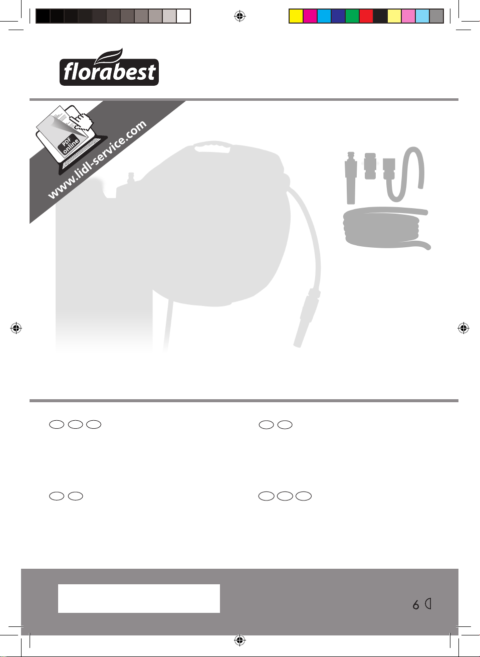
Package contents ........................................................7
Survey........................................................................7
Functional description ................................................7
Technical data ....................................................8
Safety instructions .............................................8
Symbols on the machine...............................................8
Symbols in the manual ................................................9
General safety instructions ............................................9
Assembly instructions ......................................10
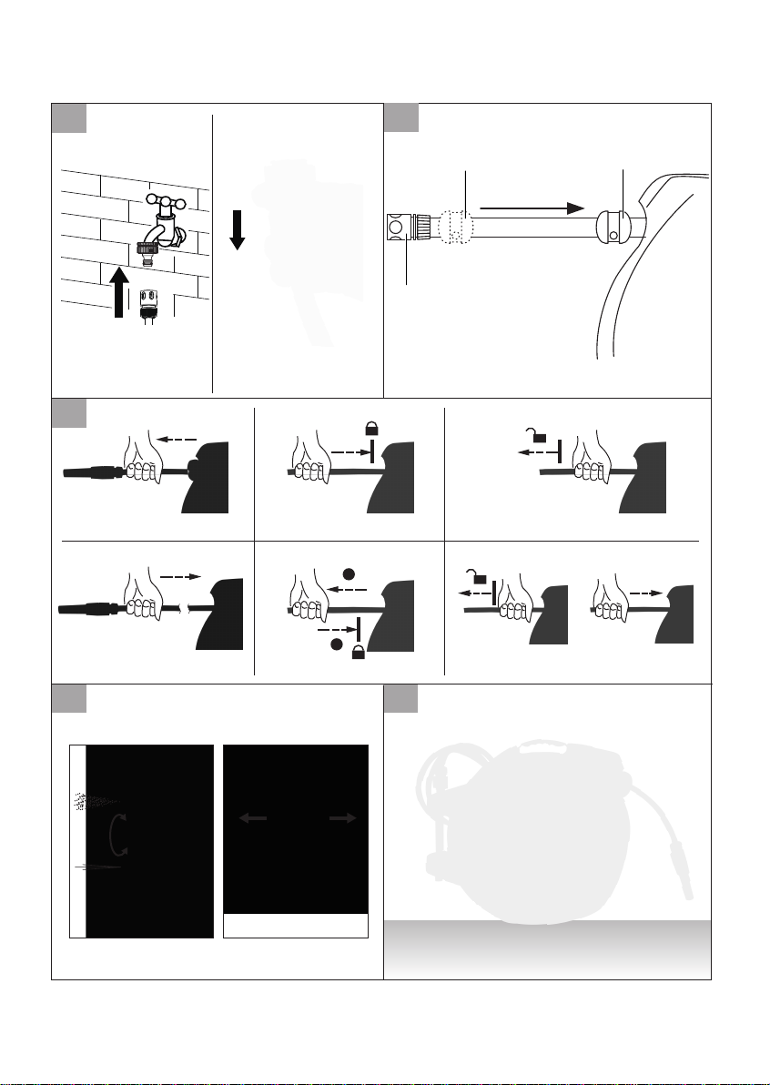
Mounting wall-mounted bracket ..................................10
Assembling hose box main body .................................11
Connecting /disconnecting the tap water.....................12
Shifting hose stopper..................................................12
Operation ......................................................12
Locking / unlocking outlet hose.................................12
Adjusting water jet...................................................13
Using wall-mounted hose box.......................................14
Cleaning and maintenance.............................16
Storage.......................................................17
Disposal and protection of the environment.......17
Trouble shooting.............................................18
Guarantee........................................................19
Repair Service.............................................22
Service-Center..........................................23
Translation of the original EC Declaration of
Conformity....................................................24

6
GB IE NI
can result in damage to the
hose box and give rise to
serious danger for the user.
The hose box must only be
used by adults. Young people
aged 16 and over may only
use the hose box under adult
supervision.
This equipment is not
suitable for commercial
use. Commercial use will
invalidate the guarantee.
The user or operator is
responsible for accidents
causing injury to other people
or damage to property.
The manufacturer cannot be
held liable for damage when
the hose box is not used in
conformity with its intended
purpose or due to incorrect
operation.
Introduction
Congratulations on the
purchase of your new device.
With it, you have chosen a
high quality product.
The operating instructions
constitute part of this product.
They contain important
information on safety, use
and disposal.
Before using the product,
familiarise yourself with all
of the operating and safety
instructions. Use the product
only as described and for the
applications specified.
Keep this manual safely and
in the event that the product
is passed on, hand over
all documents to the third
party.
Intended use
The wall-mounted hose box is
solely intended for watering
in the garden. Any other
use that is not specifically
approved in these instructions

7
GB IE NI
6. Faucet coupling
7. Hose guide (not shown)
8. Hose stopper
9. Outlet hose
10.Outlet hose male
coupling (with water
stopper)
11.Jet holder
12.Jet adjustment bar
13.Hose box main body
14.Main body carrying
handle
15.Cotter pin (not shown)
Functional description
The wall-mounted hose box
is equipped with the heavy
duty spring-loaded mechanism
to provide automatic slow
rewinding and lock hose
anywhere, and the guide
to prevent the hose from
overlapping, knot and tangle.
The wall-mounted bracket
allows the hose box to pivot
180°so the hose follows
your direction as you water.
Included 25m hose makes
General description
The illustration of the
principal functioning
parts can be found
on the front foldout
pages.
Package contents
Carefully unpack the wall-
mounted hose box and
check that it is complete.
Dispose of the packaging
material correctly.
●Wall-mounted hose box
●Mount bracket
●Mount hardware (4 sets
of screw, washer and
plastic plug)
●Instruction manual
Survey
1. Wall-mounted bracket
2. Bracket fixing screw
3. Hose box fixing
bar (with anti-drip
coupling)
4. Inlet hose
5. Inlet hose male
coupling
B

8
GB IE NI
Safety instructions
Make yourself familiar
with all the operating
instructions and safety
advice for the product
before installation.
If you pass the product
on to anyone else,
please ensure that you
also pass on all the
documentation with it.
Symbols on the
machine
Read the instruction
manual.
Do not direct the water
jet towards electrical
equipment!
Do not direct the water
jet towards persons or
animals!
Do not deliver drink
water.
watering easy and convenient
in your garden to save your
time.
When you are finished
watering, simply pull the hose
and the reel automatically
draws it back into the
weather-resistant plastic
housing. Unit easily removes
by pulling hose box fixing bar
(3) and disconnecting from
faucet for storage indoors in
winter season.
Technical data
Wall-mounted hose box ........
......................... FSA 25 A1
Rated working pressure........
..................................6 bar
Max. pressure...........10 bar
Hose length................25 m
Hose size....................1/2”
Working temperature .........
...................... 5 °C - 45 °C
Coupling ..................3 / 4"

9
GB IE NI
• Never leave children
unsupervised with the
packaging materials.
Danger of suffocation.
• Make sure that no water
pipes are damaged during
installation of the product.
Observe the operating
instructions for your safety.
• Ensure that all parts
are undamaged and
have been assembled
appropriately. Risk of
injury exists if assembled
incorrectly. Damaged
parts can effect safety and
function.
• Have the installation done
by experienced persons
only.
• Do not open the housing.
The springs are preset;
they may spring back.
• Never remove any screws
from parts of the housing.
• Never let the hose spring
back by itself. Guide it
carefully back into the
housing.
Symbols in the manual
Warning symbols
with information on
damage and injury
prevention.
Instruction symbols
(the instruction is
explained at the place
of the exclamation mark)
with information on
preventing damage.
Help symbols with
information on improving
tool handling.
General safety
instructions
Observe! When
using the machine,
please observe the
safety instructions.
• Keep the product out of the
hands of children.
• This product must not be
used by children.

10
GB IE NI
• Never let go of the hose if
the automatic stop function
is not engaged.
• Never allow the hose to
retract freely. This could
result in damage to the
product.
• Never block the hose end
with your fingers or other
objects during use.
• To avoid frost damage,
remove the hose reel from
the wall and store it dry
during winter.
• Ensure that the ground
near the hose reel is kept
as dry as possible.
• Turn the tap into the off
position when the hose
reel is not in use.
• The hose is not suitable for
delivering drinking water.
• Do not direct the water
jet towards electrical
equipment!
• Do not direct the water
jet towards persons or
animals!
Assembly instruction
Warning! The supplied
plastic plugs are suitable
for cement walls (plaster
up to 1cm).For other wall
types, special plugs must
be used.
The installation will use electric
power tools, read the safety
instruction completely before
operation. Have the installation
done by experienced persons
only.
Mounting wall-
mounted bracket
1. Mark 4 holes position
on the wall using the
wall mount bracket (1),
drill holes into the wall
50mm depth with an
Ø10mm percussion
drill. 100 - 110 cm
height of lower holes is
recommended.
Note: Higher than
110cm will possible
effect the auto rewind
function.
C

11
GB IE NI
2. Stick in the plastic
plugs to the end.
3. Screw and secure the
wall-mounted bracket
with the included
mount hardware (4
sets of screw, washer
and plastic plug) on
the wall. Make the
central line of bracket
as vertical as possible,
within 5°left/right
is recommended
to guarantee
180°smooth swivel.
4. Assemble the hose
box main body (See
“ Assembling hose
box main body” )
and check the pivot
rotation left / right.
Small adjustment of
bracket if necessary.
Assembling hose
box main body
1. Remove the cotter pin
(15) on the end of the
hose box fixing bar
(3).
2. Pull and remove the
hose box fixing bar (3)
from hose box, and
hold it.
3. Carry the main body
carrying handle (14)
and insert it into the
wall mount bracket (1).
4. Align the assembly
holes on hose box and
bracket, insert the hose
box fixing bar (3) to
secure the hose box
main body (13).
5. Swivel the hose box
main body (13) left
and right to check the
smoothness, make sure
the hose box main
body (13) can stay any
position.
6. Pull and return the
outlet hose to check the
function of automatic
slow rewinding, hose
locking and guiding.
7. Fix the cotter pin (15)
on the end of the hose
box fixing bar (3) .
D

12
GB IE NI
Connecting /
disconnecting the
tap water
1. Screw the faucet
coupling (6) to faucet.
2. Insert the inlet hose
male coupling (5) into
the faucet coupling (6)
with audible “click” to
secure
3. Pull back the sleeve
of inlet hose male
coupling (5) to
disconnect the water
connection.
Shifting hose
stopper
1. Loosen the 2 cross-
head screws on hose
stopper (8) with a
screwdriver
2. Hold the outlet hose (9)
securely and shift the
stopper (8) to desired
position, screw tightly
again with the 2 cross-
head screws.
Operation
Caution! Never
allow the hose
to retract freely.
This could result
in damage to the
product.
Never use the hose
box in the frost
period.
Locking / unlocking
outlet hose
During unwinding
1. Hold the outlet hose
(9) securely and pull
the outlet hose out to
desired length.
2. Stop pulling and allow
the outlet hose (9)
return slowly to lock. If
not, pull out the outlet
hose a short tug (10cm
at the beginning and
5cm at the end) again
and allow the outlet
hose (9) return to lock
3. Pull out the outlet hose
a short tug (10cm at
F
E
G

13
GB IE NI
the beginning and
5cm at the end) to
unlock.
Note: The lock and
unlock alternates on the
whole length, you can
repeat above actions to
engage lock and unlock
function alternatively.
During rolling up
1. Stop rolling up at
desired length and
pull out the outlet hose
a short tug (10cm at
the beginning and
5cm at the end).
2. Allow the outlet hose
(9) return slowly to
lock. If not, pull out
the outlet hose a short
tug (10cm at the
beginning and 5cm
at the end) again and
allow the outlet hose
(9) return to lock
3. Pull out the outlet hose
a short tug (10cm at
the beginning and
5cm at the end) to
unlock.
Note: The lock and
unlock alternates on the
whole length, you can
repeat above actions to
engage lock and unlock
function alternatively.
Adjusting water jet
Warning! Do not
direct the water
jet towards electric
equipment!
Do not direct the
water jet towards
persons or animals!
1.Use one hand to hold
the jet holder (11).
2.Use another hand
a)to turn the jet
adjustment bar (12)
clockwise to reduce
the water spray from
line to splash, to the
end to stop the water
spray.
b)to turn the jet
adjustment bar (12)
counter-clockwise to
enlarge the water
spray from splash to
H

14
GB IE NI
line, to the end to
the maximum water
spray.
Using wall-mounted
hose box
Caution! Never
allow the hose
to retract freely.
This could result
in damage to the
product.
Never use the hose
box in the frost
period.
Make sure the hose
box main body (13)
is securely fixed.
Always hold the
outlet hose (9)
securely to unwind
and roll up.
For tap water usage
only. Do not use
high pressure water.
Do not use with
chemicals of any
kind.
Warning!
Do not direct the
water jet towards
electric equipment!
Do not direct the
water jet towards
persons or animals!
Do not delver drink
water!
1. Turn the nozzle
adjustment bar (12)
clockwise to the end
to stop the water
spray.
2. Turn on the tap water.
3. Turn the hose box
main body (13) to
working direction,
hold the outlet hose
(9) securely and pull
the outlet hose out
to unwind to desired
length.
Note: There is a yellow
mark near the end of
the hose to show the
end. When the yellow
mark appears outside
A

15
GB IE NI
the opening, only 50 cm
of hose remain inside
the hose reel. Be careful
when extending the hose
further! Forcefully pulling
the hose when it reaches
the end can damage the
hose reel.
4. Lock the outlet hose (9)
and turn the nozzle
adjustment bar (12)
counter-clockwise to
start the water spray.
Always use one hand
to hold the nozzle
holder (11) when
watering.
5. Hold the outlet hose
(9) securely, unlock
the outlet hose (9) to
unwind or roll up it to
adjust the hose length.
It’s recommended
to turn the nozzle
adjustment bar (12)
clockwise to the end to
stop the water spray
before hose length
adjustment.
6. After watering, turn
the nozzle adjustment
bar (12) clockwise
to the end to stop the
water spray, hold
the outlet hose (9)
securely to roll up
slowly to the hose
stopper (8). If certain
length left outside
the hose box main
body (13), pull out
the outlet hose (9)
by 1-2m and roll up
again. Do not push
the hose back into the
hose box main body
(13).
Caution! Never allow
the hose to roll up freely.
This could result in
damage to the product.
Note: The built-in
automatic hose guide (7)
is preventing the hose
from overlapping while
rolling up. Do not use
hand to settle the hose
coil.

16
GB IE NI
There is a water stopper
inside the outlet hose
male coupling, help
change the nozzle with
the tap water on.
7. Turn off the tap water
and rotate the hose
box main body (13)
against the wall.
Cleaning and
maintenance
Any work that is not
described in these
Instructions must
be carried out by
a servicing agency
authorized by us.
1. Always keep the hose box
main body (13) clean. Do
not use cleaning agents
and solvents.
2. Always turn off the tap
water when the wall-
mounted hose box is not in
use
3. Use the water spray to
clean the hose box main
body (13). Do not immerse
the wall-mounted hose box
in water.
4. Remove the hose box
main body (13) indoors
in a frost period (See
“Storage”).
5. Check the inlet hose
(4) and outlet hose (9)
carefully. Do not use the
hose box if any cut on
them.
6. Check the seal O-ring on
nozzle holder (11) and
faucet coupling (6).
7. Contact our service center
if any problem.

17
GB IE NI
Storage
1. Carefully clean the
hose box main
body (13) and its
accessories.
2. Turn off the tap water
and remove the
inlet hose male
coupling (5) from the
faucet coupling (6).
3. Loop the inlet hose (4)
and insert the
inlet hose male
coupling (5) into the
anti-drip coupling (3).
4. Pull the cotter pin (15)
out of the Hose box
fixing bar (3)
5. Use one hand to grip
the main body
carrying handle (14)
and another hand to
pull out the hose box
fixing bar (3).
6. Remove the hose box
main body (13) from
wall-mounted bracket
(1) and insert the hose
box fixing bar (3)
back.
7. Replace the split pin
(15) in the fixing bolt
(3).
8. Carry the hose box
main body (13)
indoors for storage.
Disposal and
protection of the
environment
Dispose of the wall-mounted
hose box, its accessories
and the packaging in an
environment-friendly manner.
Hand in a redundant hose
box to a recycling center. The
plastic and metals can then
be sorted out and graded for
recycling. Our service center
will be happy to answer
any questions in this respect.
Defective units returned to us
will be disposed of for free.
I

18
GB IE NI
Trouble shooting
Problem Possible cause Remedy
Lock / unlock
defect different turn Repeat the action (See
“locking / unlocking
outlet hose”).
No water spray
tap water closed Turn on the faucet.
Water nozzle closed Turn the nozzle
adjustment bar (12)
counter-clockwise.
Kink or similar
blockage of rolled
up in the box hose.
Pull out the outlet hose
by 2m or more and
let hose roll up again.
Water leakage O-ring missing or
damaged Replace the O-ring.

19
GB IE NI
Guarantee
Dear Customer,
This equipment is provided
with a 3-year guarantee from
the date of purchase.
In case of defects, you have
statutory rights against the
seller of the product. These
statutory rights are not
restricted by our guarantee
presented below.
Terms of Guarantee
The term of the guarantee
begins on the date of
purchase. Please retain
the original receipt. This
document is required as proof
of purchase.
If a material or manufacturing
defect occurs within three
years of the date of purchase
of this product, we will repair
or replace – at our choice
– the product for you free
of charge. This guarantee
requires the defective
equipment and proof of
purchase to be presented
within the three-year period
with a brief written description
of what constitutes the defect
and when it occurred.
If the defect is covered by our
guarantee, you will receive
either the repaired product
or a new product. No new
guarantee period begins on
repair or replacement of the
product.
Guarantee Period and
Statutory
Claims for Defects
The guarantee period is not
extended by the guarantee
service. This also applies for
replaced or repaired parts.
Any damages and defects
already present at the time of
purchase must be reported
immediately after unpacking.
Repairs arising after expiry
of the guarantee period are
chargeable.
Guarantee Cover
The equipment has been
carefully produced in
accordance with strict quality
guidelines and conscientiously
checked prior to delivery.
The guarantee applies for all

20
GB IE NI
material and manufacturing
defects. This guarantee
does not extend to cover
product parts that are subject
to normal wear and may
therefore be considered as
wearing parts or to cover
damage to breakable parts
(e.g. switches, batteries).
This guarantee shall be
invalid if the product has been
damaged, used incorrectly or
not maintained. Precise
adherence to all of the
instructions specified in the
operating manual is required
for proper use of the product.
Intended uses and actions
against which the operating
manual advises or warns must
be categorically avoided.
The product is designed only
for private and not commercial
use. The guarantee will be
invalidated in case of misuse
or improper handling, use
of force, or interventions not
undertaken by our authorised
service branch.
Processing in Case of
Guarantee
To ensure quick handling of
you issue, please follow the
following directions:
• Please have the receipt and
item number
(e.g. IAN 311401) ready as
proof
of purchase for all enquiries.
• Please find the item number
on the rating plate, an
engraved plate on the
front page of your manual
(bottom left) or as a sticker
on the back or bottom.
• Should functional errors or
other defects occur, please
initially contact the service
department specified below
by
telephone or by e-mail.
You will then receive
further information on
the processing of your
complaint.
• After consultation with our
customer service, a product
recorded as defective
can be sent postage paid
to the service address
communicated to you,
This manual suits for next models
1
Table of contents
Languages:
Other FLORABEST Tools manuals
Popular Tools manuals by other brands

De Havilland
De Havilland DHC-3 OTTER Flight manual

Topex
Topex 07A210 Original instructions

US Conec
US Conec Loose Fiber Ribbonizing Tool Applications Engineering Notes

Kreg
Kreg KHI-PULL-INT owner's manual

molex
molex RHT-5770 Operating Instruction and Specifications Sheet

Rapid
Rapid PS101 operating instructions