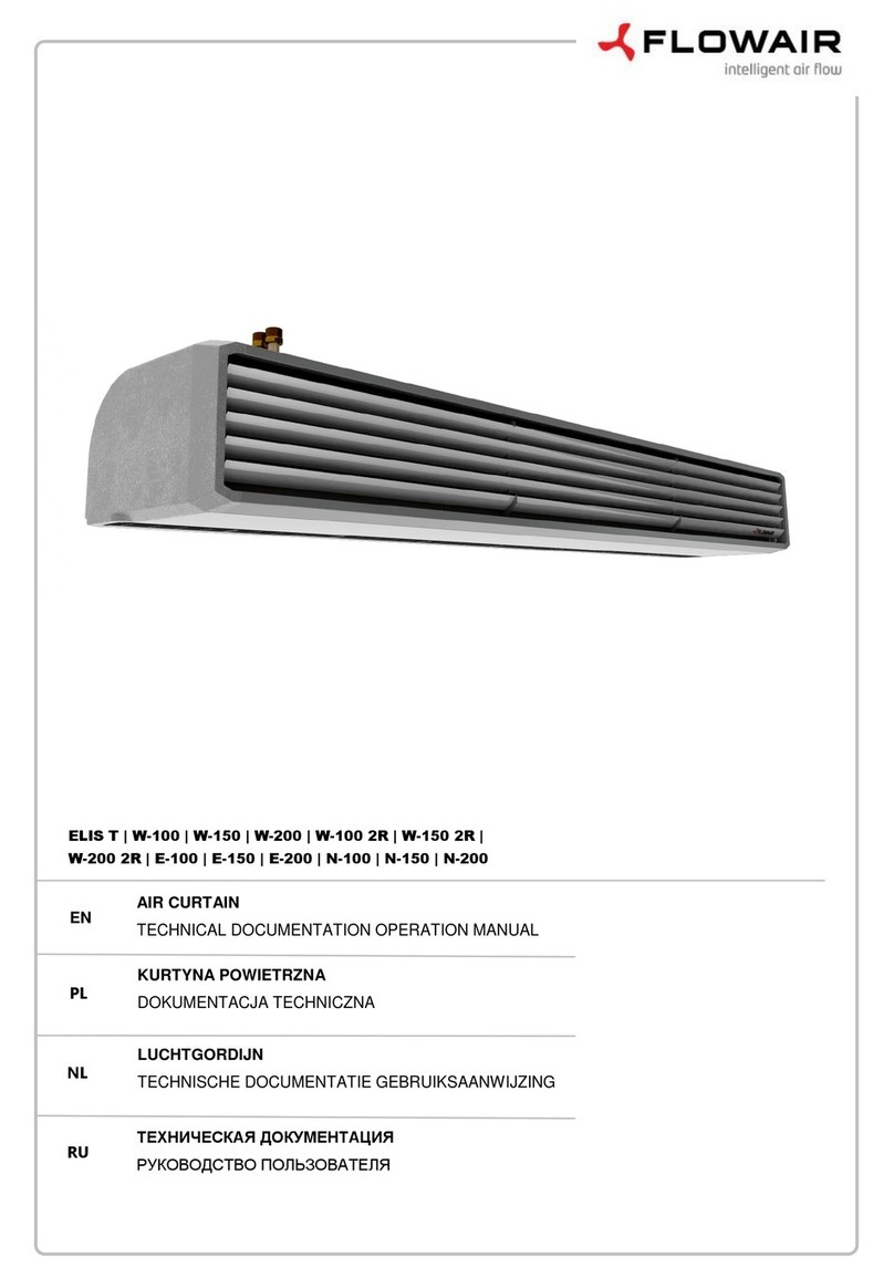
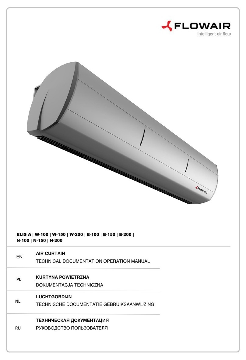
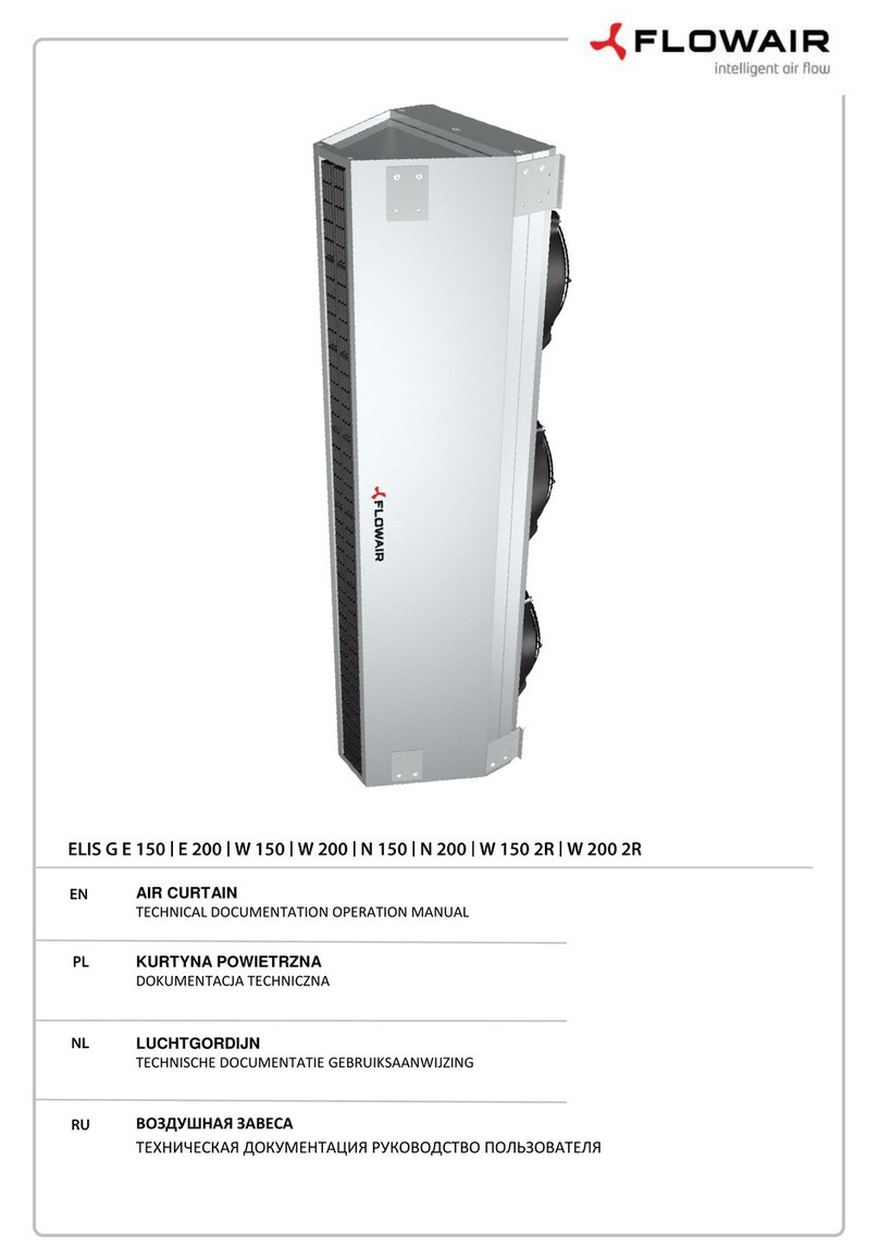
flowair Rooftop Cube User manual

www.flowair.com | 1
Rooftop Cube
SHORT ASSEMBLY INSTRUCTION
v1.1 EN

2 |www.flowair.com
01.2022r

www.flowair.com | 3
This manual was published by FLOWAIR Głogowski and Brzeziński Sp. J. User’s and installation manual is a set of recommendations
and tips designed to show procedures, methods and remarks for proper installation, launch of the unit.
The manufacturer reserves the right to correct and change the user’s manual anytime without notice, so as changes in
the devices not influencing its operation.
Before installation, launch of Cube device, the customer should read thoroughly this manual. All guidelines mentioned in the
manual should be applied without omitting any point. Failure to adhere to the following points may result in life-threating due to
improper transport and installation and can lead to damages to the unit or its improper operation. The manufacturer shall not be
liable for deficiencies during installation and unit improper operation due to failure to comply with this manual. Meanwhile, the
producer’s warranty will not be applied in case of gross negligence or not complying with this manual.
You should consult the service or manufacturer if this manual contains incomprehensible or ambiguous descriptions.
All activities during connecting to electrical installation must be conducted by qualified staff, having necessary
attestations and certificates to work with voltage devices according to the laws of the country.
This manual is only intended to use for persons installing the Cube devices. Its content is legally protected and must not be copied,
translated or processed (including electronic media) in total or partially without the manufacturer’s written declaration of consent.
FLOWAIR Głogowski i Brzeziński Sp.J.
Office:
ul. Chwaszczyńska 135, 81-571 Gdynia
tel. +48 (58) 627 57 41, fax +48 (58) 627 57 21

4 |www.flowair.com
TABLE OF CONTENTS
1. TRANSPORT.................................................................................................................................................................................................................... 5
1.1. Horizontal transport .............................................................................................................................................................................................. 5
1.2. Transport dimensions Cube 20 .......................................................................................................................................................................... 5
1.3. Transport dimensions Cube 40 .......................................................................................................................................................................... 6
1.4. Transport dimensions Cube 50/60.................................................................................................................................................................... 6
1.5. Transport dimensions Cube 80/100 ................................................................................................................................................................. 6
1.6. Transport dimensions Cube 80/100 L ............................................................................................................................................................. 7
1.7. Transport dimensions Cube 120/160 B ........................................................................................................................................................... 7
1.8. Transport dimensions Cube 120/160 R ........................................................................................................................................................... 7
1.9. Transport dimensions Cube R8.......................................................................................................................................................................... 8
1.10. Transport dimensions NWS module (Cube 20/R8 NWS) ...................................................................................................................... 8
1.11. Transport dimensions NWL module (Cube 40 NWL) ............................................................................................................................. 8
1.12. Lifting information ........................................................................................................................................................................................... 9
1.13. Lifting Cube 20 ................................................................................................................................................................................................ 10
1.14. Lifting Cube 40 ................................................................................................................................................................................................ 11
1.15. Lifting Cube 50/60.......................................................................................................................................................................................... 12
1.16. Lifting Cube 80/100........................................................................................................................................................................................ 13
1.17. Lifting Cube 120/160 ..................................................................................................................................................................................... 14
1.18. Lifting heat recovery module...................................................................................................................................................................... 15
1.19. Lifting Cube R8 ................................................................................................................................................................................................ 16
1.20. Rotating the module NWS/NWL ................................................................................................................................................................ 17
1.21. Lifting NWS module (Cube 20/R8)............................................................................................................................................................. 19
1.22. Lifting NWL module(Cube 40 NWL) .......................................................................................................................................................... 20
2. FOUNDATION .............................................................................................................................................................................................................. 21
2.1. Foundation Cube unit......................................................................................................................................................................................... 21
2.2. Roof crosing NWS (Cube 20/R8 NWS) ............................................................................................................................................................ 27
2.3. NWS instalation (Cube 20/R8 NWS) ................................................................................................................................................................ 28
2.4. Roof crossing NWL (Cube 40 NWL) ................................................................................................................................................................. 31
2.5. NWL installation (Cube 40 NWL)...................................................................................................................................................................... 32
2.6. Inlet and exhaust covers installation (not applicable to the Cube 40 unit)........................................................................................34
2.7. Heat recovery unit installation Cube 80/100 L i Cube 120/160 R .......................................................................................................... 35
3. INSTALLATION............................................................................................................................................................................................................. 37
3.1. Hydraulic connection - units for duct installation...................................................................................................................................... 37
3.2. Hydraulic hub chart for water heater in the rooftop unit ........................................................................................................................ 38
3.3. Hydraulic connection – units dor ductless installation............................................................................................................................. 39
3.4. Hydraulic hub chart for water heater in the NW module......................................................................................................................... 40
3.5. Condensation drain ............................................................................................................................................................................................. 41
3.6. Electric connection............................................................................................................................................................................................... 43
3.7. Installation flow chart.......................................................................................................................................................................................... 52
4. START-UP AND EXPLOITATION .............................................................................................................................................................................. 54
4.1. Electric heater........................................................................................................................................................................................................ 54
4.2. Gas heater ............................................................................................................................................................................................................... 54
4.3. Water heat exchanger......................................................................................................................................................................................... 55
4.4. Water cooler........................................................................................................................................................................................................... 55
4.5. Rotational exchanger .......................................................................................................................................................................................... 55
4.6. Fans........................................................................................................................................................................................................................... 55
4.7. Dampers.................................................................................................................................................................................................................. 55
4.8. Automation control systems............................................................................................................................................................................. 55
4.9. Filter replacment................................................................................................................................................................................................... 56
5. RESPONSIBILITY TABLE............................................................................................................................................................................................. 58

www.flowair.com | 5
1. TRANSPORT
An integrated frame with handles for forklift or integrated handles to lift unit on ropes is used for transport the Cube units.
Please follow below regulations during transport:
•Before unloading the transport, complete the handover protocol.
•Please check parcel completion and unit state immediately after delivery (duct temperaturę sensor – not applicable
unit with NW supply module, T-box - option, ventilation covers – not applicable Cube 40, room temperature sensor -
option). In case of any irregularities a damage protocol should be written down. This can help claiming indemnities
from shipping company later.
•Unloading should be done with forklift (using frame handles or palette where unit is mounted) or a lift (using handles
on unit’s casing).
•During transport or storage, the unit must stand on integrated frame. Leaving unit in different way may lead to its
damage.
•After unloading, during waiting for installation, a cover protecting from external factors must be used.
The manufacturer is not responsible for damages caused by not following the guidelines written in the manual or for
transport irregularities.
1.1. Horizontal transport
Cube units are prepared for transport using forklift; equipped with transport rails gives the opportunity for loading or unloading
without additional support or transport equipment.
Because of unit’s weight and front-end center of gravity, the size of the forklift and length of truck forks must be
adapted to unit’s dimension. Pay special attention to the length of truck forks, which should have at least ¾ depth of
transport rail. Shorter truck forks application may result in damage to the unit or accident what the manufacturer is not
responsible for.
Before installing the device, remove the transport rails by unscrewing the screws.
1.2. Transport dimensions Cube 20
•
W (Cube / + blocks / + space) - 1492 / 1592 / 1692 mm
•S(Cube / + styro / + space) - 1380 / 1480 / 1580 mm
•D (Cube / + styro / + space) - 2300 / 2400/ 2500 mm
•Ventilation duct covers – 473 mm (transport inside)
•Length of the forks – min. 1500 mm
•Fork spacing – min. 350 mm
•Weight – up to 850 kg

6 |www.flowair.com
1.3. Transport dimensions Cube 40
•W (Cube / + space) - 1742 / 1842 mm
•S (Cube / + styro / + space) - 2200 / 2300 / 2400 mm
•D (Cube / + styro / + space) - 2300 / 2400 / 2500 mm
•Ventilation duct covers – not applicable
•Length of the forks – min. 2300 mm
•Fork spacing – min. 485 mm
•Weight – up to 1100 kg
1.4. Transport dimensions Cube 50/60
•W (Cube / + space) - 1790 / 1890 mm
•S (Cube / + styro / + space) - 3100 / 3200 / 3300 mm
•D (Cube / + styro / + space) - 2300 / 2400 / 2500 mm
•Ventilation duct covers – 482 mm (transport inside)
•Length of the forks – min. 2400 mm
•Fork spacing – min. 845 mm
•Weight –Cube 50 – up to 1600 kg,
Cube 60 – up to 1650 kg
1.5. Transport dimensions Cube 80/100
•W (Cube / + space) - 2310 / 2410 mm
•S (Cube / + styro / + space) - 3100 / 3200 / 3300 mm
•D (Cube / + styro / + space) - 2300 / 2400 / 2500 mm
•Ventilation duct covers – 482 mm (transport inside)
•Length of the forks – min. 2400 mm
•Fork spacing – min. 845 mm
•Weight – Cube 80 - up to 1990 kg,
Cube 100 – up to 2250 kg

www.flowair.com | 7
1.6. Transport dimensions Cube 80/100 L
•
W (Cube / + space) - 2310 / 2410 mm
•S (Cube / + styro / + space) - 3100 / 3200 / 3300 mm
•D (Cube / + styro / + space) - 2300 / 2400 / 2500 mm
•Ventilation duct covers – 482 mm (transport inside)
•Length of the forks – min. 2400 mm
•Fork spacing – min. 845 mm
•Weight – Cube 80 -up to 1990 kg,
Cube 100 – up to 2250 kg
•
W (L module / + space) - 2310 / 2410 mm
•S (L module / + styro / + space) - 573 / 673 / 773 mm
•D (L module / + styro / + space) - 2300 / 2400 / 2500 mm
•Length of the forks – min. 2400 mm
•Fork spacing – min. 350 mm
•Weight - 350 kg
1.7. Transport dimensions Cube 120/160 B
•W (Cube / + space) - 2310 / 2410 mm
•S (Cube / + styro / + space) - 2300 / 2400 / 2500 mm
•D (Cube / + styro / + space) - 4200 / 4300 / 4400 mm
•Ventilation duct covers – 482 mm (transport inside)
•Length of the forks – min. 2400 mm
•Fork spacing – min. 845 mm
•Weight – Cube 120 – up to 2250 kg,
Cube 160 – up to 2350 kg
1.8. Transport dimensions Cube 120/160 R
•W (Cube / + space) - 2310 / 2410 mm
•S (Cube / + styro / + space) - 2300 / 2400 / 2500 mm
•D (Cube / + styro / + space) - 4200 / 4300 / 4400 mm
•Ventilation duct covers – 482 mm (transport inside)
•Length of the forks – min. 2400 mm
•Fork spacing– min. 845 mm
•Weight – Cube 120 – up to 2250 kg,
Cube 160 – up to 2350 kg
•W (L module/ + space) - 2310 / 2410 mm
•S (L module/ + styro / + space) - 573 / 673 / 773 mm
•D (L module / + styro / + space) - 2300 / 2400 / 2500 mm
•Length of the forks – min. 2400 mm
•Fork spacing – min. 350 mm
•Weight - 350 kg

8 |www.flowair.com
1.9. Transport dimensions Cube R8
•W (Cube / + blocks / + space) - 1492 / 1592 / 1692 mm
•S (Cube / + styro / + space) - 1380 / 1480 / 1580 mm
•D (Cube / + styro / + space)- 2300 / 2400 / 2500 mm
•Ventilation duct covers – 473 mm (transport inside)
•Length of the forks – min. 1500 mm
•Fork spacing – min. 350 mm
•Weight – do 800 kg
1.10. Transport dimensions NWS module (Cube 20/R8 NWS)
•
W (NW / + palette / + space) - 2584 / 2684 / 2784 mm
•S (NW / + styro / + space) - 1380 / 1480 / 1580 mm
•D (NW / + styro / + space) - 2300 / 2400/ 2500 mm
•Length of the forks – min. 1500 mm
•Fork spacing – min. 350 mm
•Weight – up to 250 kg
1.11. Transport dimensions NWL module (Cube 40 NWL)
•W (NW / + palette / + space) - 2584 / 2684 / 2784 mm
•S (NW / + styro / + space) - 2300 / 2400/ 2500 mm
•D (NW / + styro / + space) - 2300 / 2400/ 2500 mm
•Length of the forks – min. 1500 mm
•Fork spacing – min. 350 mm
•Weight –up to 250 kg

www.flowair.com | 9
1.12. Lifting information
When lifting the Cube and the heat recovery module, follow these rules:
•Make sure that the ropes are properly attached to all holders,
•Always kift the device and the heat recovery module separately,
•Make sure that the device is level during lifting,
•Be especially careful when removing from the truck, so as not to damage the device by hitting the trailer elements,
•Be careful not to hit the device with any other objects,
•Do not lift the device at excessive speed,
•Do not change direction abruptly,
•Be especially careful when setting the device on a structural frame or a roof base.
Do not stand under the device during lifting.
•The manufacturer is not responsible for damages caused by not following the guidelines written in the manual or for
transport irregularities.
•Before lifting, check that the locks on all service panels are closed and verify by pulling the handles.

10 |www.flowair.com
1.13. Lifting Cube 20
All Cube units are equipped with handles for ropes, localized in upper part, allowing to lift the unit. Spreader beam application is
not necessary. Handles for lifting the unit and heat module are indicated in pictures below.
Because of load distribution, minimum length of hoisting ropes from handle to hook is 3,5 m. Disobeying this
recommendation may result in damage to unit or even mounting breach.

www.flowair.com | 11
1.14. Lifting Cube 40
All Cube units are equipped with handles for ropes, localized in upper part, allowing to lift the unit. Spreader beam application is
not necessary. Handles for lifting the unit and heat module are indicated in pictures below.
Because of load distribution, minimum length of hoisting ropes from handle to hook is 3,5 m. Disobeying this
recommendation may result in damage to unit or even mounting breach.

12 |www.flowair.com
1.15. Lifting Cube 50/60
All Cube units are equipped with handles for ropes, localized in upper part, allowing to lift the unit. Spreader beam application is
not necessary. Handles for lifting the unit and heat module are indicated in pictures below.
Because of load distribution, minimum length of hoisting ropes from handle to hook is 3,5 m. Disobeying this
recommendation may result in damage to unit or even mounting breach.

www.flowair.com | 13
1.16. Lifting Cube 80/100
All Cube units are equipped with handles for ropes, localized in upper part, allowing to lift the unit. Spreader beam application is
not necessary. Handles for lifting the unit and heat module are indicated in pictures below.
•Because of load distribution, minimum length of hoisting ropes from handle to hook is 3,5 m. Disobeying this
recommendation may result in damage to unit or even mounting breach.
•The Cube 80/100 L cannot be raised with the heat recovery module attached. Installation of the heat recovery module
to the Cube 80/100 L device should be done on the roof, after mounting the Cube device. Installation is carried out in
accordance with the guidelines presented later in this manual.

14 |www.flowair.com
1.17. Lifting Cube 120/160
All Cube units are equipped with handles for ropes, localized in upper part, allowing to lift the unit. Spreader beam application is
not necessary. Handles for lifting the unit and heat module are indicated in pictures below. To attach the ropes to the integrated
mounting brackets for devices using, 4 standard shackles with a culvert with a 16 mm diameter shank should be taken.
•Because of load distribution, minimum length of hoisting ropes from handle to hook is 3,5 m. Disobeying this
recommendation may result in damage to unit or even mounting breach.
•The Cube 120/160 R cannot be raised with the heat recovery module attached. Installation of the heat recovery module

www.flowair.com | 15
1.18. Lifting heat recovery module
Due to the size, the module containing the heat recovery exchanger must be transported disconnected from the device. The
module is equipped with lifting eyes with ropes located in the upper part of the housing. No shackles are required to lift the heat
recovery module.
The Cube 80/100 and Cube 120/160 R units cannot be raised with the heat recovery module attached.

16 |www.flowair.com
1.19. Lifting Cube R8
All Cube units are equipped with handles for ropes, localized in upper part, allowing to lift the unit. Spreader beam application is
not necessary. Handles for lifting the unit and heat module are indicated in pictures below.
Because of load distribution, minimum length of hoisting ropes from handle to hook is 3,5 m. Disobeying this
recommendation may result in damage to unit or even mounting breach.

www.flowair.com | 17
1.20. Rotating the module NWS/NWL
The supply air module is delivered to the site of delivery upside down. Before placing the module on the base, be careful when
turning it in the corect position as to not demage the module.
In order the secure module when turning it please use the styrofoam cover which comes with the module.
Place the air supply module carefully in horizontal position, then attach the ropes to the prepared lugs and start lifting it carefully
usinig steroform cover as a protective base a spacially seciuring the corners.
The polystyrene cover should not be removed before turning over NW supply module. Storing the device without the
polystyrene cover may damage the actuator.

18 |www.flowair.com
In order the secure module when turning it please use the styrofoam cover which comes with the module.
The polystyrene cover should not be removed before turning over NW supply module. Storing the device without the
polystyrene cover may damage the actuator.

www.flowair.com | 19
1.21. Lifting NWS module (Cube 20/R8)
All Cube units are equipped with handles for ropes, localized in upper part, allowing to lift the unit. Spreader beam application is
not necessary. Handles for lifting the unit and heat module are indicated in pictures below.
The NWL supply module is delivered to the place of delivery upside down. To position the device, carefully rotate
the supply air module so as not to damage the casing. Use the polystyrene cover to protect the NWS supply
module while turning. The process of rotating the module is described in section 5.20.
•The polystyrene cover should not be removed before turning over NWS supply module. Storing the air supply module
without a polystyrene cover may damage the actuator.
•Because of load distribution, minimum length of hoisting ropes from handle to hook is 3,5 m. Disobeying this
Before placing the device on the NWS supply air module, unscrew the transport lugs.

20 |www.flowair.com
1.22. Lifting NWL module(Cube 40 NWL)
All Cube units are equipped with handles for ropes, localized in upper part, allowing to lift the unit. Spreader beam application is
not necessary. Handles for lifting the unit and heat module are indicated in pictures below.
The NWL supply module is delivered to the place of delivery upside down. To position the device, carefully rotate
the supply air module so as not to damage the casing. Use the polystyrene cover to protect the NWS supply
module while turning. The process of rotating the module is described in section 5.20.
•The polystyrene cover should not be removed before turning over NWL supply module. Storing the air supply module
without a polystyrene cover may damage the actuator.
•Because of load distribution, minimum length of hoisting ropes from handle to hook is 3,5 m. Disobeying this
Before placing the device on the NWL supply air module, unscrew the transport lugs.
Table of contents
Other flowair Fan manuals

flowair
flowair mini. E-90 Guide

flowair
flowair Uvo User manual

flowair
flowair UVO H EC Series Guide

flowair
flowair OXeN User manual

flowair
flowair OXeN X2-W-1.2-V User manual

flowair
flowair ELIS T-W-100 Guide

flowair
flowair LEO D 2 Guide

flowair
flowair LEO D S Guide

flowair
flowair OXeN X2-W-1.2-V Guide

flowair
flowair ELIS B-W-100 Guide