FlowLine EchoPro LR36 Series User manual

Flowline, Inc. | 10500 Humbolt Street, Los Alamitos, CA 90720 p 562.598.3015 f 562.431.8507 w flowline.com QS301905 Rev A
EchoPro®
Radar Liquid & Solid Level Transmitter
LR36, LR41 & LR46 Series Quick Start
©2017 Flowline, Inc.
All Rights Reserved
Made in USA

| 2 QS301905 Rev A
WELCOME TO THE ECHOPRO® QUICK START
The EchoPro® Quick Start Guide is meant to show the basic configuration settings to get the EchoPro® up
and running quickly. If you run into an issue that is not addressed here or wish to install or set up with a non-
standard configuration, please address the EchoPro® Manual or refer to the Flowline website at
www.flowline.com.
WE DO YOUR LEVEL BEST
Thank you for purchasing EchoPro®. The sensor provides level measurement for your tank application. This
Quick Start includes everything you’ll need to get the sensor up and running.
SENSOR MODELS
Offered in three different models, EchoPro® is an intrinsically safe, two-wire, pulse radar level sensor that
provides a continuous 4-20 mA current output that’s proportional to the media level in a tank or sump. Make
sure that the model purchased is appropriate for your application.
SOLIDS LEVEL TRANSMITTERS
Series Max
Range Beam Angle Material Mounting FCC
Compliance Application
LR36 49.2’
(15m)
12° (3” horn)
316L SS
1-1/2” NPT
4” or 5” flanged
gimbal
Part 15.256,
Class B
Solids with normal
temperature and normal
pressure under 32.8’
(10m)
8° (4” horn)
6° (5” horn)
LR41 229.7’
(70m)
12° (3” horn)
316L SS
1-1/2” NPT
4” or 5” flanged
gimbal
Part 15.256,
Class B
Solids with dew / dust /
crystal under 98.4’ (30m)
8° (4” horn)
6° (5” horn)
LR46 229.7’
(70m)
5° (8” parabolic)
316L SS
1-1/2” NPT
4” or 5” flanged
gimbal
4”, 5”, 6”, 8” or
10” flange
Part 15.256,
Class B
Solids with strong dew /
dust / crystal or ranges
over 98.4’ (30m)
4° (10” parabolic)

QS301905 Rev A 3 |
FCC CONFORMITY
This instrument complies with Part 15 of the FCC Rules. Operation is subject to the following two
conditions: (1) this instrument may not cause harmful interference, and; (2) this instrument must accept any
interference received, including interference that may cause undesired operation.
Changes or modifications not expressly approved by the manufacturer could void the user’s authority to
operate the equipment.
Warning: User must keep a safety distance of at least 20cm from the antenna.
NOTE: LR36 (4” & 5” horn), LR41 (4” & 5” horn) & LR46 (8” and 10” parabolic) series: This
equipment has been tested and found to comply with the limits for a Class B digital device, pursuant to Part
15 of the FCC Rules. These limits are designed to provide reasonable protection against harmful
interference in a residential installation. This equipment generates uses and can radiate radio frequency
energy and, if not installed and used in accordance with the instructions, may cause harmful interference to
radio communications. However, there is no guarantee that interference to radio and television reception,
which can be determined by turning the equipment off and on, the user is encouraged to try to correct the
interference by one or more of the following measures:
Reorient or relocate the receiving antenna.
Increase the separation between the equipment and the receiver.
Isolate the equipment to an outlet different from where the receiver is connected.
Consult the dealer or an experienced technician for help.

| 4 QS301905 Rev A
USING THE DISPLAY
The display module features a dot matrix LCD display with 4 push buttons on a
removable puck. Out of the box, the display indicates level in feet and depicts
the level within the 4-20mA span on a bar graph at the right side of the display.
The four buttons perform the following functions:
ESCAPE
o Exit configuration mode
o Return to a higher menu level
o Display Echo Curve
Up Arrow
o Modify parameter values
o Choose display mode
Right Arrow
o Choose configuration options
o Choose parameter digits to edit
o Display contents of parameters
ENTER
o Enter Menu and Options
o Confirm configuration options
o Confirm changes to parameters
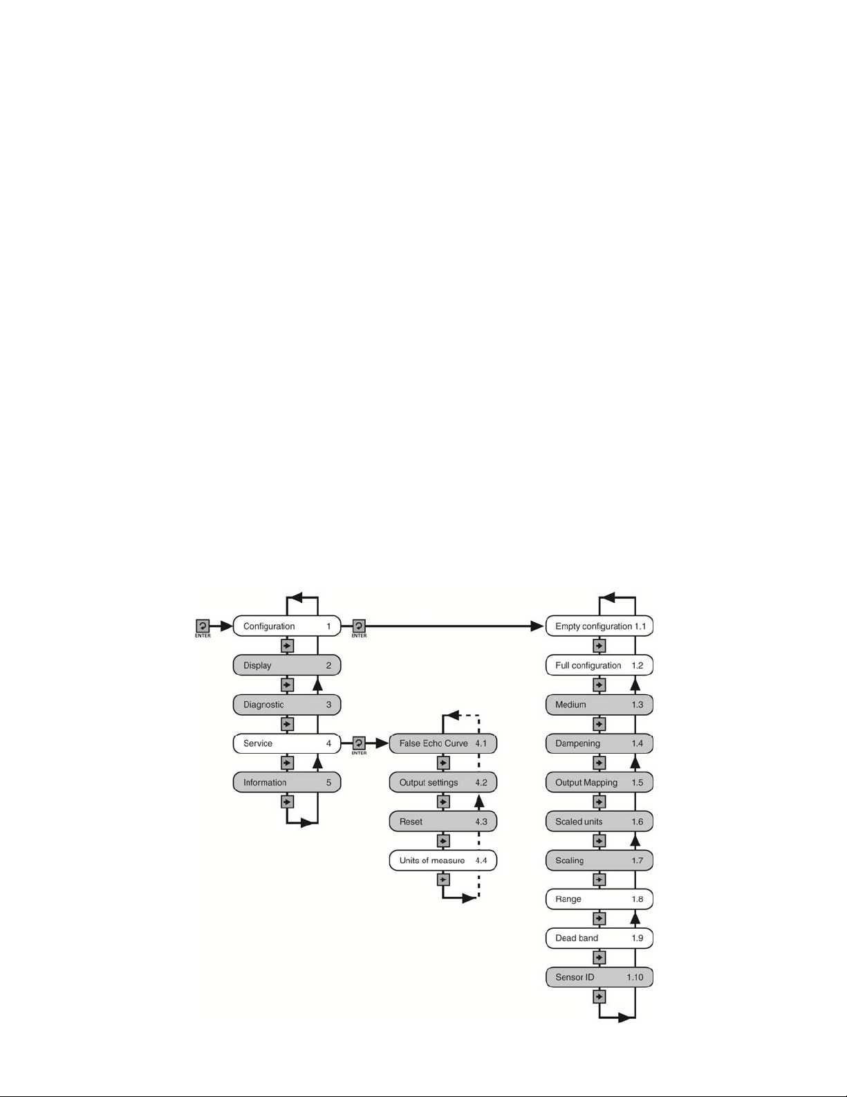
MENU INTRODUCTION
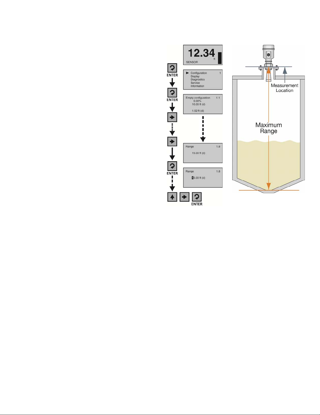
1) To enter the Main Menu (from the Main Screen), press the ENTER button.
2) Use the Right Arrow button to scroll through the Main Menu options.
a) Configuration - Below are the configuration menu functions:
i) Empty Configuration
ii) Full Configuration
iii) Medium
iv) Dampening
v) Output Mapping
vi) Scaled Units
vii) Scaling
viii) Range
ix) Dead Band
x) Sensor ID
b) Display - This menu function sets the display mode and contrast.
c) Diagnostics - Below are the diagnostic menu functions:
i) Measurement of Peak Values
ii) Measurement Status
iii) Echo Curve
iv) Simulation
d) Service - Within the service menu functions, you can store a False
Echo Curve, set units of measurement, change output settings, reset
configuration settings, set language or set a PIN for the sensor.
e) Info - This item provides information on the sensor’s type, serial
number, date of manufacture and software version.
3) To select one of the functions, press ENTER.
4) To exit the programming mode, press ESC.

QS301905 Rev A 5 |
BASIC CONFIGURATION OVERVIEW
Below are the 9 basic steps to configure the sensor for operation. Each step is described in detail on the
following pages
1) Measure the Tank
a) Begin by measuring the key tank and fitting dimensions. Correct tank dimensions will result in accurate
sensor measurement.
2) Set the Units of Measurement
a) Units can be configured in basic engineering units of length including Feet or Meters.
3) Set the Empty Configuration
a) This is the empty setting (4mA) for the tank.
4) Set the Full Configuration
a) This is the full setting (20mA) for the tank.
5) Set the Range (Maximum Range or MaxR)
a) This is the maximum measurement range for the sensor. The sensor will ignore all echo returns
beyond this setting.
6) Set the Dead Band (Minimum Range or MinR)
a) This is the minimum measurement range for the sensor. The sensor will ignore all echo returns closer
than this setting.
7) Check the Echo Curve
a) This is a quick diagnostic tool to determine if the sensor is reading the correct level.
8) Install the Sensor
a) Review the installation requirements to assist in the mounting of the sensor.
9) Wire the Sensor

| 6 QS301905 Rev A
STEP 1 – MEASURE THE TANK
Measuring the tank is one of the most important aspects
in configuring the sensor. When measuring the tank,
take into account the location of the sensor with respect
to fittings, risers, dome tops and bottoms, and identify
where the measurements are taken from the sensor.
Note: The location for measurement may be different
among different sensor Series, based upon the type of
antenna. Refer to the Measurement Reference Chart for
the measurement location of your sensor. The basic
measurements for configuration are described below:
1) Distance from the sensor’s measurement location to
the bottom of the tank is the Max. Range value. The
Range value is typically set at the bottom of the tank.
2) Distance from the sensor’s measurement location to
the empty or lowest liquid level in the tank is the
Sensor Height.
a) Sensor Height = 4mA setting.
b) With flat bottom tanks, the Range and Sensor
Height values can be the same.
3) Distance from the sensor’s measurement location to
the full or highest liquid level in the tank is the Fill-
Height.
a) Fill-Height = 20mA setting.
Measurement Reference Chart
LR36 & LR41 Series LR46 Series

QS301905 Rev A 7 |
STEP 2 – SET THE UNITS OF MEASUREMENT
This function sets the units for all measurement values to be entered into the sensor. The choices for units are
feet and meters. The unit is shipped with a default setting of feet.
1. From the Main Screen, press Enter to advance
into the Main Menu.
2. Press Right Arrow repeatedly until the arrow is
next to Service.
3. Press Enter to advance into the Service menu
(Echo curve will appear).
4. Press Right Arrow repeatedly until the menu
shows Units of Measurement.
5. Press Enter to advance into Units of
Measurement.
6. Press Right Arrow to change the setting
between feet [ft (d)] and meters [m (d)].
7. When the units are correct, press Enter to save the setting.
8. When done, press ESC to return to the Main Menu, and press ESC a
second time to return to the Main Screen.

| 8 QS301905 Rev A
STEP 3 – SET THE SENSOR HEIGHT (4mA)
This function sets the Sensor Height point corresponding to an empty position in the tank. The measured
distance of Sensor Height from the sensor will set the 4mA location as well as establish the 0% span of the
sensor.
1. From the Main Screen, press Enter to
advance into the Main Menu.
2. Press Enter to advance into the
Configuration Menu.
3. Press Enter to advance into Empty
Configuration. The first percentage segment
will be highlighted.
4. Press Enter again to switch to the distance
(d) setting.
5. Press Right Arrow to move one segment to
the right. Right Arrow will scroll left to right
and then back to the first segment.
6. Press Up Arrow to increase the value of the
number highlighted. Up Arrow will scroll
from 0 to 9 and back again.
7. When the value is correct, press Enter to
save the setting.
8. When done, press ESC to return to the Main Menu, and press ESC a second time to return to the
Main Screen or; if you want to advance directly into Full Configuration, press Right Arrow.

QS301905 Rev A 9 |
STEP 4 – SET THE FILL-HEIGHT (20mA)
This function sets the Fill-Height point corresponding to a full position in the tank. The measured distance of
Fill-Height from the 0% or empty position will set the 20mA location as well as establish the 100% span of the
sensor.
1. From the Main Screen, press Enter to advance
into the Main Menu.
2. Press Enter to advance into the Configuration
Menu.
3. Press Right Arrow to advance into Full
Configuration.
4. Press Enter to advance into Full Configuration.
The first percentage segment will be highlighted.
5. Press Enter again to switch to the distance (d)
setting.
6. Press Right Arrow to move one segment to the
right. Right Arrow will scroll left to right and
then back to the first segment.
7. Press Up Arrow to increase the value of the
number highlighted. Up Arrow will scroll from 0
to 9 and back again.
8. When the value is correct, press Enter to save the setting.
9. When done, press ESC to return to the Main Menu, and press ESC a second time to return to the Main
Screen or; if you want to advance directly into Range, press Right Arrow repeatedly until Range
appears.

| 10 QS301905 Rev A
STEP 5 - SET THE MAX. RANGE (MAXIMUM RANGE)
This function sets the maximum operational range for the sensor. This setting defines the maximum distance
that the sensor will detect valid echo returns.
1. From the Main Screen, press Enter to advance
into the Main Menu.
2. Press Enter to advance into the Configuration
Menu.
3. Press Right Arrow repeatedly until the menu
shows Range.
4. Press Enter to edit Range value. The first
segment will be highlighted.
5. Press Right Arrow to move one segment to the
right. Right Arrow will scroll left to right and
then back to the first segment.
6. Press Up Arrow to increase the value of the
number highlighted. Up Arrow will scroll from 0
to 9 and back again.
7. When the value is correct, press Enter to save the setting.
8. When done, press ESC to return to the Main Menu, and press ESC a second time to return to the Main
Screen or; if you want to advance directly into Dead Band, press Right Arrow repeatedly until Dead
Band appears.

QS301905 Rev A 11 |
STEP 6 - SET THE DEAD BAND
This function sets the Dead Band for the sensor. This setting defines the minimum distance that the sensor
will detect valid echo returns. While the Dead Band setting is typically configured to be equal with or slightly
above (higher in the tank) the Full Configuration setting (20 mA), its functions independently of Full
Configuration. Note: If the Dead Band setting is placed below the Full Configuration setting, then the sensor
will not measure above the Dead Band.
Dead Band Equals Full Config. Dead Band Below Full Config. Dead Band Above Full Config.
1. From the Main Screen, press Enter to
advance into the Main Menu.
2. Press Enter to advance into the
Configuration Menu.
3. Press Right Arrow repeatedly until menu
shows Dead Band.
4. Press Enter to edit Dead Band value. The
first segment will be highlighted.
5. Press Right Arrow to move one segment to
the right. Right Arrow will scroll left to right
and then back to the first segment.
6. Press Up Arrow to increase the value of the number highlighted. Up Arrow will scroll from 0 to 9
and back again.
7. When the value is correct, press Enter to save the setting.
8. When done, press ESC to return to the Main Menu, and press ESC a second time to return to the
Main Screen.

| 12 QS301905 Rev A
STEP 7 – CHECK THE ECHO CURVE
This function displays the primary echo return(s) that the sensor is seeing
graphically, the location and amplitude of the return(s), and the numeric air gap
distance from the sensor’s measurement location to the liquid level below.
Note: This step should only be performed after having completed the prior six
configuration steps with the sensor installed on the tank. Additionally, if the
sensor was installed in a stand pipe or sight glass, now go forward to Section
Six and turn on the still well function (Sensor Installed in a Stand Pipe or Sight
Glass) before continuing with this step.
1. From the Main Screen, press ESC and the Echo Curve Screen will
appear. The curve graphically represents the primary echo return(s)
amplitude (Y-axis) over distance (X-axis). Above the echo return peak
is a floating arrow and triangle symbol (which under normal conditions
are often merged together or seen as a single triangle because it’s the
larger of the two symbols). The arrow represents the measured liquid
level and the triangle represents the peak amplitude location of the
echo return. Under normal conditions, expect to see a stable triangle
(or overlapping arrow and triangle) floating above a pronounced peak at
the expected air gap distance between the measurement location and
liquid level.
2. In the upper right hand corner of the screen are two lines of numbers
that represent the air gap distance from the measurement location to
the liquid level (arrow) on the top, and peak amplitude location (triangle)
of the echo return on the bottom. Under normal conditions, these values
should be relatively close to one another and consistent with the
expected air gap distance between the measurement location and liquid
level.
3. Assuming that the sensor is properly installed, if the measured liquid
level and peak amplitude location data (symbols and values) are
unstable, substantially different from one another and/or inconsistent
with the actual air gap distance, then this likely indicates that the sensor
requires additional process adjustment(s) described in the following
Section Six.
4. When done, press ESC to return to the Main Menu.
X-Axis
Y-Axis

QS301905 Rev A 13 |
STEP 8 – INSTALL THE SENSOR (INSTALLATION REQUIREMENTS)
In order to measure as much of the solids volume as possible, the antenna must be aimed at the lowest point
within the tank. With any cylindrical shaped tank with a cone bottom, the sensor should be mounted a distance
of half the radius (½R) from the side wall. If ½R cannot be met, it is preferred to mount the sensor closer to the
side wall and away from the center of the tank.
Avoid installing the sensor above the filling stream to avoid interference to the radar pulse. Locate the sensor
away from the filling stream.
Be aware of antenna’s length and width when using a gimbaled mount. The freedom of movement for the
gimbaled becomes less as the riser’s height increases.

| 14 QS301905 Rev A
When using the gimbaled flange, the sensor can easily be mounted to direct the signal energy towards center
of the tank. The angle of the sensor will be dependent on the distance down to the bottom of the tank and the
distance away from the bottom of the cone. Use the chart below to understand the angle required to direct the
signal to the bottom of the cone.
Distance
(Y)
2°
(Z)
4°
(Z)
6°
(Z)
8°
(Z)
10°
(Z)
10’ 0.35’ 0.70’ 1.05’ 1.41’ 1.76’
20’ 0.70’ 1.40’ 2.10’ 2.81’ 3.53’
30’ 1.05’ 2.10’ 3.15’ 4.22’ 5.29’
40’ 1.40’ 2.80’ 4.20’ 5.62’ 7.05’
50’ 1.75’ 3.50’ 5.26’ 7.03’ 8.82’
60’ 2.10’ 4.20’ 6.31’ 8.43’ 10.58’
70’ 2.44’ 4.89’ 7.26’ 9.84’ 12.34’
80’ 2.79’ 5.59’ 8.41’ 11.24’ 14.11’
90’ 3.14’ 6.29’ 9.46’ 12.65’ 15.87’
100’ 3.49’ 6.99’ 10.51’ 14.05’ 17.63’
Distance
(Y)
2°
(Z)
4°
(Z)
6°
(Z)
8°
(Z)
10°
(Z)
5m 0.17m .35m 0.53m 0.70m 0.88m
10m 0.35m 0.70m 1.05m 1.41m 1.76m
15m 0.52m 1.05m 1.58m 2.11m 2.65m
20m 0.70m 1.40m 2.10m 2.81m 3.53m
25m 0.87m 1.75m 2.63m 3.51m 4.41m
30m 1.05m 2.10m 3.15m 4.22m 5.29m

QS301905 Rev A 15 |
BEAM ANGLE
The emitted microwave pulse will expand along its specified beam angle for the entire height of the tank.
Place the sensor so that objects will not interfere with the beam path underneath the sensor. The beam angle
is a function of the sensor Series and antenna length (where variable). Verify the beam angle specification of
your sensor and reference the below charts to determine the amount of free measurement space required
under the installed sensor.
Beam
Angle 4° 5° 6° 8° 12°
Height Diameter
10’ 0.70’ 0.87’ 1.05’ 1.40’ 2.10’
20’ 1.40’ 1.75’ 2.10’ 2.80’ 4.20’
30’ 2.10’ 2.62’ 3.14’ 4.20’ 6.31’
40’ 2.79’ 3.49’ 4.19’ 5.59’ 8.41’
50’ 3.49’ 4.37’ 5.24’ 6.99’ 10.51’
60’ 4.19’ 5.24’ 6.29’ 8.39’ 12.61’
70’ 4.89’ 6.11’ 7.34’ 9.79’ 14.71’
80’ 5.59’ 6.99’ 8.39’ 11.19’ 16.82’
90’ 6.29’ 7.86’ 9.43’ 12.59’ 18.92’
100’ 6.98’ 8.73’ 10.48’ 13.99’ 21.02’
LR36
Beam
Angle 4° 5° 6° 8° 12°
Height Diameter
5m 0.35m 0.44m 0.52m 0.70m 1.05m
10m 0.70m 0.87m 1.05m 1.40m 2.10m
15m 1.05m 1.31m 1.57m 2.10m 3.15m
20m 1.40m 1.75m 2.10m 2.38m 4.20m
25m 1.75m 2.18m 2.62m 3.50m 5.26m
30m 2.10m 2.62m 3.14m 4.20m 6.31m
AVOID CONDENSATION IN THE CONDUIT
You can give your instrument additional protection against moisture
penetration by leading the conduit connection or cable downward in front
of the cable entry. Condensation in the conduit will therefore not enter
the sensor’s enclosure.

| 16 QS301905 Rev A
ANTENNA PREPARATION
In order to fit the antenna into an application, it may be best to attach the sensor to a flange before mounting
inside the tank. The antenna can be removed and the sensor mounted to the flange with the antenna re-
attached afterwards.
LR36 and LR41 Horn Antenna
1) Loosen and remove the four (4) socket screws using a 3mm Allen wrench.
2) Carefully remove the antenna. Note: Do not remove or damage the plastic cone (microwave RF emitter)
within the antenna socket.
3) Insert the antenna through the bottom of the fitting. Note: If doing so from the inside of the tank, make
sure to secure it, so as to prevent the antenna from falling into the tank.
4) Connect the sensor to the antenna socket and reattach the four (4) screws using a 3mm Allen wrench.
5) Attach the sensor to the fitting as necessary.
Add a Flange
Remove Screws Remove Antenna Insert Antenna Connect Antenna
to Sensor, Thread Sensor to
Flange
Attach Screws
LR46 Parabolic Antenna
1) Loosen and remove the tri-clamp connector.
2) Carefully remove the antenna.
3) Insert the antenna through the bottom of the flange. Note: If doing so from the inside of the tank, make
sure to secure it, so as to prevent the parabolic antenna from falling into the tank.
4) Connect the sensor to the parabolic antenna socket and reattach the tri-clamp connector.
5) Attach the sensor to the fitting as necessary.
Add a Flange to the Parabolic Antenna
Uncrew
Tri-Clamp
Remove
Parabolic Insert
Flange Connect Antenna
to Sensor, Attach
Screws
Thread Sensor to
Reducer Bushing

QS301905 Rev A 17 |
STEP 9 – WIRE THE SENSOR
Remove the Display: To access the terminal strip
and conduit ports, you first need to remove the
display. Gently twist the display counter-clockwise
until you feel the display unlock from the housing.
Next, lift the display from the housing to view the
terminal strip and wire access ports.
Note: There is an internal configuration difference between displays used by
the EchoPro® sensors (LR36, LR41 and LR46 series) versus the display used
with the LR98 series. A colored dot on the back marks displays to be used
only with the LR98 series. Never swap displays between the LR98 series
and other EchoPro® sensors.
Supply Voltage: The sensor power supply and current signal share the same two-wire shielded cable. The
sensor supply voltage should never exceed 26.4 VDC. Always provide complete electrical and physical
separation between the sensor supply circuit and the main circuit. Note: Remember that the output voltage of
the power supply can be lower under nominal load (with a sensor current of 20.5 mA or 22 mA) and/or with the
addition of other instruments placed within the circuit. If voltage spikes or surges are expected, adequate
isolation protection must also be provided.
Terminal Wiring: The positive (+) and Negative (-) terminals are for connection to a 24 VDC power supply or to a
4-20 mA loop power source. The wire to the terminals can be extended up to 1,000 feet using 22 gauge or larger
wire.
The sensor should be wired with shielded 2-conductor cable (16 to 22 AWG) to protect from electromagnetic
interference. If using a liquid tight connector, select a cable with an outer diameter that is designed to ensure
an effective seal with the connector [typically between 0.20” to 0.35” (5 to 9 mm)].
ELECTRICAL, USAGE AND SAFETY
1. Wiring should always be done by a licensed electrician in accordance with national, state and local
codes.
2. Never use a general purpose (cTUVus) sensor in environments classified as hazardous.
3. Where personal safety or significant property damage can occur due to a spill, the installation must
have a redundant fail-safe backup system installed which accounts for sensor and/or power failure.

| 18 QS301905 Rev A
ANALOG OUTPUT (4-20 MA)
The analog output of the EchoPro® is a loop powered 4-20 mA control circuit. The typical way to use this
feature is to connect a positive supply to the (+) input and to sense the current flow out of the (-) output with a
sampling resistor as shown in the following control drawing.
The cabling should be a shielded twisted pair to minimize EMI interference. Typically 20 to 24 gauge wire is
used in this application.

QS301905 Rev A 19 |
WIRING TO DISPLAYS, CONTROLLERS & PLC’s
Below are examples of how to wire EchoPro™ to common displays, controllers and PLC’s.
DataView™ LI55 Series
Level Controller
Generic PLC
Generic Loop Powered Display DataLoop™ LI25 Series Level Indicator
(With Backlight)
Note: Always refer to the Control Drawing 301901 for further wiring

| 20 QS301905 Rev A
WARRANTY
Flowline warrants to the original purchaser of its products that such products will be free from defects in
material and workmanship under normal use and service in accordance with instructions furnished by Flowline
for a period of two years from the date of manufacture of such products. Flowline's obligation under this
warranty is solely and exclusively limited to the repair or replacement, at Flowline's option, of the products or
components, which Flowline's examination determines to its satisfaction to be defective in material or
workmanship within the warranty period. Flowline must be notified pursuant to the instructions below of any
claim under this warranty within thirty (30) days of any claimed lack of conformity of the product. Any product
repaired under this warranty will be warranted only for the remainder of the original warranty period. Any
product provided as a replacement under this warranty will be warranted for the full two years from the date of
manufacture.
RETURNS
Products cannot be returned to Flowline without Flowline's prior authorization. To return a product that is
thought to be defective, go to www.flowline.com, and submit a customer return (MRA) request form and follow
the instructions therein. All warranty and non-warranty product returns to Flowline must be shipped prepaid
and insured. Flowline will not be responsible for any products lost or damaged in shipment.
LIMITATIONS
This warranty does not apply to products which: 1) are beyond the warranty period or are products for which
the original purchaser does not follow the warranty procedures outlined above; 2) have been subjected to
electrical, mechanical or chemical damage due to improper, accidental or negligent use; 3) have been modified
or altered; 4) anyone other than service personnel authorized by Flowline have attempted to repair; 5) have
been involved in accidents or natural disasters; or 6) are damaged during return shipment to Flowline. Flowline
reserves the right to unilaterally waive this warranty and dispose of any product returned to Flowline where: 1)
there is evidence of a potentially hazardous material present with the product; or 2) the product has remained
unclaimed at Flowline for more than 30 days after Flowline has dutifully requested disposition. This warranty
contains the sole express warranty made by Flowline in connection with its products. ALL IMPLIED
WARRANTIES, INCLUDING WITHOUT LIMITATION, THE WARRANTIES OF MERCHANTABILITY AND
FITNESS FOR A PARTICULAR PURPOSE, ARE EXPRESSLY DISCLAIMED. The remedies of repair or
replacement as stated above are the exclusive remedies for the breach of this warranty. IN NO EVENT SHALL
FLOWLINE BE LIABLE FOR ANY INCIDENTAL OR CONSEQUENTIAL DAMAGES OF ANY KIND
INCLUDING PERSONAL OR REAL PROPERTY OR FOR INJURY TO ANY PERSON. THIS WARRANTY
CONSTITUTES THE FINAL, COMPLETE AND EXCLUSIVE STATEMENT OF WARRANTY TERMS AND NO
PERSON IS AUTHORIZED TO MAKE ANY OTHER WARRANTIES OR REPRESENTATIONS ON BEHALF
OF FLOWLINE. This warranty will be interpreted pursuant to the laws of the State of California. If any portion
of this warranty is held to be invalid or unenforceable for any reason, such finding will not invalidate any other
provision of this warranty.
For complete product documentation, video training, and technical support, go to www.flowline.com.
For phone support, call 562-598-3015 from 8am to 5pm PST, Mon - Fri.
(Please make sure you have the Part and Serial number available.)
Other manuals for EchoPro LR36 Series
1
This manual suits for next models
2
Table of contents
Other FlowLine Accessories manuals

FlowLine
FlowLine EchoPro LR36 Series User manual

FlowLine
FlowLine EchoSwitch LU74 Series User manual

FlowLine
FlowLine EchoPod DL24 Series User manual

FlowLine
FlowLine EchoPod DX10 Series User manual

FlowLine
FlowLine EchoSafe XP88 User manual

FlowLine
FlowLine EchoWave LG10 Series User manual

FlowLine
FlowLine EchoPod DL34 Series User manual

FlowLine
FlowLine EchoSonic II LU27 Series User manual

FlowLine
FlowLine EchoSonic II User manual

FlowLine
FlowLine EchoSonic LU27 Series User manual