Fluke VIBCODE VIB 8.660 User manual

VIBCODE
VIB 8.660, VIB 8.660 HEX
Installation and Operation

2
VIBCODE sensors of series VIB 8.660 are used in
industry to measure the following parameters:
– Vibration acceleration on rotating machines
– Cavitation in pumps
– Shock pulse signals in roller bearings
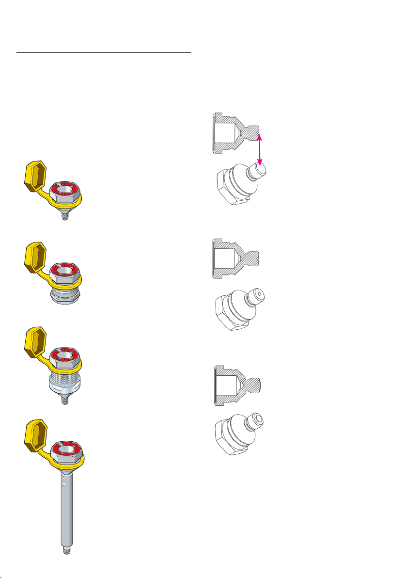
The VIBCODE sensor is operated together with
a compatible, portable measuring device. For
measurement, the VIBCODE sensor is connected
to a coded VIBCODE stud, which is permanently
installed on the machine.
VIBCODE sensors of series VIB 8.660 HEX are per-
mitted for use in the Ex-zone in accordance with
ATEX guidelines.
Safety instructions
•Read these operating instructions carefully and
keep them in a safe place.
•Observe the operating instructions of the devic-
es to be connected.
•Only use the sensors as intended and only for
the permitted purpose of application.
• Only use original accessories.
• Replace defective sensors and cables.
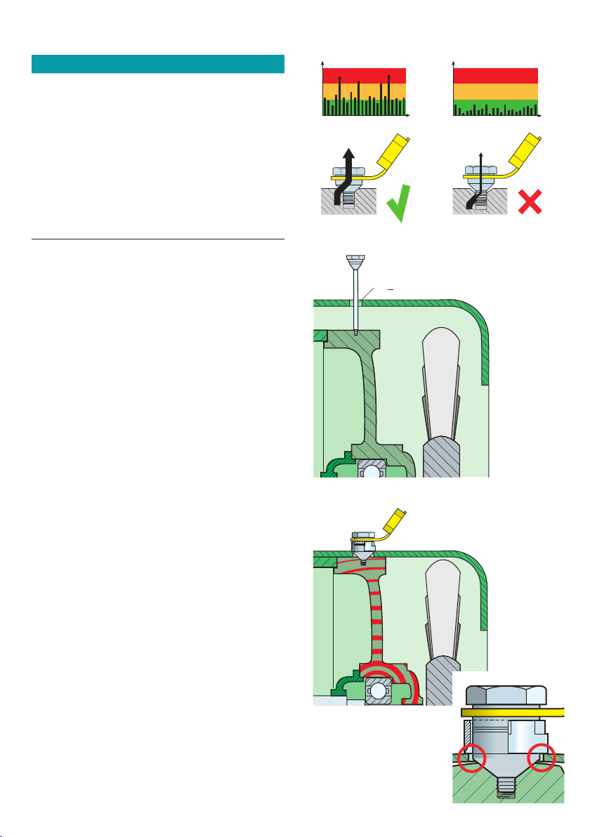
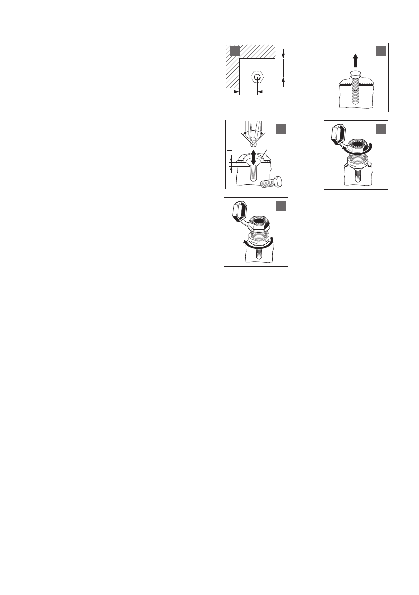
•Have installation of the VIBCODE studs carried
out by qualified personnel exclusively.
•Comply with the applicable safety regulations
when performing installation tasks on the ma-
chine in operation.
•Observe the technical specifications and permis-
sible operating conditions. If in doubt, contact
PRUFTECHNIK.
•VIBCODE sensors are compliant with the appli-
cable European directives. The complete Decla-
ration of Conformity is available under www.
pruftechnik.com/certificates.
Safety instructions for installation and operation
in the Ex-zone:
•Only VIBCODE sensors of series VIB 8.660 HEX
are permitted to be operated in the Ex-zone.
•Sensors of series VIB 8.660 HEX are only to be
connected to certified intrinsically safe circuits
giving due consideration to the following max-
imum values:
Ui= 30 V; Ii= 63 mA; Pi = 300 mW;
Ci = 347 nF; Li= negligibly small.
•The following devices may also be connected
to the VIBCODE VIB 8.660 HEX with their
intrinsically safe analogue output circuits. The
connection must take place via a cable with a
maximum length of 10 m an inductance per
unit length of L’ <1µH/m and a capacitance per
unit length of C’ < 120 pF/m.
– VIBSCANNER type VIB 5.400 EX / EC-Type Ex-
amination Certificate No. TÜV 01 ATEX 1699
– VIBXPERT type VIB 5.300 EX - xx / EC-Type Ex-
amination Cert. No. ZELM 07 ATEX 0355 X
•The permissible ambient temperature range is
between -20°C and +80°C [-4°F ... + 176°F].
•
•
The European installation regulations are to be
observed (EN 60079-14).
The information in the type-examination cer-
tificate is to be observed: TÜV 02 ATEX 1890,
incl. 1st supplement, issued october 6th, 2008.
Available on www.pruftechnik.com.
• Labeling of the sensors:
II 2G Ex ib IIC T4
Compatibility
• VIBCODE - VIB 8.660 HEX, S.N. > 00101
Device:
– VIBSCANNER EX, firmware > 1.66
– VIBXPERT EX, all versions
• VIBCODE - VIB 8.660, S.N. > 2362
Device:
– VIBSCANNER, firmware > 1.66
– VIBXPERT, all versions
Maintenance and repair work
Operation of the sensors does not require any
maintenance. Repair work by the user is not
possible.
Storage
•Store the VIBCODE sensor in the case of the
device.
• Conditions at the storage location:
– Dry and free of dust
– Temperatures are within the permissible range
– Vibration-free
– No high electromagnetic fields
– No corrosive materials
Disposal
After use, dispose of the sensor in an environ-
mentally friendly manner and in accordance with
national provisions.
S.N.

3
Function
VIBCODE is a vibration sensor system that uses
coded measurement studs for certain identifica-
tion of measurement locations on the machine.
The system consists of the VIBCODE sensor and
the VIBCODE measurement stud.
VIBCODE sensor
The VIBCODE sensor contains a code ring sensor
and a vibration sensor. The sensors locks onto the
VIBCODE stud via bayonet mount in optimum po-
sition and with consistent pressure. Trend readings
are taken with perfect repeatability regardless of
operator qualification and training. The code ring
sensor reads the tooth pattern of the plastic ring
in the measurement stud to determine its location
so that the correct types of measurement can be
taken. Mixups, erroneous trend deviations and
time-consuming repeat measurements are all
eliminated once and for all.
Code ring sensor
Vibration sensor
VIBCODE
®®
VIBCODE

4
M8 – VA1.4571
VIBCODE stud,
for threaded mounting
for adhesive mounting
... with locking nut
... with extension post
VIBCODE stud
A VIBCODE stud consists of a stainless steel bolt, a
protective cap and a coded plastic ring. Coding is
achieved by cutting out individual teeth.
VIBCODE studs are available in various types as
an accessory.
UNC5/16 – VA1.4305
Distinctive feature
VIBCODE studs with screw thread are available
in two thread sizes and stainless steel qualities.
For better differentiation, the threaded bolts are
marked accordingly:
M8 – VA1.4305

5
Technical data
PARAMETER VIBCODE sensor
Measurement
Signalling system Current Line Drive (CLD)
Transmission factor
(Ref.: 159 Hz; 25 °C [77°F]) 1.0 µA/ms-2 ± 4%
Frequency range ± 3dB 1.5Hz ... 20kHz
Measurement range r.m.s. 961 ms-2 [ 98 g ]
Resonance frequency 36kHz
Linearity range ± 10% ± 50 ms-2 [ ± 5 g ]
Electrical
Power supply > 10 mA / 7-18 VDC
Noise, rms < 1mms-2 / Hz-1/2 at 10 Hz
Output impedance > 500 kOhm
Environment
Degree of protection IP 65, w/ cable connected
Transverse sensitivity < 10 % of axial value
Temperature sensitivity < 0.3ms-2/K
Magnetic sensitivity < 14ms-2/T bei 50 Hz
Temperature range,
VIB 8.660 - 10 °C ... + 70 °C [ 14°F ... +158°F ]
Temperature range,
VIB 8.660 HEX - 20 °C ... + 80 °C [ -4°F ... +176°F ]
Mechanical
Mounting bayonet mount
Weight 390 g
Cable connector TNC
PARAMETER VIBCODE stud
Bolt
Mounting Screw thread, adhesive, locking nut,
extension post
Material Stainless steel (VA1.4305 /
VA1.4571)
Code ring
Material Hostaform®
Resistance Oil, coolant
Temperature range -40°C ... +130°C [ -40°F ... +270°F ]
Protective cap
Material Desmopan®
Resistance Oil, coolant
Temperature range -30°C ... +100°C [ -22°F ... +212°F ]
136 mm
5 3/8"
VIBCODE
®
1 5/8"
39 mm
Dimensions

6
Installation
The frequency behavior and dynamic range of
the VIBCODE sensor can be heavily influenced by
installation of the VIBCODE stud. Poor coupling
with the measurement location dampens the
signal and restricts the frequency range. As a gen-
eral rule, the sensor requires firm, friction-locked,
contact and resonance-free attachment to the
measurement location. This particularly applies to
measurements at high frequencies.
Basically, the following applies:
10 x Weight Sensor < Weight object to be measured
The most stable coupling to the measurement
location can be achieved by screw mounting. If
screw mounting is not possible, the VIBCODE stud
can be glued to the measurement location.
Screw mounting
Applies to VIBCODE threaded studs M8 / UNC
5/16.
Required tools and resources
– Hand-held drill
– Drill bits (3.5mm /6.8 mm) with depth gage ring
– 90° countersink bit (VIB 8.694)
– Thread tap M8 or UNC 5/16-18
– Torque wrench with 19 mm / 3/4“ hex socket
– Compressed air for cleaning out the hole
– Solvent for degreasing
– Threadlocker (LOCTITE 243)
Select the point of installation
• The drilled hole must have direct connection to
the bearing carrier if the sensor should measure
shock pulse signals.
• Minimum distance between the drilled hole
and protruding edges of the housing must be
35 mm (A). Allow adequate clearance to attach
the wrench.
Note
Ensure that a hole can be drilled at the chosen
location.
Drill threaded hole
• Drill pilot hole: 3.5 mm / 15 mm deep (B).
• Bore out hole: 6.8 mm / 15 mm deep (C).
• Contersink hole: 90° / 3 mm deep (D).
• Blow out the hole.
• Grease thread tap.
• Tap thread: 12 mm deep (E).
• Blow out the hole.
Mount stud
• Clean the contact surfaces of the stud and the
machine with solvent.
• Allow contact surfaces to dry.
• Thinly apply LOCTITE 243 to improve signal
transmission.
• Affix the protective cap to the stud and, if avail-
able, insert the code ring into the stud.
• Screw in the stud and tighten with a torque
wrench (11 Nm, F).
• Check the stud for tight mechanical fit.
> 35
Abmessungen in mm
3,5
>15
>12
UNC
5/16
6,8 90°
>3
11 Nm
A B
C D
E F
M8

7
Notes
Excessive torque can damage the thread or the
machine housing. Too little torque can allow the
stud to work loose. Incorrect torque always causes
measurement errors!
The tapered shank section must seat perfectly into
the countersunk hole so that proper signal trans-
fer from the machine to the sensor (left) can take
place over a large area of the shank.
If there is only partial contact, then transmission
will be poor (right).
Extension bar
The VIBCODE stud with extension bar is ideal for
situations such as motor housings where there is
much clearance between the actual mounting lo-
cation (e.g. the bearing housing) and the housing
cowling. This stud is available in various lengths
with an M8 or UNC 5/16 thread at its bottom.
To ensure optimal signal transmission, the hous-
ing cowling and extension bar may not come
into contact. Therefore, the feed-through for the
extension bar must have a diameter of at least
15 mm.
The longest extension (170mm and 6 5/8”) may
be used only for taking shock pulse readings and
not for vibration measurement!
Locking nut
The VIBCODE stud with locking nut is suitable for
measurement locations which are covered by a
housing cowling and can be reached without ex-
tension. The stud can also replace existing housing
screws.
To ensure optimum signal transmission, the bolt
must not touch the housing cowling. The bore
must therefore be drilled in such a way that the
bolt has a sufficient distance to the housing cowl-
ing and at the same time the housing cowling can
be tightened with the locking nut.
Bolt and housing cowling
must not touch each other
Ø > 15 mm

8
Replacing the housing screw
Required tools and resources
– Hand-held drill
– Drill bit (> 19 mm)
– 90° countersink bit (VIB 8.694)
– Thread tap M8 or UNC 5/16-18
– Torque wrench with 19 mm / 3/4“ hex socket
– Compressed air for cleaning out the hole
– Solvent for degreasing
– Threadlocker (LOCTITE 243)
Select the point of installation
•The drilled hole must have direct connection to
the bearing carrier if the sensor should measure
shock pulse signals.
•Minimum distance between the drilled hole and
protruding edges of the housing must be 35
mm (A’). Allow adequate clearance to attach
the wrench.
Prepare mounting bore
• Remove housing cowling (B‘).
• Contersink hole: 90° / 3 mm deep (C‘).
• Blow out the hole.
•Bore out housing cowling, d > 19 mm (C‘). VIB-
CODE bolt and cowling must not be in contact
after mounting. The cowling is held in place by
the locking nut only!
Mount stud
•Clean the contact surfaces of the stud and the
machine with solvent.
• Allow contact surfaces to dry.
•Thinly apply LOCTITE 243 to improve signal
transmission.
•Affix the protective cap to the stud and, if avail-
able, insert the code ring into the stud.
• Reinstall the cowling.
•At the appropriate location, the VIBCODE stud
is connected to the cowling as follows:
•Screw in the stud and tighten with a torque
wrench (11 Nm, D’).
•Then tighten the locking nut against the cowl-
ing (E‘).
• Check the stud for tight mechanical fit.
> 35
Dimensions in mm
90°
>3
11 Nm
A‘ B‘
C‘ D‘
E‘
d > 19

9
Adhesive mounting
Applies to VIBCODE studs with bonding base.
Required tools and resources
– Hand-held drill and drill bit (3.5 mm)
– Angle grinder and rasp
– Compressed air for cleaning out the hole.
– Solvent for degreasing
– 2-Component adhesive (WEICON HB 300,..)
Note
Switch off the machine and secure it against a
restart. Do not switch on the machine until the
adhesive has hardened (approx. 24 hours).
Select the point of installation
•The point of installation must have direct
connection to the bearing carrier if the sensor
should measure shock pulse signals.
•Allow sufficient space for applying the adhesive
with a wooden spatula.
Prepare bonding location
•Grind down existing coats to the bare metal (Ø
> 30 mm, G).
• If necessary, grind down the location (G).
•Sand down the point of installation with a rasp
and file several grooves in a diamond pattern
for greater adhesive strength (G).
Optionally, and only if drilling is possible:
•Drill hole for centering pin: 3.5 mm / 5 mm deep
(H). Remove the centering pin from the stud if
drilling is not possible.
• Blow out the hole.
•Clean the contact surfaces of the stud and the
machine with solvent.
• Allow contact surfaces to dry.
Apply adhesive
• Prepare the adhesive for use.
•Apply the adhesive with a wooden spatula
evenly to the base of the stud and the bonding
location (approx. 1 mm thick, I).
Affix VIBCODE stud
•Affix the protective cap to the stud and, if avail-
able, insert the code ring into the stud.
•Press the stud gently against the bonding loca-
tion and turn it to evenly distribute the adhe-
sive. If applicable, screw in the centering pin (J).
•Do not remove excess adhesive. If necessary,
apply additional adhesive around the bonding
location for greater stability.
•If necessary, use adhesive tape to hold the stud
in place during hardening (K).
K
30
3.5
5
Dimensions in mm
GH
I J

10
Performing measurement
After VIBCODE is inserted in the coded measure-
ment stud, the measuring device recognizes the
measurement location and automatically calls up
the measurement tasks for this location. Measure-
ment either begins automatically or must be start-
ed by pressing a button on the measuring device.
Additional details can be found in the measuring
device documentation.
Attach the VIBCODE sensor
• Open the protective cap of the VIBCODE stud.
•If necessary, remove the protective cap from the
VIBCODE sensor.
•Place the VIBCODE sensor on the VIBCODE
stud.
•Press the VIBCODE sensor lightly and tighten
it clockwise until stop. The sensor is locked by
means of a bayonet connection.
•Check whether the sensor is fixed correctly in
the stud.
•To unplug, turn the sensor counterclockwise
until the lock is released. Do not pull the cable.
Notes
Never use the VIBCODE sensor to take a mea-
surement directly from the machine surface. This
sensor must always be locked onto the VIBCODE
stud!
Do not remove the VIBCODE sensor from the VIB-
CODE stud during measurement.
Do not unplug the VIBCODE sensor from the mea-
suring device when the code ring is being read.
Only leave the VIBCODE sensor attached to the
VIBCODE stud for as long as necessary as, other-
wise, the spring tension of the sensor will be too
heavily stressed.
Before mounting the VIBCODE sensor on the
stud, measure the temperature of the stud with
a temperature probe. VIBCODE studs may not
exceed a maximum temperature of 70°C / 158°F
during measurement. If the measurement takes
no longer than five minutes, the temperature may
reach a maximum of 80°C / 176°F.
¨�
¨�

11
Cleaning
•Slight soiling on the sensor can be washed off
using soap solution or isopropyl and a cotton
cloth.
•To prevent damage to the delicate components
in the head of the sensor, use a paintbrush for
cleaning them.
•If you use compressed air for cleaning, only use
a weak jet of air.
Notes
Never use solvent for cleaning!
Do not scratch off any soiling using screwdriver
blades or other hard objects !
To prevent damage to the VIBCODE sensor and
avoid soiling, please observe the following in-
structions:
•Do not apply lubricating oil or grease to the
VIBCODE stud or sensor.
•After the measurement, always replace the
protective caps.
VIBCODE
¨
Encoding
The stud contains a plastic code
ring that obtains an unique identity
- similar to a fingerprint - through
the removal of individual teeth. The 4-digit coded
patterns are defined with the aid of the PC soft-
ware (OMNITREND / OMNITREND Center) and
are cut out with the VIBCODE ring encoding tool
(VIB8.692).
Cut out code pattern
•Insert the code ring into the appropriate slot of
the encoding tool (1).
• Insert the plunger (2).
• Set the first code number (3).
• Slowly press down the plunger (4).
•Repeat the procedure for the next code num-
bers accordingly.

Fluke Deutschland GmbH
85737 Ismaning, Germany
www.pruftechnik.com
Productive Maintenance Technology
VIB 9.834.G
08.2018
https://pruftechnik.com/com/About-us/
Company/Certificates-and-Material-Safety/
This manual suits for next models
1
Table of contents
Other Fluke Accessories manuals

Fluke
Fluke 700P00 Service manual

Fluke
Fluke Thermalert 4.0 User manual

Fluke
Fluke 9135 User manual

Fluke
Fluke 750P User manual

Fluke
Fluke 80T-150UA User manual

Fluke
Fluke 3562 User manual

Fluke
Fluke PPC4 User manual

Fluke
Fluke 80K-15 User manual

Fluke
Fluke 700P29 User manual

Fluke
Fluke FLK-075-CLV Instruction manual

Fluke
Fluke VIB 6.631 Owner's manual

Fluke
Fluke 80PK-IR User manual

Fluke
Fluke 9040 User manual

Fluke
Fluke 3563 User manual

Fluke
Fluke RUBBER SHOE ACCESSORY PN 3125710 User manual

Fluke
Fluke 805ES User manual

Fluke
Fluke 80PK-3A User manual

Fluke
Fluke Thermalert 4.0 Series User manual

Fluke
Fluke 80i-110s User manual

Fluke
Fluke U1500s User manual